Steel Structure Warehouse Solutions for Storage, Logistics & Industry
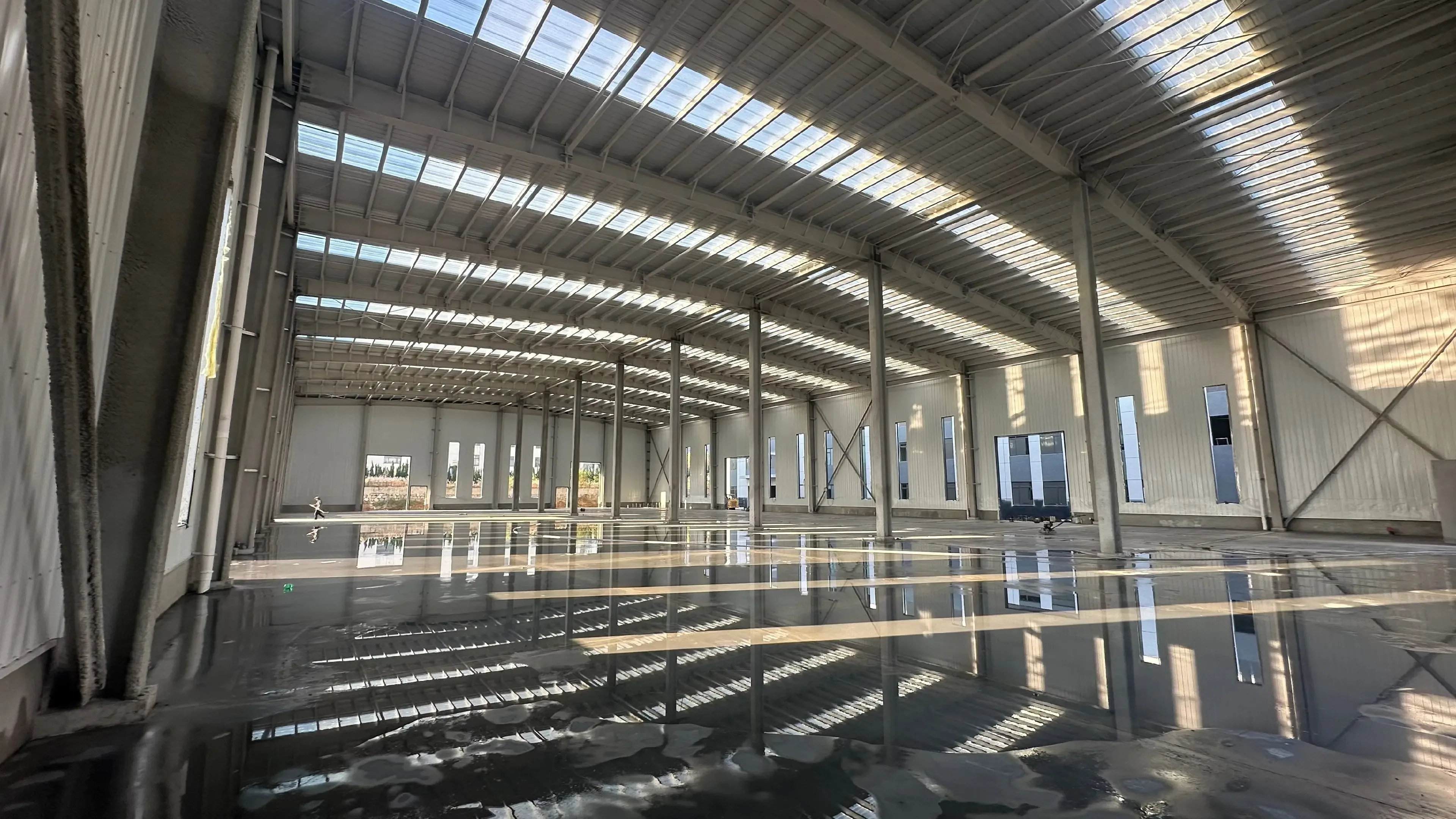
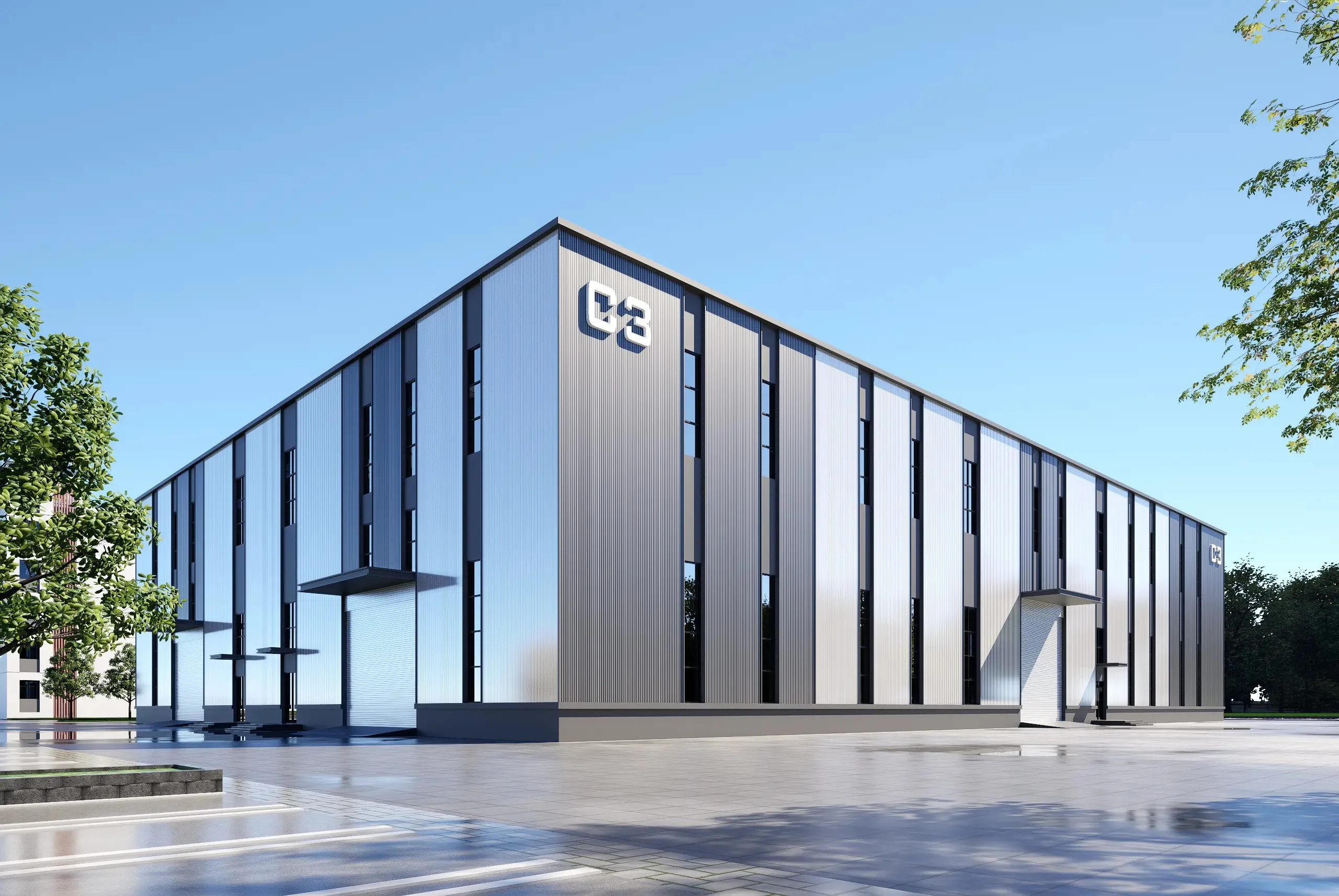
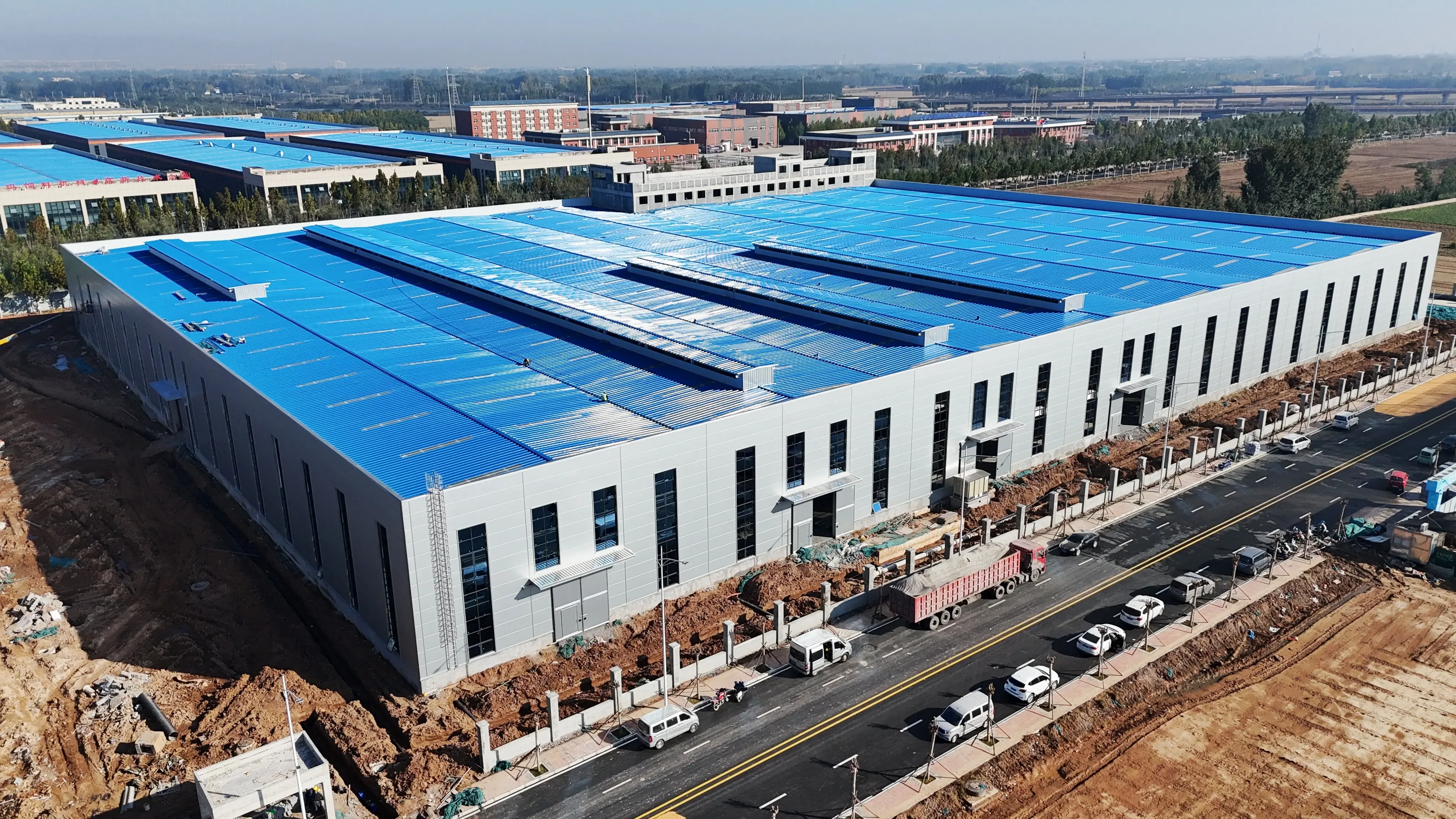
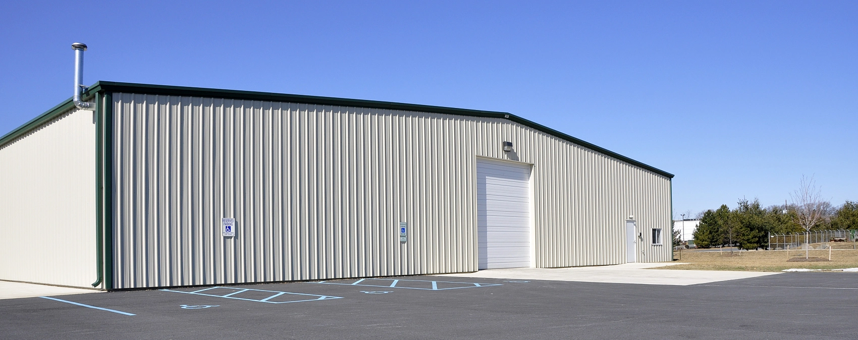
A prefabricated steel warehouse is a customizable building system designed around the way a business stores goods, handles materials and operates day to day. The main frame, secondary members, roof and wall cladding, doors, insulation and ventilation are coordinated to suit the required clear space, site conditions and local design requirements. Components are fabricated in the factory and assembled on site, helping make project scope, quality checks and installation planning easier to coordinate.
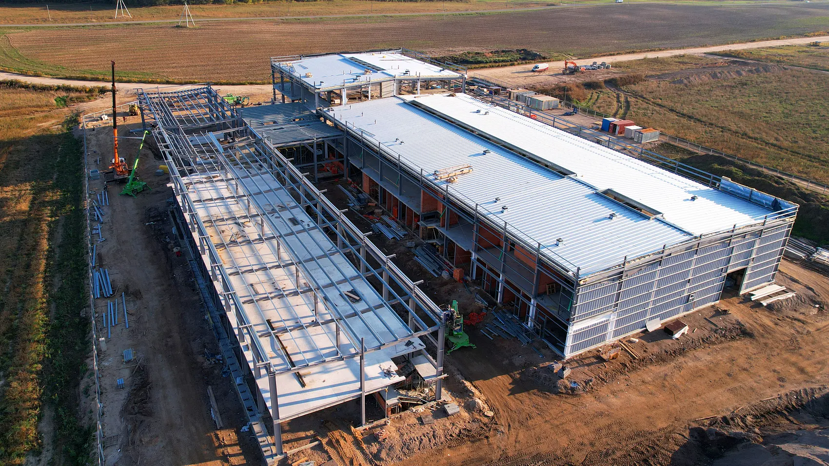
Warehouse layouts generally include clear-span portal frames, multi-span buildings with interior columns, and truss-based structures for wider spaces or specific equipment requirements. The right option depends on the required unobstructed working area, building dimensions, wind and other site loads, handling equipment, insulation needs and budget. Factory-fabricated components can also help coordinate construction activities and reduce the amount of work required on site compared with fully site-built construction.
Structural System Taxonomy
The complete industrial warehouse envelope provides a continuous load path divided into four primary subsystems:
- Primary Framing: Continuous rigid frames composed of built-up welded H-section rafters and columns. Webs and flanges are cut via CNC automated plasma systems to ±0.5 mm tolerances and welded via automated submerged arc welding (SAW) per AWS D1.1. Structural depth tapers along the frame to match the internal bending moment diagram, eliminating unneeded dead weight at inflection points.
- Secondary Framing: Cold-formed Z-shaped roof purlins and C-shaped wall girts conforming to ASTM A653 with a minimum Z275 (275 g/m²) galvanized zinc coating. Beyond directly supporting cladding assemblies, secondary members provide lateral torsional restraint to the compression flanges of primary rafter members.
- Bracing Subsystems: Horizontal roof bracing and vertical sidewall cross-bracing utilizing tension rods or structural angle assemblies (ASTM A36). These elements transfer longitudinal wind loads, crane thrust forces, and seismic acceleration down to the anchor bolts, holding an installation layout tolerance of ±3 mm, subject to the approved project tolerances.
- Envelope Systems: High-tensile standing-seam metal roof systems and polyurethane (PIR) core insulated sandwich wall panels, sealing the building envelope against atmospheric corrosion and moisture intrusion.
Surface preparation in our Taian fabrication shop adheres strictly to ISO 8501-1 Sa 2.5 shot-blasting criteria, receiving an initial shop-applied coat of two-component epoxy zinc-rich primer at 80 μm Dry Film Thickness (DFT) to ensure structural longevity in corrosive industrial environments.
| Structural Parameter | Light Pre-Engineered Portal Frame (PEB) | Conventional Structural Mill Framing | Heavy Industrial Process Framing |
|---|---|---|---|
| Primary Standards | MBMA, AWS D1.1 and applicable local code | Applicable structural code and ASTM A992 | Applicable structural code and AWS D1.1 |
| Clear Span Range | 18 m to 48 m column-free | 15 m to 30 m | 12 m to 24 m (heavy bay loading) |
| Structural Steel Density | 22 to 38 kg/m² | 45 to 65 kg/m² | 75 to 130 kg/m² |
| Primary Member Profile | Variable-depth built-up welded plates | Hot-rolled wide-flange (W-shapes) | Heavy built-up box sections and H-beams |
| Secondary Framing Type | Cold-formed Z and C sections (2.0 to 3.0 mm) | Hot-rolled channels and angles | Heavy cold-formed or rolled channels |
| Anchor Bolt Tolerance | ±3 mm layout field tolerance | ±3 mm layout field tolerance | ±1.5 mm precise sleeve installations |
| On-site Erection Velocity | 1,500 to 2,500 m² per week | 800 to 1,200 m² per week | 400 to 700 m² per week |
Warehouse Structure, Components & Building Envelope
A steel warehouse is supplied as a coordinated building package rather than a collection of unrelated parts. The primary frame, purlins and girts, bracing, roof and wall cladding, flashings, fasteners and selected accessories work together to create the required usable space and weather protection. The final package is defined around the project dimensions, operating environment and the buyer's agreed supply scope.
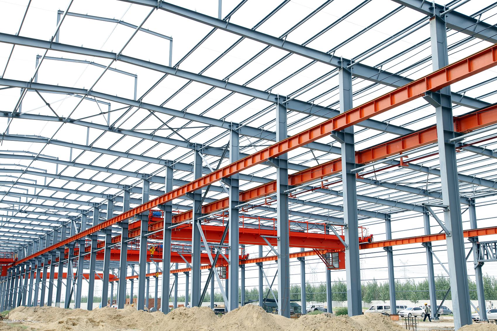
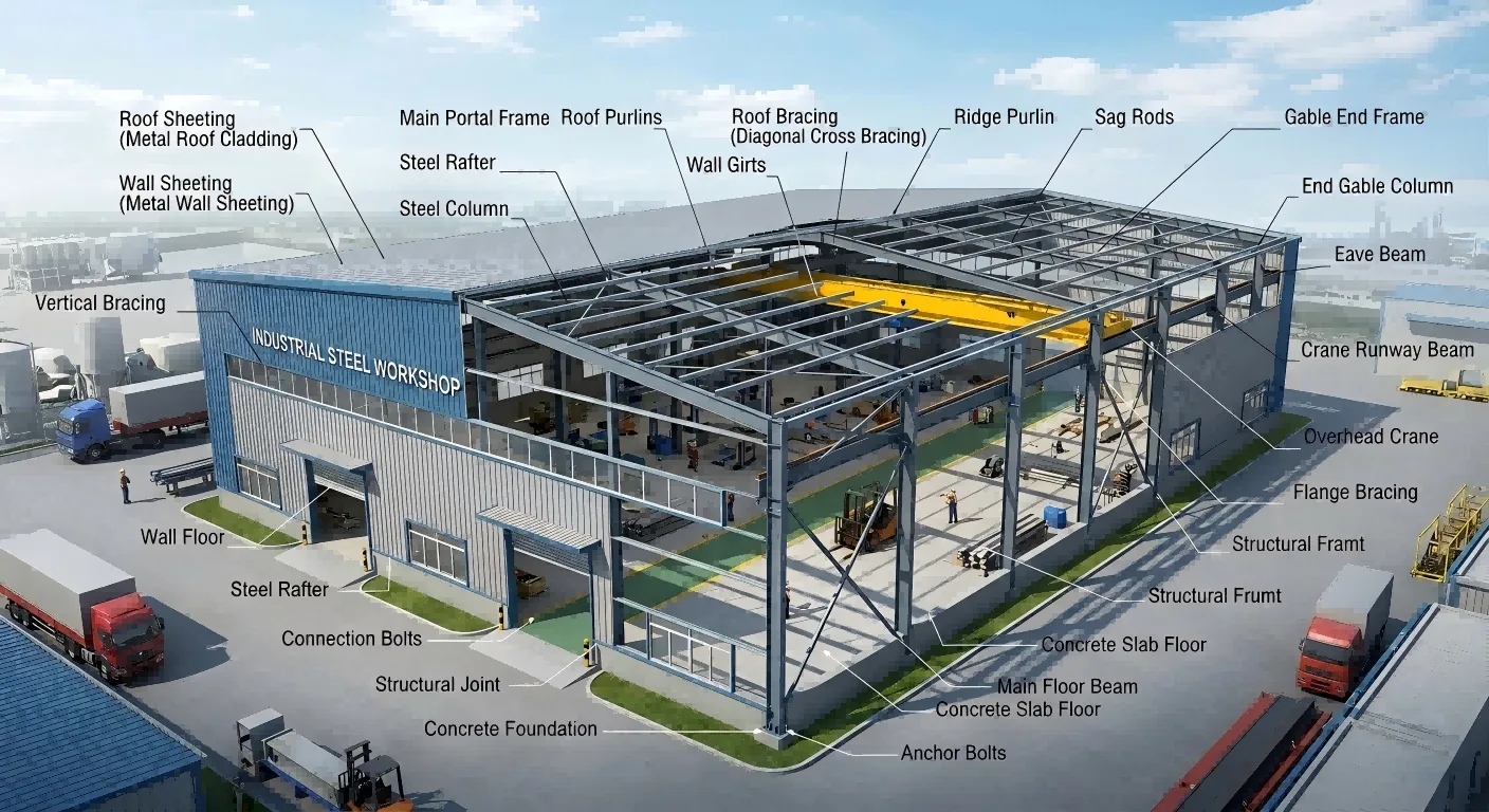
Understanding this system requires deconstructing the warehouse anatomy into three interdependent assemblies, detailing how structural loads transfer safely from exterior envelope surfaces down to the reinforced concrete foundations.
1. Primary Structural Framing Assembly
The primary structural skeleton carries tributary gravity loads and lateral wind or seismic forces. It consists of factory-built moment-resisting portal frames, wind columns, and runway crane girders.
- Tapered and Prismatic Welded H-Sections: Fabricated from ASTM A992 or GB/T 1591 Q355B plate steel. Web and flange plates are cut using automated multi-torch CNC plasma cutting systems holding strict cutting tolerances of ±0.5 mm. Plate components are fitted and welded using automatic submerged arc welding (SAW) per AWS D1.1 standards. Tapered profiles optimize structural self-weight by deepening the section at locations of maximum bending moment (the knee joints) and reducing depth toward hinge points and the apex.
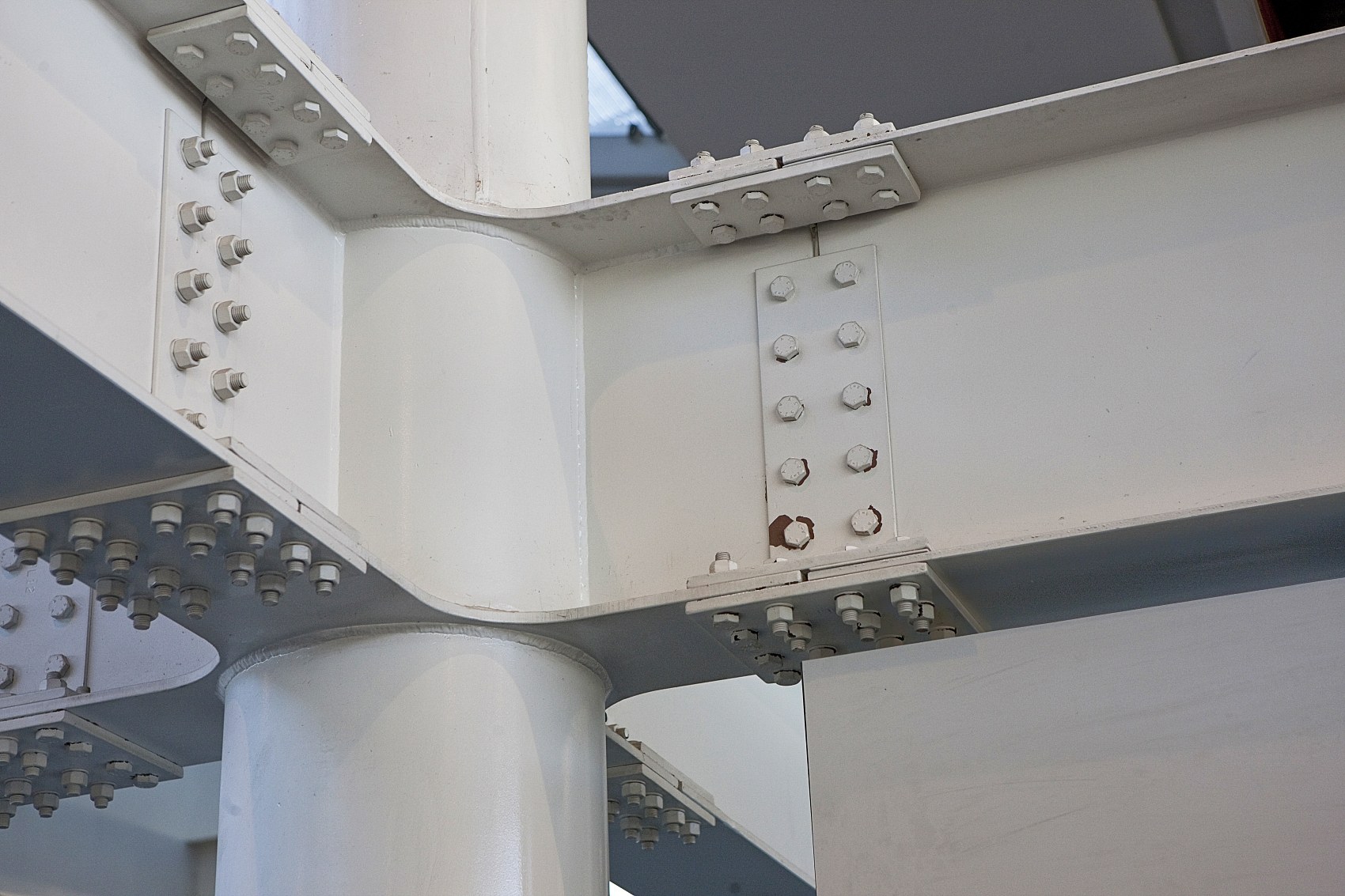
- Rigid Moment-Resisting Knee and Apex Joints: Flange and web connection plates are shop-welded with complete-joint-penetration (CJP) groove welds. In the field, rafter-to-column connections rely on high-strength ASTM A325 or ASTM A490 structural bolts (or ISO 898-1 Grade 10.9 equivalents). These are torqued in calibrated pre-tensioned or slip-critical configurations in accordance with the approved connection design requirements to resist cyclic wind-induced dynamic moments.
- Crane Runway Brackets (Corbels): Welded directly to the inner column flange, these brackets transmit dynamic vertical wheel loads and lateral bumper forces from overhead bridge cranes down the column shaft. Fatigue life and bracket deflection are checked against the applicable crane design requirements.
- Gable Wind Columns (Endwall Posts): Vertical prismatic H-sections positioned at building endwalls to resist wind pressure and wind suction acting on the gable walls. They deliver wind shear to the roof horizontal bracing truss and the ground foundation.
2. Secondary Structural Framing Assembly
Secondary structural members stabilize the primary frames, bridge the open bays, and directly support the roof and wall cladding.
- Cold-Formed Z-Purlins and C-Girts: Profiled from structural galvanized steel coil conforming to ASTM A653 CS Type B or Grade 50 (with Z275 / G90 zinc coating). Secondary cold-formed Z-purlins achieve structural continuity through overlapping lap joints over rafters, increasing load capacity by up to 25%. Nested overlapping lengths are engineered to span across negative moment zones over the portal rafters, maximizing both cross-sectional capacity and rotational stiffness.
- Eave Struts: Heavy cold-formed or hot-rolled boundary members positioned along the eaves line. They serve a dual structural role: supporting the low edge of the roof sheeting and the upper edge of the wall sheeting while acting as horizontal chord elements in longitudinal perimeter bracing struts.
- Sag Rods and Anti-Sag Angles: Threaded round solid steel bars (typically 12 mm to 16 mm diameter) installed normal to the purlin and girt webs. These tension components maintain purlin alignment, prevent mid-span lateral sagging under dead loads, and stabilize cold-formed profiles against web crippling.
- Diagonal Flange Braces and LTB Restraint: Connected directly between the secondary purlin/girt system and the inner compression flange of the primary column or rafter. As part of the structural stability checks, an unbraced compression flange will fail prematurely via lateral-torsional buckling (LTB) before the cross-section reaches its full plastic bending capacity (Mp). Flange braces directly restrain the rafter bottom flange under wind uplift reversal conditions. When extreme wind suction causes net upward pressure on the roof, the bottom flange shifts from tension into severe compression; diagonal flange braces (typically 45-degree angle steel) transfer these stabilizing bracing forces directly back into the diaphragm-anchored roof purlins.
3. Building Envelope Subsystems
The envelope system weatherproofs and insulates the structural core while contributing shear diaphragm action when engineered into the structural analysis.
- Insulated Sandwich Panels (PIR/PUR and Rockwool): Factory-formed composite panels featuring twin prepainted galvanized steel facings (typically 0.5 mm to 0.7 mm thick) bonded to a core material. PIR/PUR core sandwich panels achieve thermal conductivity as low as 0.022 W/(m·K) and Class B-s1,d0 reaction to fire. For processing plants or logistics hubs demanding strict fire compartmentation, structural Rockwool cores (density 100 kg/m³ to 120 kg/m³) deliver non-combustible Class A1 performance and 1 to 4 hour fire ratings per ASTM E119 and EN 1365-2.
- Profiled Single-Skin Sheeting: Roll-formed trapezoidal steel sheets coated with high-durability fluorocarbon (PVDF) or silicone-modified polyester (SMP) paint systems, paired with interior vapor barriers and glass fiber insulation batts for unconditioned dry storage applications.
- Continuous Skylights and Flashing: Impact-resistant, UV-stabilized polycarbonate or glass-fiber reinforced polyester (GRP) profiled roof lights integrated into the cladding profile. Prefabricated base flashings, ridge caps, and drip trims (minimum 0.6 mm galvanized pre-painted coil) seal envelope openings using butyl mastic and EPDM-gasketed fasteners to prevent water intrusion.
Engineering Load Path Architecture
A primary duty of industrial warehouse design is tracing environmental and operational forces through structural load paths without excessive deflection or stress concentrations:
- Lateral Wind Pressure / Roof Snow Loads: Surface pressure hits the envelope cladding, transferring normal forces through self-drilling carbon steel fasteners into the cold-formed Z-purlins or wall C-girts via bending.
- Secondary-to-Primary Frame Transfer: Purlins and girts deliver point-load reactions into primary rafter and column outer flanges. Flange braces and bracing struts simultaneously secure rafter compression flanges against LTB.
- Portal Frame Dissipation: Primary portal rafters resolve forces into high internal shear forces and bending moments, shunting lateral base shear and axial gravity loads down through the rigid moment-resisting knee joints into the tapered vertical columns.
- Foundation Anchorage Transfer: Columns land on base plates fabricated from ASTM A36 / Q235B steel (typically 25 mm to 60 mm thick). Factory tolerances demand anchor bolt cage field layouts within ±3 mm accuracy. High-strength cast-in-place anchor bolts (ASTM F1554 Grade 55 or Grade 105) transfer tensile uplift and overturning moments directly into reinforced concrete footings designed per ACI 318.
| Assembly Classification | Primary Structural Components | Standard Material Grade | Design Standard / Fabrication Tolerance | Surface Treatment & Prep |
|---|---|---|---|---|
| Primary Columns & Rafters | Built-up tapered and prismatic H-sections | ASTM A992 / Q355B | AWS D1.1 / Cutting ±0.5 mm / Camber span/1000 | Sa 2.5 Shot Blast, 80 μm DFT Epoxy Primer |
| Primary Knee & Apex Splices | Thick moment plates, stiffeners, A325/A490 bolts | ASTM A572 Gr 50 / Gr 10.9 | EN 1090-2 Execution Class 3 / project requirements | Hot-dip galvanized or shop-primed |
| Secondary Roof Purlins | Continuous cold-formed Z-profiles with lap splices | ASTM A653 HSLAS Gr 50 | AISI S100 / Deflection L/180 (snow), L/150 (uplift) | Hot-dip zinc coating Z275 (275 g/m²) |
| Secondary Wall Support | Cold-formed C-channels, eave struts, sag rods | ASTM A653 / Q235B round bar | AISI S100 / Web depth tolerance ±1.0 mm | Continuous hot-dip galvanized |
| Compression Bracing | Diagonal angle braces (equal leg angles) | ASTM A36 / Q235B | Structural stability checks / slenderness ratio KL/r < 200 | Electro-galvanized or painted |
| Envelope Roof Panels | Double-skin metal insulated PIR/PUR panels | 0.5 mm Galvalume + PIR core | EN 14509 / Thermal: 0.022 W/(m·K) / Class B-s1,d0 | Top coat PVDF 25 μm / Back coat 10 μm |
| Envelope Fire Barriers | Structural Rockwool sandwich panels | Prepainted sheet + 110 kg/m³ core | ASTM E119 / EN 13501-1 Class A1 non-combustible | Prepainted 25 μm polyester |
| Foundation Interface | Anchor bolts, shear keys, column base plates | ASTM F1554 Gr 55 / ASTM A36 | ACI 318 / Bolt cluster placement ±3 mm | Uncoated or hot-dip galvanized threads |
Choose the Right Steel Warehouse Layout
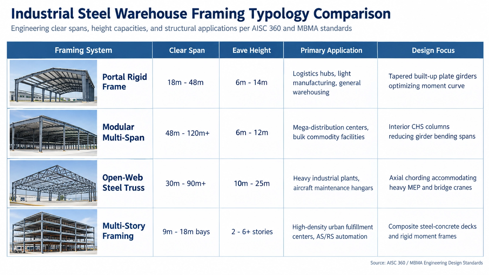
Selecting the structural layout affects usable floor space, column positions, steel quantity, foundations and installation planning. Clear-span portal frames suit many single-story storage and distribution buildings; multi-span layouts can be economical for wider footprints where interior columns are acceptable; and truss systems may suit larger spans or special equipment requirements. The choice should be made around the warehouse workflow and project-specific design conditions.
Typical Structural Framing Configurations
Clear-Span Portal Frame (18m - 48m)
Single-story column-free interior with solid-web tapered built-up H-sections. Optimum for bulk warehousing and standard AGV pathways.
Modular Multi-Span Frame (48m - 120m+)
Interior intermediate CHS or H-columns (18m-24m spacing). Reduces rafter depth by 35% and drastically optimizes foundation reaction forces.
Open-Web Truss System (30m - 90m+)
Pratt/Warren geometries resolving bending moments into pure axial forces. Supports 50-ton overhead cranes and integrates full MEP ducted corridors.
1. Clear-Span Portal Rigid Frames
Clear-span portal frames are the standard framing choice for single-story logistics facilities, manufacturing plants, and bulk distribution terminals requiring uninterrupted ground floor operations between 18 meters and 48 meters. The structure uses solid-web tapered built-up sections engineered from ASTM A572 Grade 50 or EN 10025-2 S355JR plate.
Portal frames with tapered built-up sections reduce steel consumption by 15-20% compared to uniform hot-rolled H-beams by matching cross-sectional modulus to the bending moment diagram. Plate cutting takes place on CNC plasma tables calibrated to tolerances within ±0.5 mm. Automated submerged arc welding (SAW) joins webs and flanges with full-penetration butt welds at the haunches and continuous fillet welds along the member lengths per AWS D1.1.
Haunch knees and apex connections require heavy end-plate moment connections with Grade 8.8 or 10.9 high-strength structural bolts pre-tensioned according to the approved connection design. Base plates transfer structural loads to reinforced concrete footings through anchor bolt clusters placed to ±3 mm tolerances to the approved project installation tolerances. All assemblies receive automated centrifugal shot blasting to Sa 2.5 profile depth (ISO 8501-1) followed by an 80-micrometer dry film thickness (DFT) zinc-rich epoxy primer coat.
2. Modular Multi-Span Frames
When logistical footprints expand beyond 48 meters up to 120 meters or wider, clear-span portal frames become uneconomical due to excessive rafter depths, transport limits, and oversized foundation reactions. Modular multi-span framing resolves this by introducing interior intermediate support lines spaced at 18-meter to 24-meter intervals.
Interior columns are structural Circular Hollow Sections (CHS) or hot-rolled ASTM A992 wide-flange shapes. CHS sections reduce collision profiles in forklift-heavy drive aisles while maintaining structural slenderness ratios using applicable member-stability criteria. Continuous multi-span rafter configurations allow engineers to reduce the primary girder depth by up to 35%, cutting down dead-weight loads on perimeter columns and isolated spread footings.
3. Open-Web Steel Truss and Space Frame Systems
For clear spans spanning 30 meters to past 90 meters, solid-web plate girders encounter flange buckling limits and prohibitive shipping weights. Open-web steel truss systems, configured in Pratt, Warren, or Howe geometries, resolve these mechanical limits by resolving bending moments into pure axial tension and compression forces within individual chords and web diagonals. Open-web trusses support clear spans exceeding 60 m while accommodating heavy ducted MEP and industrial overhead cranes up to 50 tons.
Warren Truss Crane Runway System
• Top Chord:
Axial compression handled by Square Hollow Sections (SHS).• Bottom Chord:
Axial tension carrying runway corbel connection.• Crane Runway Girder (CRG):
Built-up I-beam with cap channel reinforcement.• Rail Specification:
QU80 / QU100 rail locked with DIN 536 adjustable rail clips (up to 50 MT capacity).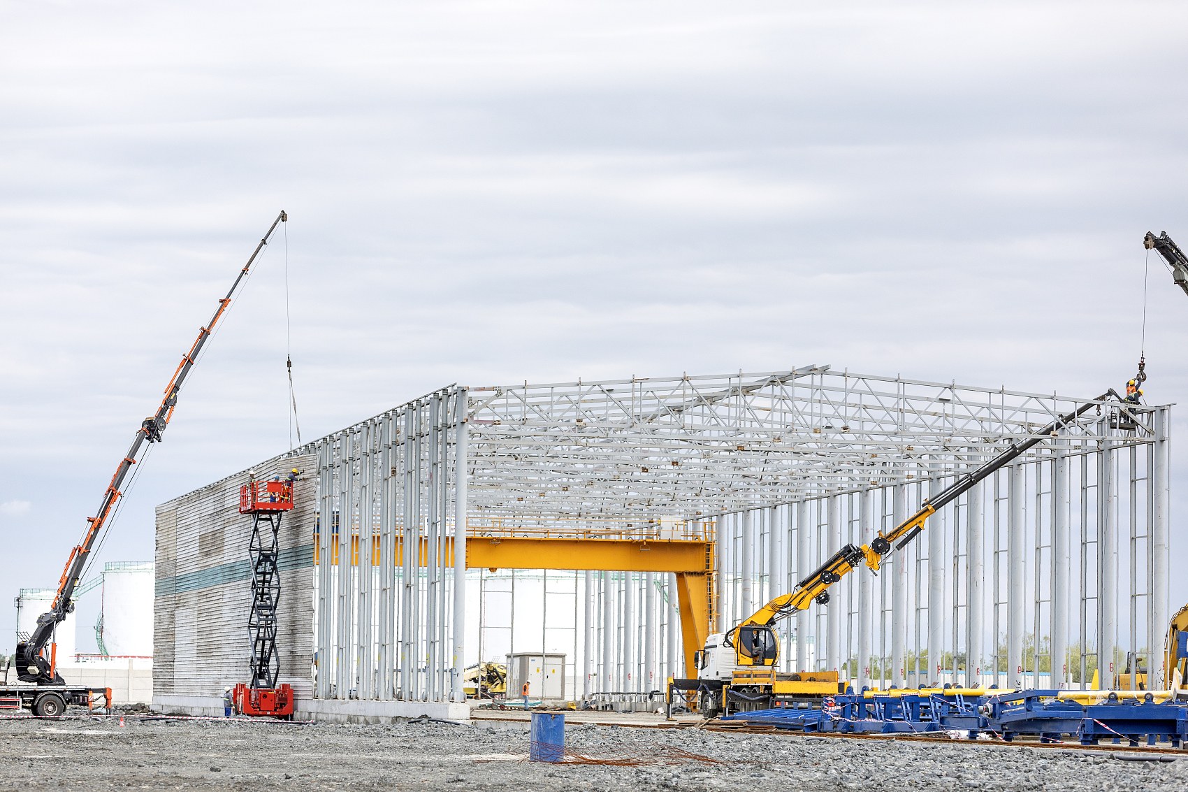
4. Multi-Story Structural Steel Framing
Constrained urban land footprints necessitate vertical expansion, driving the construction of multi-tier fulfillment centers and automated warehouses. These facilities integrate heavy hot-rolled structural steel moment-resisting frames (SMF) or braced frames (CBF/EBF) combined with composite floor deck diaphragms.
Flooring systems incorporate cold-formed profiled steel decking (typically 0.9 mm to 1.2 mm galvanized sheet) attached with welded headed shear studs per AWS D1.1 Section 7. These receive cast-in-place reinforced concrete topping slabs. Multi-tier automated logistics centers require composite floor slabs designed for floor flatness ratings of FF 50 / FL 50 to accommodate automated guided vehicles (AGVs). These stringent tolerances, validated via ASTM E1155, prevent vehicle sensor misalignment, dynamic tipping, and automated storage and retrieval system (AS/RS) mast deflection across elevated operations.
| Structural Typology | Standard Clear Span Range (m) | Structural Steel Consumption (kg/m²) | Primary Framing Design Standard | Primary Industrial Application |
|---|---|---|---|---|
| Clear-Span Portal Frame | 18 - 48 | 24 - 38 | Applicable local code / EN 1993-1-1 | Distribution centers, bulk storage, aircraft hangars |
| Modular Multi-Span Frame | 48 - 120+ | 18 - 28 | Applicable local code / EN 1993-1-1 | Mega-fulfillment centers, e-commerce sortation hubs |
| Open-Web Truss System | 30 - 90+ | 32 - 52 | Applicable local code / AWS D1.1 | Heavy manufacturing, 50-ton overhead crane facilities |
| Space Frame System | 40 - 100+ | 28 - 45 | EN 1993-1-1 / GB 50017 | Bulk dome terminals, large sports arenas, dry storage |
| Multi-Story Composite Frame | 9 - 18 (Grid) | 55 - 95 | Applicable seismic code / ACI 318-19 | Multi-level urban fulfillment centers, AS/RS towers |
Steel Materials, Finishes & Quality Standards
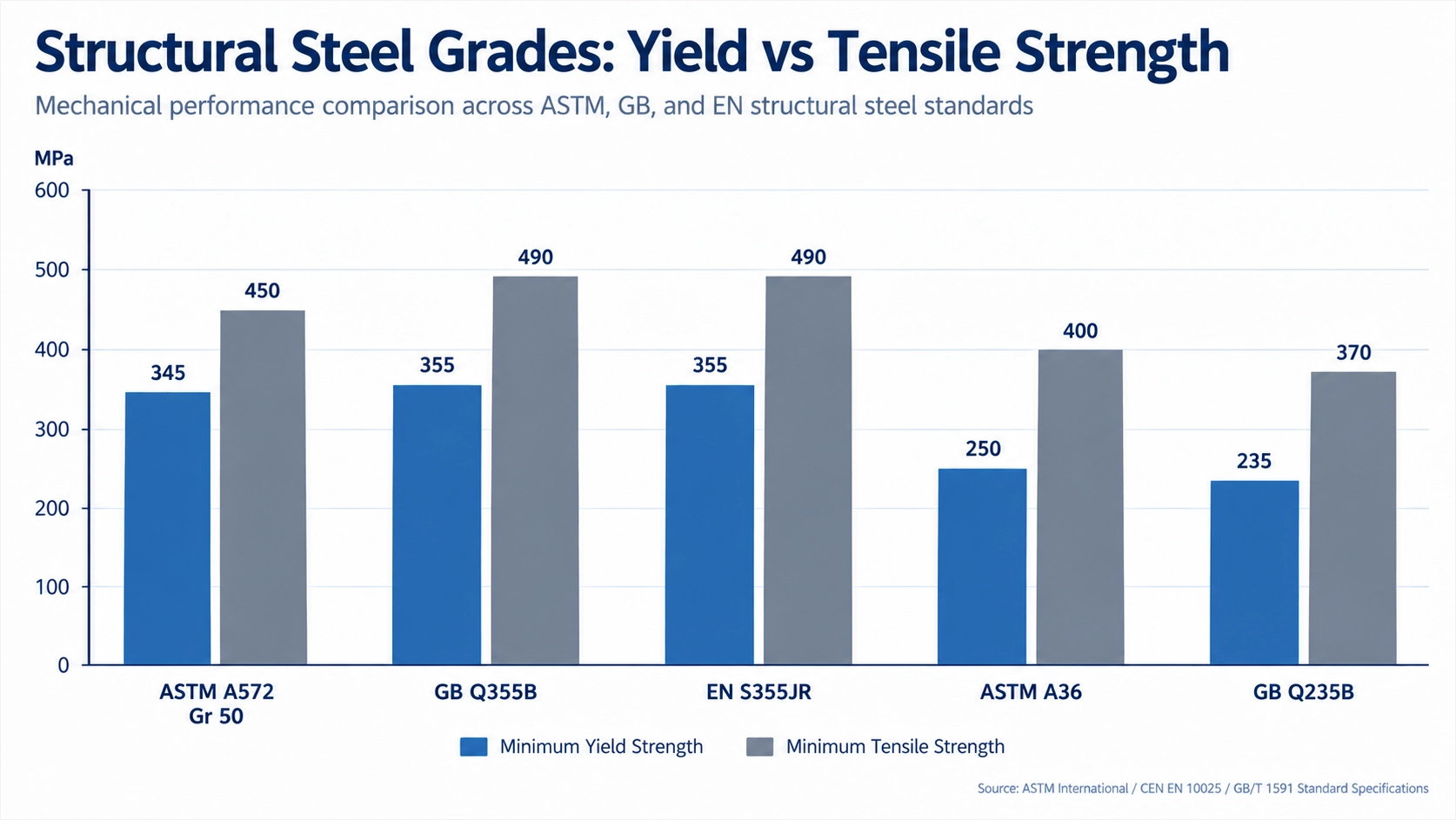
Metallurgical selection directly governs load capacity and fabrication economy in steel structure warehouse systems. When engineering global projects, procurement teams evaluate structural products across American (ASTM), Chinese (GB), and European (EN) specifications.
Primary Types of Structural Steel Products
Structural engineers classify industrial warehouse steel into four primary product forms based on manufacturing process and cross-sectional geometry:
- Hot-Rolled Wide-Flange Sections: Standardized W-shapes manufactured per ASTM A6 (or universal beams per EN 10034). These members are specified for primary building columns, multi-story mezzanine beams, and crane runway systems where uniform section properties are required.
- Built-Up Welded Plate Girders: Custom tapered or uniform I-sections fabricated by submerged arc welding (SAW) from cut structural plates per ASTM A572 Grade 50 or GB/T 1591 Q355B. These form primary portal frames, optimizing web depth and flange thickness along the bending moment diagram to maximize material efficiency over clear spans exceeding 48 meters.
- Hollow Structural Sections (HSS): Round and rectangular structural tubes manufactured to ASTM A500 Grade B/C or EN 10219. HSS members provide high torsional resistance and low drag coefficients, making them the standard choice for roof trusses and perimeter wind bracing.
- Cold-Formed Secondary Members: Thin-gauge C-sections and Z-sections cold-rolled from high-strength galvanized coil (ASTM A653 or GB/T 2518) compliant with AISI S100. These serve as roof purlins and wall girts spaced at 1.5 to 2.0 meters to transfer building envelope wind and snow loads into the main frame.
Metallurgy, Weldability, and Low-Temperature Toughness
Weldability in the shop and field hinges directly on chemical composition. To prevent heat-affected zone (HAZ) hydrogen-induced cracking, the carbon equivalent (CEV) must remain below 0.43% to ensure field weldability without mandatory pre-heating under AWS D1.1.
From a mechanical perspective, ASTM A572 Gr 50 and GB Q355B share identical minimum yield strength of 345-355 MPa and minimum ultimate tensile strength of 450-620 MPa. For seismic force-resisting systems subject to the project's seismic design requirements, ASTM A992 restricts the yield-to-tensile ratio (Fy / Fu) to a maximum of 0.85 to guarantee plastic hinge formation prior to tensile rupture.
Service temperature dictates impact toughness specifications. While ambient industrial warehouses require standard Q355B or S355JR, Charpy V-notch impact toughness of 27 Joules at -20°C is mandatory for Q355D and S355J2 in sub-zero industrial cold chain warehouse environments. This dynamic threshold arrests crack propagation caused by heavy pallet impact or localized stress concentrations at temperatures below freezing.
| Steel Grade & Standard | Min Yield Strength Fy (MPa) | Tensile Strength Fu (MPa) | Min Elongation (%) | CVN Impact Energy (Min) | AWS D1.1 Weld Preheat Group |
|---|---|---|---|---|---|
| ASTM A36 / A36M | 250 | 400 - 550 | 20 | Not Mandated | Category A (None > 0°C) |
| ASTM A572 Gr 50 | 345 | 450 - 620 | 18 | Optional (27 J @ -20°C) | Category B |
| ASTM A992 (W-shapes) | 345 - 450 | 450 min | 18 | Optional | Category B |
| GB/T 1591 Q235B | 235 | 370 - 500 | 26 | 27 J @ +20°C | Category A |
| GB/T 1591 Q355B | 355 | 470 - 630 | 21 | 27 J @ +20°C | Category B |
| GB/T 1591 Q355D | 355 | 470 - 630 | 21 | 27 J @ -20°C | Category B |
| EN 10025-2 S235JR | 235 | 360 - 510 | 26 | 27 J @ +20°C | Category A |
| EN 10025-2 S355JR | 355 | 470 - 630 | 22 | 27 J @ +20°C | Category B |
| EN 10025-2 S355J2 | 355 | 470 - 630 | 22 | 27 J @ -20°C | Category B |
Manufacturing Accuracy Supports Easier Installation
Fabrication accuracy affects fit-up, installation planning and the need for site adjustments. At our 60,000 m² facility, CNC cutting and drilling, controlled welding, inspection, surface preparation and clear piece marking support consistent fabrication and easier site identification. Inspection plans and acceptance criteria are aligned with the project requirements and applicable execution standards.
Project Design Requirements & Optional Crane Systems
Shandong XinQiao Steel Structure Co., Ltd. develops project-specific structural models to check the building against the agreed design basis and optimize member sizes. Wind, seismic, snow and operational loads are considered where applicable to the destination and intended use. Design deliverables can be coordinated with the required drawings, calculation package and foundation interface information for the project.
Primary Design Loads and ASCE 7-22 Combinations
Primary framing systems must resist both gravity and environmental lateral loads without exceeding strength or serviceability limit states:
- Dead Load (D): Accounts for the self-weight of ASTM A992 / Q355B primary hot-rolled frames, ASTM A653 Grade 50 cold-formed purlins and girts, and standing seam roof panels. Design models incorporate an additional 0.15 to 0.25 kN/m² collateral MEP allowance for fire sprinkler lines and rooftop solar PV installations.
- Roof Live Load (Lr): Nominal baseline of 0.96 kN/m² (20 psf), reducible down to 0.58 kN/m² (12 psf) based on tributary area per ASCE 7-22 Section 4.3.
- Wind Load (W): Dual-analysis approach separating Main Wind Force Resisting Systems (MWFRS) for global portal stability from localized Components and Cladding (C&C) calculations for corner zones, wall panels, and purlin fasteners under extreme negative suction pressures. ASCE 7-22 load combinations dictate a 1.2D + 1.6W + 0.5L combination for ultimate limit state wind overturning checks.
- Snow Load (S): Calculated from ground snow pg, exposure factor Ce, thermal factor Ct, and importance factor Is, with unbalanced drifted snow distributions evaluated along stepped rooflines and valley gutters.
- Seismic Load (E): Determined via equivalent lateral force procedures, establishing base shear based on seismic design categories (A through F) with structural response modification factors (R = 3.25 for standard steel systems).
Crane Runway Integration (CMAA Specification 70)
When client operational facilities integrate overhead traveling bridge cranes (Class C heavy commercial or Class D heavy industrial service), crane runway girders become a primary driver of column cross-section sizing and connection stiffness. Runway beam design accounts for dynamic kinetic forces generated during operation:
- Vertical Dynamic Impact: Minimum 25% amplification factor added to maximum un-factored wheel loads.
- Lateral Trolley Surge: Minimum 20% of the total rated hoist capacity plus the trolley weight, applied perpendicular to the rails and divided equally between opposing runway beams.
- Longitudinal Tractive Force: 10% of the maximum wheel loads applied along the top rail flange to size longitudinal bracing bays and column anchorage.
CMAA Specification 70 mandates lateral runway beam deflection limited to span/400 and vertical deflection limited to span/600 to prevent premature crane wheel flange wear. Crane rail systems require continuous crane rail pads, welded forged clips with synthetic nose inserts, and machined end stops to eliminate localized stress concentrations.
| Structural Component | Loading Condition | Limit State Standard | Design Ratio / Limit |
|---|---|---|---|
| Roof Rafter (No Ceiling) | Dead + Roof Live (D + Lr) | Project-specific load combinations | L / 240 |
| Roof Rafter (Plaster/Ceiling) | Dead + Roof Live (D + Lr) | Project-specific load combinations | L / 360 |
| Sidewall Purlins & Girts | Service Wind Load (W) | Member-stability criteria | L / 180 |
| Building Column Lateral Drift | 10-Year Wind (No Crane) | ASCE 7-22 Appendix CC | H / 60 to H / 100 |
| Building Column Lateral Drift | 10-Year Wind (With Crane) | Crane-runway design criteria | H / 400 (Max 25 mm) |
| Crane Runway Girder (Vertical) | Static Wheel Load + Impact | CMAA 70 / project-specific crane design criteria | L / 600 (Max 25 mm) |
| Crane Runway Girder (Lateral) | Trolley Surge (No Impact) | CMAA 70 / project-specific crane design criteria | L / 400 (Max 15 mm) |
Structural Connections & Foundation Requirements
In the Product Introduction of Steel Structure Warehouse component specifications, connection mechanics dictate frame stability and lateral drift resistance. Shop-welded portal frame subassemblies transition to field-bolted interfaces during erection, requiring strict adherence to bolt pretension protocols and anchorage tolerances. Rigid moment-resisting knee connections and ridge haunch splices must resist concurrent design bending moments (Mu), axial forces (Pu), and shear forces (Vu). Extended end-plate details fabricated with CNC-drilled bolt pitch tolerances of ±0.5 mm prevent prying forces and preserve frame ductility under extreme wind or seismic conditions.
High-Strength Structural Bolting: Bearing vs. Slip-Critical Mechanics
Field structural joints are categorized into bearing-type and slip-critical connections per RCSC (Specification for Structural Joints Using High-Strength Bolts). Bearing-type connections rely on the direct contact of the bolt shank against the ply hole walls, governed by shear (Fv) and bearing (Fp) failure limits. In contrast, slip-critical joints clamp steel plies together so tightly that shear loads transfer entirely through friction across the contact surfaces (faying surfaces).
Connection types are selected according to the design conditions. Slip-critical joints may be required for some dynamic crane-runway splices or seismic moment-frame applications, while bearing-type bolts may be suitable for many static secondary-framing connections.
| Connection Category | Fastener Specification | Load Transfer Mechanism | Quality Verification Standard | Industrial Warehouse Application |
|---|---|---|---|---|
| Bearing-Type (Snug-Tight) | ASTM F3125 Gr A325 (ISO 8.8) | Bolt shear and hole-edge bearing | Visual inspection of complete ply contact | Cold-formed Z-purlin laps, eave struts, sag rods |
| Bearing-Type (Pretensioned) | ASTM F3125 Gr A325 / A490 | Bolt tension without slip limitation | Turn-of-Nut or Calibrated Wrench | Column splices subject to net wind uplift tension |
| Slip-Critical (Class A Faying) | ASTM F3125 Gr A490 (ISO 10.9) | Surface friction (slip coeff. 0.30) | Direct Tension Indicators (DTI feeler gage) | Portal frame knee haunch joints, bracing gussets |
| Slip-Critical (Class B Faying) | ASTM F3125 Gr A490 (ISO 10.9) | Surface friction (slip coeff. 0.50) | Turn-of-Nut with Skidmore-Wilhelm check | Crane runway girder splices, dynamic crane brackets |
Faying surfaces require precise surface preparation. Class A interfaces permit clean, unpainted mill scale, whereas Class B interfaces require Sa 2.5 blast cleaning coated with an approved ethyl silicate inorganic zinc-rich primer (75 to 100 μm dry film thickness).
Bolt tensioning verification follows three authorized RCSC methodologies:
- Turn-of-Nut Method: Bolts are brought to a snug-tight state (10% to 20% of target tension) before applying a specified additional rotation (1/3 to 2/3 turn, determined by length-to-diameter ratio).
- Calibrated Wrench Tightening: Torque wrenches are calibrated daily using a Skidmore-Wilhelm hydraulic calibrator for each bolt lot and diameter.
- Direct Tension Indicators (DTIs): Hardened washers with compressible surface protrusions (ASTM F959) installed under the bolt head or nut, verified with feeler gages (rejection occurs if a 0.125 mm gage penetrates more than half the gaps).
Column Base Plate Assemblies and Anchorage Mechanics
Column base plates transfer global axial loads, base shear, and overturning moments into reinforced concrete footings under the approved project design criteria. Structural integrity depends on anchor rod tensile capacity, base plate flexural thickness, and grout layer confinement.
Cast-in-place anchor rods are preferred over post-installed mechanical or adhesive anchors for primary portal frames due to cyclic pull-out reliability and embedment depth control. ASTM F1554 Grade 55 weldable anchor rods provide minimum yield strength of 380 MPa with ductile elongation exceeding 21%. These rods feature hooked ends or welded bottom anchor plates embedded 12db to 20db to prevent concrete breakout failure modes per ACI 318 Chapter 17. On-site anchor layout tolerance must remain within ±3 mm using rigid steel templates wired to foundation rebar prior to concrete placement.
| Base Component | Material Standard | Design Reference | Engineering Criterion | Workshop & Field Control Limit |
|---|---|---|---|---|
| Anchor Rods | ASTM F1554 Grade 55 | Approved foundation setting tolerances | Ductile plastic deformation prior to yield | Yield: 380 MPa; Elongation: min 21% |
| Base Plate Material | ASTM A572 Gr 50 / Q355B | Approved anchor-rod design criteria | Yield line flexural bending resistance | Plate thickness: 20 mm to 60 mm |
| Non-Shrink Grout | ASTM C1107 Cementitious | Approved base-plate design criteria | Compressive transfer, 100% bearing area | Min compressive strength: 50 MPa at 28 days |
| Standoff Gap | Non-metallic pre-mix | Site Erection Protocol | Complete cavity consolidation without voids | Grout standoff thickness: 25 mm to 50 mm |
| Shear Key (Lug) | ASTM A36 / Q235B Plate | Approved foundation-interface design criteria | Direct concrete bearing for high shear loads | CJP groove welded to underside of base plate |
When factored horizontal base shear forces (Vu) exceed the allowable friction resistance between the steel base plate and concrete foundation (Vu > 0.45 Pu), relying on anchor rod bending is unacceptable. The connection must incorporate an engineered shear key (shear lug) welded directly to the base plate underside using Complete Joint Penetration (CJP) groove welds per AWS D1.1. The lug embeds into a pre-formed concrete pocket, directing high shear loads into concrete bearing and protecting the anchor rods from combined shear-tension interaction stresses.
Factory Manufacturing & Quality Inspection
Within this engineering Product Introduction of Steel Structure Warehouse manufacturing systems, structural reliability depends on rigorous factory quality assurance (QA/QC) rather than field corrections. Shandong XinQiao executes structural fabrication under ISO 9001, AWS D1.1/D1.1M, and EN 1090-2 (Execution Class EXC2 to EXC3) standards. Raw structural steel plates, conforming to ASTM A572 Grade 50 or GB/T 1591 Q355B, undergo incoming material inspections with certified Type 3.1 Mill Test Reports (MTR) confirming chemical limits (carbon equivalent CEV ≤ 0.44% per AWS D1.1 Table 3.1) and yield strength verification (Fy ≥ 355 MPa). Plates exceeding 25 mm thickness destined for tension flanges undergo internal lamination screening via straight-beam ultrasonic testing per ASTM A578 Level B.
Cutting workflows use multi-torch CNC high-definition fine-focus plasma and fiber laser cutting tables holding mechanical tolerances within ±0.5 mm. Automated three-axis CNC beam drill lines process structural webs and flanges using solid carbide tooling to prevent micro-cracking and work-hardening induced by conventional punch presses. Bolt hole diameters are maintained at nominal bolt diameter plus 1.5 mm to the approved bolt-hole and fastener specifications.
| Inspection Category | Component / Joint Type | Governing Code | Acceptance Threshold | Testing Frequency |
|---|---|---|---|---|
| Visual Testing (VT) | All cut edges, copes & weld beads | AWS D1.1 Sec 6.9 / EN ISO 5817 | Level B; zero cracks, undercut < 0.5 mm | 100% production run |
| Ultrasonic Testing (UT) | Moment haunch CJP groove welds | AWS D1.1 Sec 6 Part F | Class B/C flaw severity ratings | 100% CJP connections |
| Magnetic Particle (MT) | Column base stiffeners, crane corbel fillets | ASTM E709 / EN ISO 17638 | No linear indications > 1.5 mm | 20% random selection |
| Dye Penetrant (PT) | Shear tab ends, coped beam radiuses | ASTM E165 / EN ISO 3452-1 | Zero linear surface indications | Critical transfer joints |
| Dimensional Layout | Hole pitch, overall member length | Applicable erection standard / EN 1090-2 | Length ±1.5 mm, pitch ±0.8 mm | 100% fabricated members |
| Surface Profile (Blast) | Unpainted structural steel frames | ISO 8501-1 / SSPC-SP 10 | Sa 2.5 Near-White; 40-75 μm profile | 1 test per 100 m² |
Factory trial pre-assembly of at least one complete structural bay guarantees pitch and eave height, confirming bolt hole alignment prior to shipping. Technicians bolt columns and rafters onto heavy level shop jigs, securing haunches and tie struts. This assembly verifies theoretical drop and clear span, as well as apex alignment and crane rail gauge tolerances (±2.0 mm per Crane-runway design criteria). Following disassembly, members undergo automated centrifugal wheel shot blasting to Sa 2.5 (SSPC-SP 10) to clear mill scale. Components then receive specified coating systems, such as 80 μm dry film thickness (DFT) zinc-rich epoxy primer, prior to piece marking and export container flat-rack loading.
Delivery, Installation & Site Coordination
Installation planning connects factory-fabricated components with the prepared foundations and site logistics. Clear drawings, accurate anchor-bolt setting, shipment marking, lifting plans and a coordinated erection sequence help the installation team assemble the frame safely and reduce avoidable site delays. Required tolerances and inspection hold points should be agreed in the approved project documents before dispatch.
8-Step Structural Steel Erection Sequence
Total-Station Survey
Survey anchor rod coordinates (±3 mm). Set leveling nuts with laser precision to establish a 25-50 mm grout cavity.
Column Erection
Rig columns via lifting lugs; secure top washers snug-tight; plumb along orthogonal axes with dual-axis transits.
Temporary Guy Cables
Install tensioned wire rope diagonal bracing locked to foundation deadmen prior to releasing crane hoist lines.
Rafter Ground Assembly
Splice rafter spans on level timber dunnage. Pre-torque ASTM A325/A490 bolts; verify rafter sweep ≤ L/1000.
Tandem Crane Hoist
Dual crane pick with engineered spreader bar and 4-point tag lines to prevent lateral buckling during pitch transition.
Master Stability Bay
100% bolt torque-up and cross-bracing of the initial bay before erecting adjacent frames, creating a 3D spatial anchor.
Secondary Member Infill
Progressively install Z-purlins, C-girts, sag rods, and diagonal flange braces to continuously brace bottom flanges against LTB.
Envelope Cladding
Clad against prevailing wind vectors using torque-controlled self-drilling screws with vulcanized EPDM washers.
Erection Tolerances & Site Coordination
The erection team should work to the dimensional tolerances and acceptance criteria stated in the approved drawings, project specifications and applicable erection standard:
- Column Plumbness: A common reference criterion for column plumbness is 1:500, with project-specific limits and measurement points confirmed in the approved erection documents. For structures adjacent to elevator shafts or high-bay crane runways, internal criteria tighten to 1:1000.
- Girder Sweep and Camber: Maximum permissible member sweep between lateral bracing points is L/1000. Specified camber deviations must remain within -0 mm to +13 mm for members up to 15 meters in length.
- Level and Elevation: Member elevation variances at structural connection points must not deviate more than ±5 mm from the absolute engineering datum.
- Hole Alignment and Modifications: Field reaming of misaligned bolt holes is permissible up to a maximum enlargement of 2 mm; flame torch burning of bolt holes is prohibited by the applicable erection standard and project requirements. Use mechanical magnetic-base annular core cutters to enlarge holes, deburring edges completely prior to fastener insertion.
| Non-Conformance Condition | Geometric Threshold | Root Cause on Site | Primary Structural Engineering Remediation | Secondary Structural Requirement |
|---|---|---|---|---|
| Minor Lateral Misalignment | Offset ≤ 6 mm | Rebar cage shift during concrete pour | Enlarge base plate holes using field magnetic-drill annular cutter | Install heavy structural plate washers (min 8 mm ASTM A36) covering enlarged hole |
| Moderate Lateral Misalignment | 6 mm < Offset ≤ 25 mm | Unanchored bolt template movement | Slot base plate hole via mechanical milling; preserve minimum edge distances | Place ASTM A36 plate washer (min 10 mm thick) and weld to base plate top per AWS D1.1 |
| Severe Misalignment / Missing Bolt | Offset > 25 mm or omitted | Subcontractor layout bust or bent rebar interference | Cut off misaligned bolt flush with concrete; core-drill new chemical anchor | Install ASTM A193 B7 threaded rod with high-bond epoxy adhesive per ACI 318 Chapter 17 |
| Insufficient Thread Projection (Low Bolt) | Stick-out < 1 nut flush | Inaccurate elevation setting of nut assembly | Counterbore base plate top up to 1/3 thickness, or install structural coupling nut | Alternatively, field-weld threaded extension stud via complete joint penetration (CJP) weld |
| Excessive Thread Projection (High Bolt) | Projection > 50 mm over design | Subgrade forms dropped or template elevation error | Add solid steel ASTM A36 compression spacer plates below the leveling nut | Verify nut travel range, re-cut threads using split dies, or saw-cut excess bolt length |
| Stripped or Bent Threads | Thread stripped or bent > 5 deg | Impact by heavy machinery or rough handling | Straighten cold if bend is under 5 degrees; dress threads with re-threading chaser | Reject and replace via chemical anchor if bolt displays any ductile surface micro-cracking |
Coatings, Fire Performance & Insulation Options
Environmental durability and life-safety compliance are core engineering baselines across all design and fabrication schedules. As detailed in our Product Introduction of Steel Structure Warehouse specifications, structural steel components must withstand atmospheric chemical attacks and survive fire conditions under full design loads. They must also maintain an airtight, thermally severed building envelope.
Atmospheric Corrosion Protection and Surface Preparation
Surface preparation controls coating adhesion. Fabricated structural members undergo automated centrifugal wheel blast cleaning meeting ISO 8501-1 Sa 2.5 (near-white metal blast) and SSPC-SP 10. The blasting media (a balanced blend of steel shot and steel grit) establishes an angular surface profile of 40 to 75 microns Rz, verified via ASTM D4417 Method B surface profile gauges.
Atmospheric corrosivity categories follow ISO 12944-2, spanning C1 (heated dry interiors) to CX (extreme marine and industrial environments with continuous salt spray or sulfur dioxide exposure). For standard industrial logistics facilities and manufacturing plants operating in C3 to C4 conditions, a liquid protective coating schedule is standard. ISO 12944-5 High Durability (>15-25 years) in C3/C4 environments requires a minimum dry film thickness (DFT) of 200–240 μm across a 3-coat paint system:
- Primer Coat: Apply a two-component zinc-rich epoxy primer at 60 to 80 microns DFT (minimum 80% zinc dust by weight in dry film per SSPC-Paint 20 Level 2) to establish cathodic protection.
- Intermediate Coat: High-build micaceous iron oxide (MIO) epoxy (100 to 120 microns DFT) forming an impermeable barrier against moisture and ion diffusion.
- Topcoat: Aliphatic polyurethane finish (50 to 60 microns DFT) providing ultraviolet radiation degradation resistance and gloss retention.
For marine transshipment facilities and aggressive chemical processing plants, hot-dip galvanizing replaces liquid coatings. Hot-dip galvanizing per ASTM A123 hot-dip galvanizing provides sacrificial corrosion protection; actual durability and inspection intervals depend on the exposure environment and coating condition. The bath delivers an intermetallic alloy terminating in a pure zinc outer layer exceeding 85 microns nominal thickness (610 g/m² surface density) for structural shapes over 6 mm thick.
Passive Fireproofing Systems
Structural steel maintains load-bearing capacity up to approximately 400°C, but strength degrades rapidly beyond this threshold. At 550°C, structural yield strength drops to roughly 60% of ambient design capacity, precipitating plastic collapse under service loads. Passive fire protection systems must satisfy hourly ratings (1-hour, 2-hour, or 3-hour) per ASTM E119, UL 263, and EN 13381-8.
For architecturally exposed structural steel (AESS) columns, open trusses, and crane girders, solvent-borne or water-borne thin-film intumescent coatings are specified. Thin-film intumescent coatings expand up to 50 times their original dry film thickness when exposed to 200°C+ thermal triggers, maintaining steel core temperatures below the 550°C critical failure point for up to 120 minutes. Applied at DFTs ranging from 0.8 mm to 3.5 mm depending on the section factor (Hp/A or W/D profile ratio), these coatings produce an insulating carbonaceous char.
For unexposed roof rafters and secondary floor joists, spray-applied fire-resistive materials (SFRM) offer a cost-effective alternative. Cementitious slurries spray-applied at 15 mm to 38 mm thicknesses satisfy 2-hour and 3-hour criteria per ASTM E119 fire endurance curves.
Thermal Envelope and Cold-Bridge Mitigation
Conditioned logistics centers and cold-storage facilities require unbroken envelope boundaries. Secondary cold-formed Z-purlins and C-girts bolted directly to hot-rolled portal rafter flanges create continuous thermal bridges, causing linear conductive heat loss and localized interior surface condensation.
To eliminate these thermal bridges, place 10 mm to 20 mm high-density extruded polystyrene (XPS) or structural polyurethane thermal spacer blocks (minimum compressive strength of 350 kPa) between outer purlin flanges and metal standing seam clips. External roof and wall cladding uses composite sandwich panels with polyisocyanurate (PIR) cores (thermal conductivity k = 0.022 W/(m·K)) or rockwool cores (Class A non-combustible). Longitudinal and transverse panel joints seal with factory-installed elastomeric tongue-and-groove gaskets, maintaining envelope air permeability below 1.5 m³/(h·m²) at 50 Pa per ASTM E779 test standards.
| Protection Subsystem | Governing Standard | Surface Prep / Substrate | Coating / Core Build-Up | Total Nominal Thickness | Service Life / Rating | Target Component Location |
|---|---|---|---|---|---|---|
| Heavy-Duty 3-Coat Paint System | ISO 12944-5 (C3/C4) | ISO 8501-1 Sa 2.5 / 40-75 μm profile | Zinc-rich epoxy + MIO epoxy + Aliphatic PU | 200–240 μm DFT | 15 to 25 yrs to first maintenance | Internal columns, crane runway beams, portal rafters |
| Hot-Dip Galvanizing (HDG) | ASTM A123 / ISO 1461 | Chemical pickling (acid bath) | Intermetallic Fe-Zn alloys + outer zinc | 85–110 μm (min 610 g/m²) | Long-term corrosion protection; maintenance depends on exposure | Exterior framing, canopy rafters, coastal facilities |
| Thin-Film Intumescent Coating | ASTM E119 / EN 13381-8 | Epoxy primer tie-coat on Sa 2.5 steel | Water-borne or solvent intumescent acrylic | 1.0–3.2 mm DFT | 60 to 120 min fire endurance | Exposed architectural columns, open-area trusses |
| Spray-Applied SFRM | UL 263 / ASTM E119 | Blast-cleaned with compatible primer | Portland cement and vermiculite matrix | 15–35 mm thickness | 120 to 180 min fire endurance | Concealed roof rafters, interior floor joists |
| PIR Insulated Sandwich Envelope | ASTM C1289 / EN 14509 | 0.5 mm pre-painted Galvalume sheet | Rigid polyisocyanurate (PIR) foam core | 75–120 mm panel depth | U-value 0.18 to 0.28 W/(m²·K) | Controlled-environment exterior wall and roof planes |
| Thermal Spacer Isolation | ASHRAE 90.1 / ISO 10211 | Cold-formed continuous purlin flange | Extruded polystyrene (XPS) block | 12–20 mm spacer depth | Eliminates linear psi thermal bridge | Purlin-to-roof clip interfaces throughout roof deck |
Warehouse Cost Factors, Supply Scope & Project Planning
In heavy industrial projects, capital efficiency requires synchronizing mill procurement with site delivery schedules. Within this structural warehouse framework, total installed costs divide across five financial categories. Raw structural steel and factory fabrication represent the largest CAPEX component at 40% to 50% of total superstructure investment. Envelope systems, including insulated roof and wall panels, account for 15% to 20%. Foundation and anchor bolt installation consume 12% to 18%. Field erection and craneage require 12% to 18%, while maritime container freight and intermodal transport represent the remaining 8% to 12%.
| Superstructure Cost Center | CAPEX Share | Material Baseline & Technical Standard | Quality Assurance & Handover Gate |
|---|---|---|---|
| Primary & Secondary Framing | 40% - 50% | ASTM A992 / Q355B, built-up H-sections, AWS D1.1 prequalified CJP welds | EN 10204 Type 3.1 MTCs, Tekla LOD 400 BIM, CNC hole accuracy ±0.5 mm |
| Building Envelope Systems | 15% - 20% | PIR/PUR continuous core sandwich panels, FM 4880 approved, Class A fire rating | U-value testing certification, 0.5 mm G550 skin yield reports |
| Substructure & Foundation | 12% - 18% | Reinforced concrete footings, Grade 55 anchor bolts per ASTM F1554 | Anchor bolt placement within ±3 mm, subject to the approved project tolerances Section 2.3 |
| Erection & Mobile Craneage | 12% - 18% | High-strength structural bolting (ASTM F3125 Grade A325/A490), torque tensioning | Calibrated wrench logs, structural alignment checks per EN 1090-2 Class 2 |
| Freight & Ocean Logistics | 8% - 12% | 40-foot open-top and high-cube containers, marine export dunnage | Barcode-tagged bundles matching staged shipping manifests |
To mitigate erection delays and field modification costs, EPC contractors must enforce rigorous submittal gates before cutting steel. Procuring certified Mill Test Certificates (EN 10204 Type 3.1) ensures full traceability from steel melt ladle analysis to final structural member mark. Shop execution requires Tekla LOD 400 detailing packages containing native CNC DSTV (.nc1) files for automated beam drills and plasma cutting beds. Connection calculations must be sealed by an accredited Professional Engineer (PE) verifying member capacities under the project's governing load combinations. At the site interface, CNC-cut anchor bolt setting templates must be delivered to the foundation contractor at least three weeks prior to main frame container dispatch to prevent re-drilling or plate slotting.
Operating expenditure (OPEX) dictates long-term asset value. High-performance envelope assemblies with U-values ≤ 0.22 W/(m²·K) reduce HVAC operating costs by up to 28% in temperature-controlled logistics warehouses. For corrosion control, structural engineers must weigh upfront capital against cyclic maintenance. An epoxy zinc-rich system (Sa 2.5 blast, 80 μm primer, 100 μm epoxy intermediate, 50 μm polyurethane topcoat) carries a lower initial cost but demands recoating every 10 to 12 years in ISO 12944 C3 industrial atmospheres. Conversely, hot-dip galvanizing per ASTM A123 (minimum 85 μm to 100 μm DFT) can reduce routine coating maintenance when matched to the exposure environment. Future facility adaptability also shields capital: detailing column profiles with pre-welded, drilled crane runway brackets and sizing column bases for future 10-ton or 20-ton electric overhead traveling (EOT) cranes eliminates costly structural underpinning during future tenant changeovers.
Moment-resisting haunch connections should be designed for the project's governing loads and connection criteria. Foundation anchor rods must resolve lateral horizontal thrust via hairpin rebar or tie rods whenever base thrust exceeds 85 kN per footing.
Ready to Fix This Together?
Resolving clear-span demands and crane runway loads requires direct coordination with the fabrication plant. Our engineering department executes connection designs and structural models in accordance with AWS D1.1 welding standards and local building codes, optimizing member tonnage and freight density.
Applicable Standards & Project Documentation
Base Plate and Anchor Rod Design (Second Edition)
Fisher, J. M., & Kloiber, L. A. — American Institute of Steel Construction.
Access Reference →Building Code Requirements for Structural Concrete (Chapter 17)
Anchoring to Concrete — American Concrete Institute.
Access Reference →Standard Specification for Anchor Bolts (36, 55, 105-ksi Yield)
ASTM International Standard Specifications.
Access Reference →Code of Standard Practice for Steel Buildings and Bridges
Section 7.5: Anchor Rods and Foundation Bolting Erection Envelopes.
Access Reference →Design of Steel Structures — Part 1-8: Design of Joints
European Committee for Standardization (CEN) standard for structural connections.
Access Reference →Design of Fastenings for Use in Concrete
European Committee for Standardization (CEN) anchorage parameters.
Access Reference →Technical Requirements for Steel Structures (EXC2 to EXC3)
Execution of steel structures and aluminium structures execution standards.
Access Reference →Mechanical Properties of Fasteners (Carbon & Alloy Steel)
International Organization for Standardization bolt grades 8.8 and 10.9.
Access Reference →*Last reviewed and updated: October 2026 by David and the XinQiao Structural Engineering Technical Review Board. For tailored engineering calculations, contact our engineering desk.