Turnkey Industrial Steel: Design, Fabrication & Supply Guide
Industrial capital projects routinely falter at contractual boundaries. In traditional multi-vendor procurement models, the project owner contracts an isolated structural design consultant, delegates connection design to a third-party detailing agency, procures raw profiles from independent stockists, awards cut-and-weld packages to regional fabricators, and relies on a separate subcontractor for surface treatment. This division creates operational silos. For complex manufacturing and processing plants, selecting an industrial steel structure turnkey design fabrication and supply model eliminates these handoffs by uniting Front-End Engineering Design (FEED), connection calculation, automated manufacturing, and export shipping under a single engineering authority.

Specialist in industrial PEB detailing, AISC 360 connection design, and overseas turnkey project delivery at Shandong XinQiao Steel Structure Co., Ltd.
The Turnkey EPC Advantage: Eliminating Interface Risk in Industrial Structural Steel
AISC 303-22 Code of Standard Practice defines clear division of contractual responsibility and coordination requirements. Under fragmented delivery models, ambiguous demarcation lines between the Structural Engineer of Record (EOR) and the downstream steel detailer spark endless Requests for Information (RFIs), delayed submittals, and schedule paralysis. Fragmented multi-vendor procurement models introduce up to 15-20% field rework due to mismatched detailing and fabrication tolerances. Common failure points include column base plates fabricated without adequate clearance for foundation anchor bolts (deviating beyond the ±3 mm tolerance window), beam coping executed improperly for clearance against adjacent stiffeners, and field-applied paint packages failing adhesion criteria over contaminated mill scale.
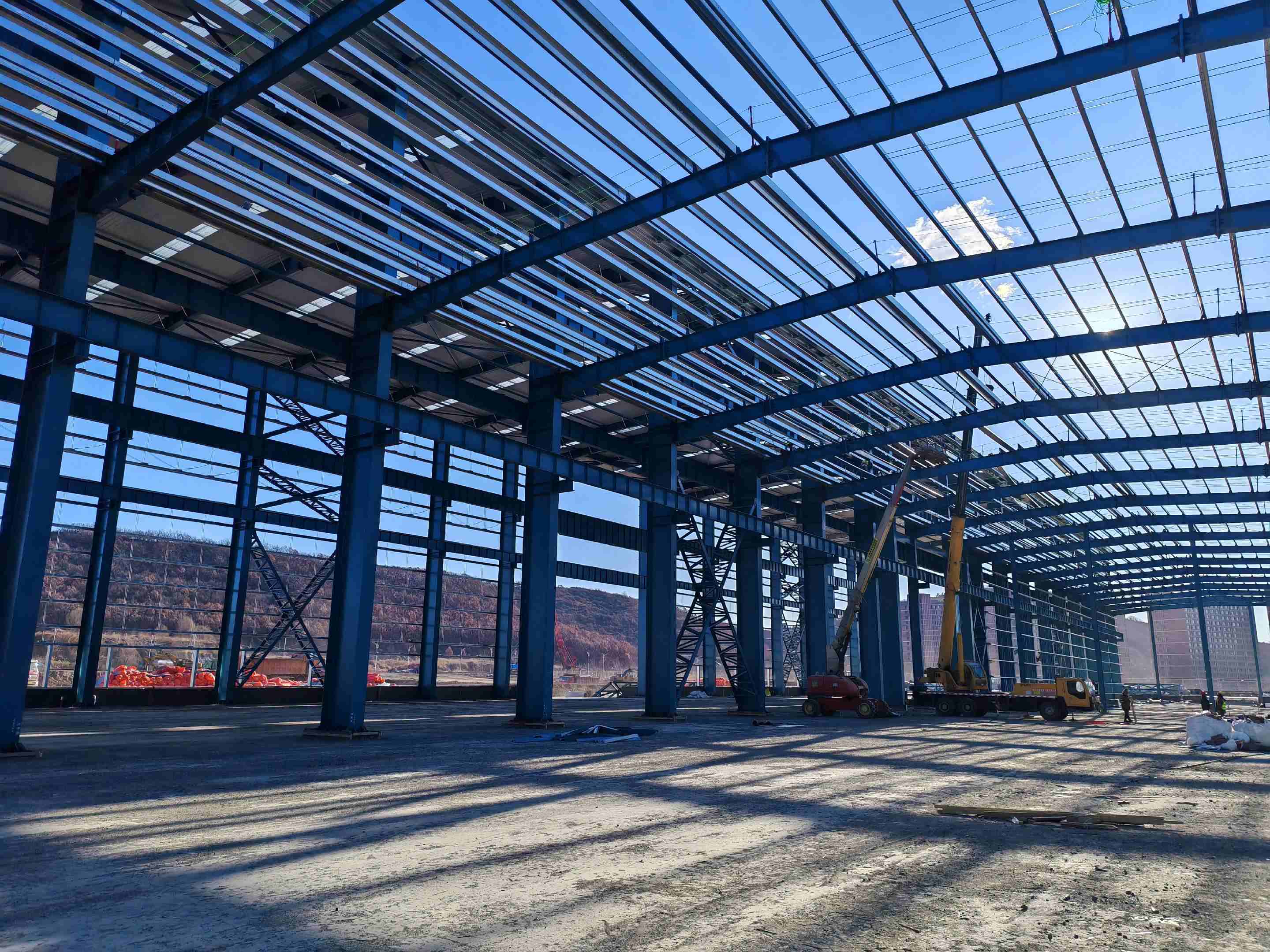
Direct integration of FEED engineering with shop CNC tooling reduces total structural tonnage by 8% to 15%. Direct collaboration between engineering designers and production facilities optimizes member sizing around standard mill rolling increments while rationalizing connection geometry to eliminate scrap and high-stress plate welding. Modeling columns and primary framing inside a unified Tekla Structures LOD 400 environment directly outputs machine-readable DSTV files to automated multi-axis beam drill lines and high-definition CNC plasma tables operating within tolerances of ±0.5 mm.
Single-source turnkey EPC accountability compresses structural delivery timelines by 15% to 25%. Detailing and fabrication proceed concurrently with raw material procurement rather than sequentially. Raw steel plates (ASTM A992 / GB/T 1591 Q355B) are ordered against nesting layouts while connection calculations are finalized per AISC 360-16 and AWS D1.1. In-house surface preparation to ISO 8501-1 Sa 2.5 shot-blast standards and automated airless application of 80 μm dry film thickness (DFT) epoxy zinc-rich primer occur in climate-controlled fabrication bays, eliminating weather delays and assuring long-term coating integrity prior to marine export packaging.
| Procurement Parameter | Traditional Multi-Vendor Model | Integrated Turnkey EPC Model | Technical and Commercial Impact |
|---|---|---|---|
| Detailing & Connection Engineering | Third-party drafting firm; isolated RFI cycles | Integrated Tekla LOD 400 connected directly to plant CNC | Eliminates 3 to 5 weeks of RFI coordination delay |
| Steel Tonnage Optimization | Over-designed framing based on generic tables | Custom finite element sizing matched to stock mill lengths | 8% to 15% reduction in total steel weight |
| Fabrication Tolerances | Disparate shop methods; cumulative variance up to ±5 mm | Automated multi-axis CNC drilling and cutting within ±0.5 mm | Eliminates field hole reaming and torch modifications |
| Surface Preparation & Coating | Subcontracted or job-site manual paint application | Enclosed automated Sa 2.5 blast with 80 μm epoxy primer | Verified coating adhesion per ASTM D4541 |
| Field Fit-Up & Rework Rate | 15% to 20% structural connections require modification | Under 1.5% site connection adjustment rate | Saves up to $180 per ton in site crane standby and hot works |
| Overall Delivery Schedule | Linear sequential execution with multiple handoffs | Parallel engineering, procurement, and fabrication | 15% to 25% delivery schedule compression |
Stage 1: Front-End Engineering Design (FEED) & Computational Load Modeling
During Front-End Engineering Design (FEED), operational plant requirements, mechanical equipment layouts, process piping runs, and material handling pathways are converted into three-dimensional mathematical frameworks. At Shandong XinQiao Steel Structure Co., Ltd., our engineering division executes this translation using advanced finite element analysis (FEA) software, specifically STAAD.Pro and ETABS. Specialized frame verifications run through SAP2000. Within an industrial steel structure turnkey design fabrication and supply contract, structural precision at the FEED stage dictates downstream material take-offs, connection typologies, shop fabrication workflows, and sub-slab foundation volumes.
Computational workflows construct a continuous mathematical representation of the facility. ASCE 7-22 and AISC 360-22 LRFD/ASD governing load combinations applied across finite element models establish member sizing and boundary conditions under gravity loads and extreme environmental actions. Primary dead loads integrate the self-weight of structural steel framing (ASTM A992 wide-flange shapes and built-up plate girders, alongside Q355B secondary purlins), composite floor systems, architectural metal cladding, and fixed industrial processing equipment. Collateral load allowances range between 0.25 kN/m² and 0.75 kN/m² for suspended building services, including cable trays and HVAC ductwork. Wind action calculations per ASCE 7-22 Directional Procedure incorporate basic wind speeds up to 180 mph, Exposure Categories C and D, internal pressure coefficients (GCpi = ±0.55 for partially enclosed process bays), and high local suction forces along roof eaves and wall corners. For facilities routing hot petrochemical or steam distribution, longitudinal thermal pipe friction forces are directly applied to the structural framing using friction coefficients of μ = 0.30 for steel-on-steel interfaces and μ = 0.10 for fluoropolymer (PTFE) slide bearings.
Dynamic material handling introduces severe cyclic stresses into structural framing. Crane runway fatigue calculations executed in compliance with AISE Technical Report No. 13 for Class D/E/F severe industrial service ensure crane girders and support bents withstand heavy continuous operations without cracking. Kinetic impact parameters dictate a 25% amplification on static vertical wheel reactions for cab-operated overhead bridge cranes, a lateral surge load equal to 20% of the combined lifted load and trolley weight distributed equally across runway rails, and a longitudinal tractive thrust calculated at 10% of maximum static wheel loads acting along the rail head. Runway girders operating under Class E and Class F duty are checked against stress range thresholds per AISC 360-22 Appendix 3, evaluating welded flange-to-web joints, stiffener terminations, and cope details against fatigue failure beyond 2 × 10⁶ stress cycles.
| Crane Classification | Operating Service Profile | Typical Span (m) | Runway Girder Profile | Max Vertical Deflection | Max Lateral Deflection | Fatigue Life Category |
|---|---|---|---|---|---|---|
| Class C (Moderate) | Machine shops, light assembly | 6.0 - 9.0 | Rolled W-beam with cap channel | L / 600 | L / 400 | Non-fatigue governed |
| Class D (Heavy) | Foundries, heavy fabrication | 9.0 - 12.0 | Welded plate girder with cap plate | L / 800 | L / 500 | AISC Category B / C |
| Class E (Severe) | Scrap processing, magnet cranes | 12.0 - 15.0 | Welded plate girder, full-pen web | L / 1000 | L / 600 | AISE TR-13 Class E |
| Class F (Continuous) | Continuous casting, ladle bays | 12.0 - 18.0 | Dual-web torsion box plate girder | L / 1200 | L / 800 | Critical fatigue (N > 2M) |
Lateral stability under extreme ground motions requires energy-dissipative framing. Seismic force-resisting systems (SFRS) detailed under AISC 341-22 for special concentrically braced frames (SCBF) and moment frames (SMF) balance drift mitigation with controlled ductile post-yield behavior. Braced frame elements require ASTM A500 Grade C structural tubing or ASTM A992 wide-flange members, designed to meet the strict width-to-thickness (λhd) limits of AISC 341-22 Table D1.1 to prevent premature local buckling under cyclic tension-compression cycles. Beam-to-column moment connections inside SMF configurations are modeled with reduced beam sections (RBS) or heavy shop-welded flange details, forcing the plastic hinge mechanism into the beam span away from the column face and weld access holes.
The interface between the superstructure and concrete foundation concludes the mathematical FEED scope. Anchor rod tension and shear capacity evaluated per ACI 318 Chapter 17 using ASTM F1554 Grade 55/105 embedments prevent non-ductile concrete failure modes under critical uplift and base shear combinations. FEA reaction envelopes govern analytical checks for steel rod tensile rupture, concrete breakout in tension, concrete side-face blowout, and concrete pryout. To reconcile engineering models with practical field installation, anchor rod layouts respect the AISC Design Guide 1 Section 2.3 erection tolerance of ±3 mm. Anchor clusters use heavy hex nuts and oversized base plate holes per AISC Manual Table 14-2, paired with ASTM A36 structural plate washers that are field-welded to the column base plate to ensure positive, direct shear transfer into the foundation pedestal.
Stage 2: Tekla BIM LOD 400 Connection Detailing & Direct-to-CNC Workflows
At Shandong XinQiao Steel Structure Co., Ltd., our industrial steel structure turnkey design fabrication and supply model relies on eliminating the traditional disconnect between engineering analysis and shop floor execution. Once structural member sizes are finalized in 3D frame analysis, the structural geometry transfers into Tekla Structures for Level of Development (LOD) 400 detailing. Tekla Structures LOD 400 models incorporate every stiffener, weld preparation bevel, bolt hole, and erection clearance. Every assembly is modeled to fabrication-level fidelity, including backing bars and weld access holes (rat holes) per AWS D1.1 Figure 5.2. This eliminates clash points between structural members and MEP runs before cutting the first plate.
Moment connections calculated per AISC 358-22 prequalified connection criteria and AISC Design Guide 4/16 form the primary lateral force-resisting assemblies across heavy industrial clear spans. We detail bolted extended stiffened (4ES and 8ES) end-plate configurations alongside Welded Unreinforced Flange-Welded Web (WUF-W) connections. For heavy industrial crane-runway columns and lateral braced bays, vertical bracing gusset plates sized via the Uniform Force Method (UFM) per AISC Steel Construction Manual Part 13 prevent secondary moments at the beam-to-column joints. The UFM controls the distribution of lateral forces to the work point, ensuring concentric axial transfer across the gusset-to-beam and gusset-to-column interfaces without inducing uncalculated prying forces or torsional eccentricities.
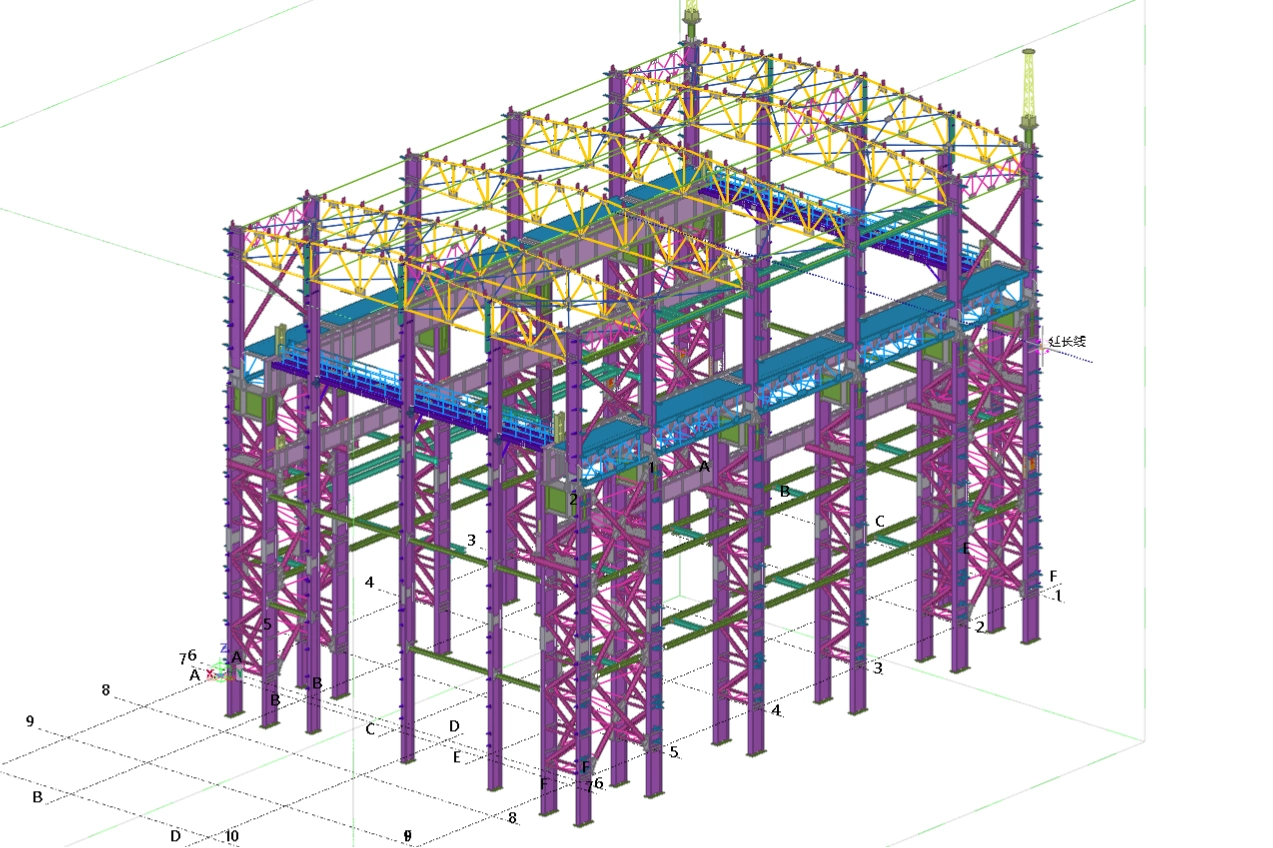
High-strength bolting engineered to RCSC specifications using ASTM F3125 Grade A325/A490 slip-critical assemblies governs our field connection performance. In crane-runway and seismic lateral frames, joints are engineered as slip-critical (Class A with clean mill scale or Class B blast-cleaned to SSPC-SP 10 / Sa 2.5 with approved zinc coatings), preventing hole elongation and joint slippage under dynamic load reversals. Standard single-plate shear tabs (Part 10 of the AISC Manual) require bearing connections with threads excluded from the shear plane (Grade A325-X) where static gravity dead and live loads govern.
| Connection Classification | Design Standard / Sizing Reference | Fastener or Weld Specification | Faying Surface / Weld Prep | Shop & Erection Tolerance Limits |
|---|---|---|---|---|
| Bolted Extended Stiffened End-Plate (4ES / 8ES) | AISC Design Guide 4 & 16 / AISC 358-22 | ASTM F3125 Grade A490 slip-critical; Class B slip coefficient (μ = 0.50) | SSPC-SP 10 / Sa 2.5 shot blast; zinc-rich primer ≤ 80 μm DFT | Hole location ±1.0 mm, end-plate tilt ≤ 1.5 mm |
| Welded Unreinforced Flange-Welded Web (WUF-W) | AISC 358-22 Section 8 / AWS D1.1 | Complete Joint Penetration (CJP) groove welds; AWS E7018 / E71T-1 electrodes | 30-deg bevel, 2 mm root face, 3 mm root opening; backing strip | Fit-up gap ±1.5 mm, angular bevel ±2.5 deg |
| Vertical Bracing Gusset | Uniform Force Method (AISC Manual Part 13) | Double shear ASTM F3125 Grade A325-N bolts with E70XX fillet welds | Blast-cleaned Sa 2.5; weld zone clean of primers | Gusset plane offset ≤ 1.5 mm, edge distance ±1.0 mm |
| Heavy Column Base and Splice | AISC 360-16 Chapter J / AISC Design Guide 1 | ASTM A354 Gr. BD or A36 anchor rods; Partial Joint Penetration (PJP) groove | Direct bearing surfaces milled to 1.6 μm Ra roughness | Milling gap ≤ 0.5 mm over 75% contact area; anchor pattern ±3.0 mm |
| Heavy Single-Plate Shear Tab | AISC Steel Construction Manual 15th Ed. Part 10 | ASTM F3125 Grade A325-X bearing; standard round holes | Shop primer excluded around bolt group for slip-critical variants | Hole center spacing ±0.5 mm, hole diameter +0.8 mm / -0 mm |
Direct export of DSTV/.NC1 machine language drives multi-axis CNC cutting and drilling cells with zero manual translation. The Tekla LOD 400 model outputs machine-readable numeric code in .NC1 and DSTV formats straight to automated multi-spindle drilling lines and plasma plate-processing systems. Toolpaths include automated beveling and scribe-marking for stiffener fit-up. CNC drilling maintains hole pitch accuracy within ±0.2 mm, while automated thermal cutting holds edge squareness and dimensional limits within ±0.5 mm. Removing manual drafting and hand-layout measurements from the workflow eliminates interface clashes and ensures field fit-up on site.
Stage 3: Metallurgy, Material Sourcing & EN 10204 3.1 Traceability Protocols
Procurement integrity dictates the structural performance and seismic resilience of high-hazard manufacturing plants. Within our industrial steel structure turnkey design fabrication and supply workflow, metallurgical quality control begins at the primary melt shop rather than the fabrication floor. Shandong XinQiao executes an uncompromising material verification framework aligned with AISC 360-16, AISC 341-16, and EN 1090-2 (Execution Class EXC3/EXC4) to guarantee that every structural member satisfies strict chemical and mechanical baselines before entering the processing line.
Core Metallurgical Specifications & Selection Criteria
Primary structural members specify ASTM A992 with yield strength of 50 ksi (345 MPa) and a controlled yield-to-tensile ratio ≤ 0.85 for seismic ductility. This controlled ratio provides predictable plastic hinge formation in moment frames without premature local flange buckling. For cold-climate installations or dynamic processing units subject to low-temperature embrittlement, fracture critical requirements govern: Charpy V-notch (CVN) impact toughness must reach at least 20 ft-lb at -20 °F (27 J at -20 °C), extending to 27 J at -40 °C for arctic-grade specifications.
Heavy built-up plate components require ASTM A572 Grade 50 or EN 10025-2 S355J2+N with Charpy V-notch impact testing down to -20°C / -40°C. Hollow structural sections (HSS) for primary bracing and pipe racks mandate ASTM A500 Grade B or Grade C, maintaining seam-weld integrity verified via continuous eddy-current or ultrasonic testing during tube production. Base plates and secondary shear tabs use ASTM A36, balancing weldability with ductile load distribution to foundation anchor systems.
| Material Grade | Standard & Delivery Condition | Yield Strength Fy min (MPa) | Tensile Strength Fu (MPa) | CVN Impact Energy (Min) | Max Yield Ratio (Fy/Fu) | Typical Industrial Application |
|---|---|---|---|---|---|---|
| ASTM A992 | ASTM A992 / Hot-Rolled | 345 (50 ksi) | 450 - 585 | 27 J at -20 °C | ≤ 0.85 | Seismic moment frames, primary crane runway girders |
| ASTM A572 Gr 50 | ASTM A572 / Normalized | 345 (50 ksi) | 450 min | 27 J at -20 °C | ≤ 0.88 | Heavy built-up plate columns, crane brackets |
| S355J2+N | EN 10025-2 / Normalized | 355 | 470 - 630 | 27 J at -20 °C | Not mandated | International export portal frames, heavy trusses |
| S355NL | EN 10025-3 / Norm. Rolled | 355 | 470 - 630 | 27 J at -50 °C | Not mandated | Sub-zero industrial storage, cryogenic rack piping |
| ASTM A500 Gr C | ASTM A500 / Cold-Formed | 345 (50 ksi) | 427 min | Project specific | Not mandated | Perimeter wind columns, vertical chevron bracing |
| ASTM A36 | ASTM A36 / As-Rolled | 250 (36 ksi) | 400 - 550 | Optional / Commercial | Not mandated | Column base plates, non-critical clip angles |
Through-Thickness Ductility: Lamellar Tearing Mitigation
High weld restraint in heavy welded tee and cruciform joints induces severe through-thickness shrinkage strains, risking sub-surface delamination. Thick plate connections require ASTM A770 Z35 through-thickness reduction-of-area testing to eliminate lamellar tearing risk under high weld restraint.
For plates exceeding 40 mm (1.57 inches) incorporated into full-penetration groove-welded beam-to-column connections, we mandate ASTM A770/A770M supplementary requirements with a minimum 35% reduction of area (Z35) across three through-thickness tensile test specimens. In tandem, ultrasonic testing per ASTM A578/A578M Level II is conducted across all weld-heat-affected zones prior to cutting, detecting internal laminations, non-metallic inclusions, or micro-voids formed during ingot solidification.
EN 10204 Type 3.1 Traceability & Positive Material Identification (PMI)
Material authenticity verified by 100% EN 10204 Type 3.1 inspection certificates matching every steel plate and profile heat number. Our Quality Assurance department cross-references the chemical composition (carbon equivalent values CEIIW ≤ 0.43% or Pcm ≤ 0.28% per AWS D1.1 Clause 3) and mechanical test results against mill certificates before material discharge into inventory.
- ▪ Hard Stamping & Tracking: Every plate and profile receives a deep-die stamp recording the heat batch, project ID, and plate identification number, ensuring physical traceability through automated CNC nesting (cutting tolerance within ±0.5 mm).
- ▪ Spectroscopic Verification: Portable XRF Positive Material Identification (PMI) confirms metallurgical chemistry prior to cutting. Handheld X-ray fluorescence analyzers verify key alloying elements (manganese, silicon, chromium, nickel, molybdenum, and vanadium) on 100% of high-strength structural nodes, preventing grade mix-ups in the storage yard and assuring absolute preheat compliance during welding.
Stage 4: Advanced CNC Fabrication, Beam Processing & SAW Gantry Welding
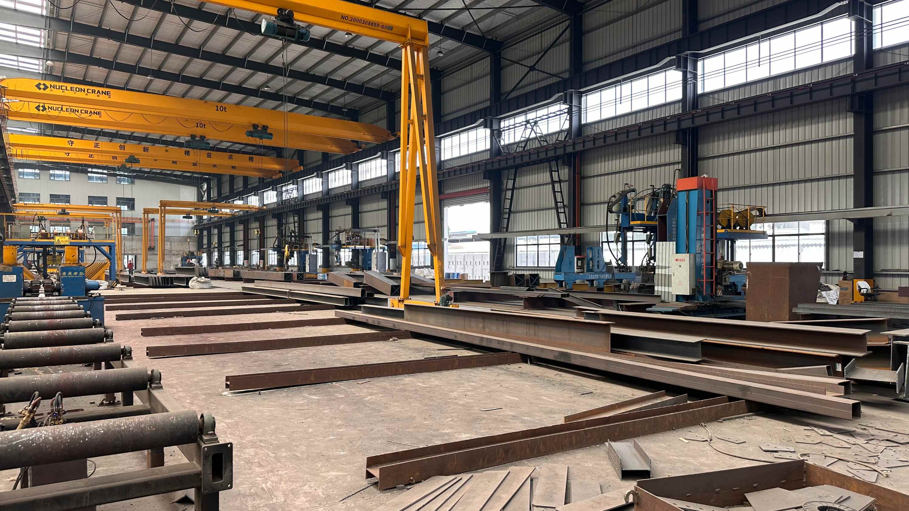
Heavy industrial projects demand strict physical execution inside the automated manufacturing facility. Within an industrial steel structure turnkey design fabrication and supply workflow, shop-floor operations transform structural mill shapes and heavy plate into high-integrity components. Production begins with primary raw material staging under ISO 9001 quality tracking, transitioning raw ASTM A572 Grade 50 and Q355B plates directly onto heavy thermal cutting beds.
CNC Thermal Processing and Edge Preparation
Plate profiling relies on dual-side drive CNC gantry systems utilizing high-definition plasma alongside multi-torch oxy-fuel systems. Oxy-fuel cutting heads handle plate thicknesses from 25 mm up to 150 mm using high-purity oxygen and natural gas or propane cutting streams. For web and stiffener assemblies below 32 mm, high-definition plasma units running at 400 amps cut with oxygen or nitrogen-shielded plasma arcs. Gusset assemblies below 32 mm follow identical plasma cutting parameters.
Multi-axis CNC plasma and oxy-fuel cutting systems achieve cut tolerances within ±1.0 mm with automated weld bevel profiling. The integrated bevel heads execute real-time single-bevel (V), double-bevel (X), and K-groove joint preparations directly on plate margins per AWS D1.1 and EN 1090-2 execution standards. Automated beveling eliminates secondary edge grinding, establishing root face and groove angles matching qualified Welding Procedure Specifications (WPS).
3D Robotic Beam Processing and Multi-Spindle Drilling
Rolled W-sections, wide-flange columns, and structural tees move via automated roller conveyors to 3D robotic coping stations and multi-spindle carbide drill lines. Direct post-processing translates Tekla Structures DSTV (.NC1) models into machine tool paths without manual programming steps.
Automated multi-spindle carbide drill lines eliminate mechanical punch distortion, maintaining hole location precision within ±0.5 mm. Conventional hydraulic punching induces localized plastic strain and micro-cracking in the hole periphery, which impairs structural fatigue life. Three-axis independent drill heads equipped with internal through-tool cooling drill both flanges and the structural web simultaneously, executing hole drilling, blind-hole tapping, and countersinking in a single pass. Part scribing and assembly marks are directly etched by CNC machinery to guarantee error-free fit-up. Layout marks, stiffener placement indicators, weld IDs, and part identification numbers are stamped or laser-etched into the steel surface, eliminating measuring tape errors during mechanical assembly.
Built-Up Plate Girders and Tandem SAW Gantry Systems
For heavy processing buildings, wide-span logistics bays, and crane systems carrying heavy electric overhead traveling (EOT) bridge cranes, rolled sections are insufficient. Automated assembly lines fixture three-plate girders, box columns, and variable-depth tapered sections using heavy hydraulic alignment clamps to enforce orthogonality.
Submerged Arc Welding (SAW) gantry systems deliver continuous Complete Joint Penetration (CJP) welds on plate girders up to 3 meters web depth. Gantry welding carriages operate tandem-wire configurations (lead wire DC+ for deep penetration; trail wire AC for bead widening and crown leveling) submerged under granular fused or agglomerated flux. Operators balance welding parameters to restrict weld heat input between 1.8 and 2.6 kJ/mm, maintaining mechanical toughness in the heat-affected zone (HAZ):
- Lead Wire: 700 to 850 A, 30 to 34 V, Direct Current Electrode Positive (DCEP)
- Trail Wire: 600 to 750 A, 32 to 36 V, Alternating Current (AC)
- Travel Speed: 450 to 650 mm/min depending on flange thickness and fillet throat size
Strict preheat and interpass temperatures are maintained per AWS D1.1 Table 5.8 to prevent hydrogen-induced cold cracking in high-strength steels. Induction heating or multi-flame ceramic gas heaters heat thick flange plates (thicknesses over 38 mm) to target preheat thresholds (typically 65 to 150 °C based on carbon equivalent values) verified through digital surface pyrometers prior to arc strike. Mechanical run-on and run-off tabs isolate arc strike defects and crater piping away from finished structural member boundaries.
| Operation / Joint Category | Material Specification | Equipment Used | Process Parameters | Acceptance Standard / Tolerance |
|---|---|---|---|---|
| Plate Profiling and Beveling | ASTM A36 / A572 Gr 50, 10 to 120 mm | CNC Dual-Gantry Oxy-Fuel / HD Plasma | 400A Plasma / Cutting O2: 0.7-0.9 MPa | ±1.0 mm (ISO 9013 Class 2) |
| Structural Flange / Web Drilling | ASTM A992 / Q355B, W14 to W44 Shapes | 3-Axis Multi-Spindle Carbide Drill Line | 1,800-2,400 RPM, Through-tool MQL | Hole centers: ±0.5 mm, Dia: +0.2/-0.0 mm |
| Web-to-Flange Built-Up Welds | Heavy Plates (up to 80 mm Flange Thickness) | Twin-Wire SAW Gantry Tractor | 1,300 to 1,600 A total, Heat: 2.2 kJ/mm | AWS D1.1 CJP / Prequalified WPS, 100% UT |
| Box Column Longitudinal Seams | Heavy Structural Plate, 25 to 60 mm | Multi-Pass SAW with Ceramic Backing | Lead DC+ 750A / Trail AC 680A, Interpass: 150°C | Zero undercut > 0.5 mm, Full ultrasonic |
| Beam Coping and Web Penetrations | AISC W-Shapes, Channels, Hollow Sections | 6-Axis Robotic Thermal Coping Cell | High-Definition Oxygen Plasma, 260A | AISC 303-16 Sec 6.4, Coping: ±1.5 mm |
Following SAW completion, heavy built-up members run through mechanical flange straightening machines to eliminate angular weld shrinkage, aligning flange squareness within AISC 303 tolerances before moving to non-destructive testing (NDT).
See what we would find
During structural feasibility audits, our engineering desk regularly identifies opportunities to reduce member weight while maintaining frame stiffness and wind load compliance. Operating from our 60,000 sqm fabrication facility with automated CNC cutting lines, we maintain sub-millimeter tolerances governed by AISC 360 and AWS D1.1 standards.
Stage 5: Quality Assurance: AWS D1.1 Welding Codes & NDT Examination Protocols
For high-consequence projects, rigorous shop quality control defines the boundary between structural failure and multi-decade serviceability. Shandong XinQiao executes industrial steel structure turnkey design fabrication and supply under an audited Quality Management System aligned with AWS D1.1/D1.1M:2020 and ISO 3834-2. Welding operations do not proceed on standard shop assumptions; all welding executed strictly under qualified WPS backed by mechanical PQR tensile and bend tests per AWS D1.1 Clause 6.
Each Welding Procedure Specification (WPS) details essential variables including joint geometry, base metal groupings (ASTM A992, ASTM A572 Gr 50, or EN 10025-2 S355JR/J2), filler metal classifications, shielding gas mixtures, minimum preheat temperatures per AWS D1.1 Table 5.8, and interpass temperature limits (capped at 230 degrees Celsius for high-strength low-alloy steels). Procedure Qualification Records (PQRs) document physical testing verified by accredited independent metallurgical laboratories, comprising transverse tension tests, all-weld-metal tension specimens, and root, face, or side bend tests. Welder qualifications maintained under active continuity logs per AWS D1.1 Clause 6 / ISO 9606-1 ensure that every welder and automated welding operator is certified for the specific position, process, thickness range, and electrode classification used on the production floor. Requalification is required if an operator does not use a specific process for six months.
Shop fabrication relies on three high-deposition, semi-automated and automated welding processes:
- Submerged Arc Welding (SAW / Process 121): Utilized on automated twin-arc gantry lines for built-up H-section and box-column longitudinal seams, pairing AWS A5.17 EM12K solid wire with neutral active fluxes to guarantee minimum impact toughness of 27 Joules at -20 degrees Celsius.
- Gas-Shielded Flux-Cored Arc Welding (FCAW-G / Process 136): Applied on primary moment connections, stiffener plates, and heavy clip angles using AWS A5.20 E71T-1C / E71T-9C wire with 100% CO2 or 75/25 Argon/CO2 shielding for superior bead wetting and positional capability.
- Gas Metal Arc Welding (GMAW / Process 135): Used on light cold-formed girt clips, purlin struts, and secondary brackets using AWS A5.18 ER70S-6 solid wire under 80/20 Argon/CO2 shielding gas.
Non-destructive testing (NDT) is structured around weld criticality, cyclic loading stress states, and stress concentration risks. Visual Testing (VT) is conducted across 100% of all shop welds by certified AWS Certified Welding Inspectors (CWI) in accordance with AWS D1.1 Clause 8.1. Magnetic Particle Testing (MT) per ASTM E709 and Dye Penetrant Testing (PT) per ASTM E165 evaluate root pass sound metal after carbon-arc gouging on double-welded joints, coped beam access holes, and heavy fillet terminations to detect surface and near-surface cracking.
Volumetric examination targets Complete Joint Penetration (CJP) groove welds subjected to high fatigue and dynamic loads. 100% of all CJP moment connections and crane girder tension flange welds undergo volumetric Ultrasonic Testing (UT) or Phased Array UT (PAUT). Conventional UT follows AWS D1.1 Clause 8, Annex O, utilizing calibrated IIW reference blocks to quantify discontinuity reflection levels (decibel ratings) against defect acceptance thresholds. For heavy thicknesses exceeding 32 mm, Phased Array Ultrasonic Testing (PAUT) per ASTM E2700 provides encoded, multi-angle S-scan imaging to map sidewall lack of fusion, slag inclusions, and porosity without the radiation hazards and shop work stoppages associated with Radiographic Testing (RT per ASTM E94).
| Joint Type and Location | Welding Process | NDT Inspection Scope | Volumetric NDT Method | Acceptance Criteria |
|---|---|---|---|---|
| Built-up Primary Column Flange-to-Web CJP | SAW (Process 121) | 100% VT + 20% MT Root/Cap | 100% UT / PAUT | AWS D1.1 Table 8.2 (Static) |
| Crane Girder Tension Flange Butt Welds CJP | SAW / FCAW-G | 100% VT + 100% MT Cap | 100% UT / PAUT + Spot RT | AWS D1.1 Table 8.3 (Cyclic) |
| Beam-to-Column Moment Flange Splices CJP | FCAW-G (Process 136) | 100% VT + 100% MT Root/Cap | 100% UT or PAUT | AWS D1.1 Table 8.2 (Static) |
| Heavy Crane Stiffener & Diaphragm Fillets | FCAW-G (Process 136) | 100% VT + 25% MT | Spot UT on plates over 25 mm | AWS D1.1 Table 8.1 (Visual) |
| Secondary Framing Purlin / Girt Bracket Fillets | GMAW (Process 135) | 100% VT + Random 5% PT | None (Visual Verification Only) | AWS D1.1 Table 8.1 (Visual) |
Dimensional Tolerances & Camber Verification
Dimensional control verified against AISC 303-22 camber and sweep tolerances prior to surface treatment prevents field erection delays. Total member length is verified during the same pre-treatment stage. Final member geometry is measured with calibrated 3D total stations and laser trackers immediately following weld cooling. Dimensional acceptance thresholds strictly enforce:
- Member overall length: ±1.5 mm for members with both ends finished for contact bearing; ±2.0 mm for non-bearing structural members under 9 meters; ±3.0 mm for members exceeding 9 meters.
- Camber: 0 to +6 mm deviation from specified fabrication profile for roof girders and trusses. Crane runway girders require camber tolerances within 0 to +5 mm to maintain bridge crane rail elevation.
- Sweep: Maximum deviation of 1 mm per 1,000 mm of member length, limited to a total of 10 mm along the full span.
- Cross-sectional geometry: Flange out-of-squareness held within ±3.0 mm or b/200 (whichever is greater), and web center deviation within ±3.0 mm off the flange centerline per EN 1090-2 Execution Class 3 (EXC3).
Before steel components enter the automated shot-blasting booth for Sa 2.5 preparation, fabrication documentation compiled into a Quality Dossier (MTRs, NDT reports, CWI sign-offs, as-built dimensional logs) verifies heat trace identification back to rolling certificates per EN 10204 Type 3.1. This quality record protects the asset owner against non-compliant steel and confirms that field installation meets design requirements.
Stage 6: Surface Preparation (SSPC-SP 10 / Sa 2.5) & ISO 12944 Protective Coating Systems
Corrosion protection engineering dictates the operational lifespan of heavy industrial infrastructure exposed to chemical vapors, maritime salt spray, and extreme thermal cycling. At Shandong XinQiao Steel Structure Co., Ltd., industrial steel structure turnkey design fabrication and supply requires systematic execution of protective coatings directly integrated with our factory production lines. Surface preparation and paint application operate under strict environmental and mechanical protocols to eliminate early delamination, osmotic blistering, and under-film corrosion creep.
Automated Centrifugal Blasting & Surface Profile Topography
All structural profiles, fabricated plate girders, and secondary members pass through automated roller-conveyor centrifugal blast machines housing 8 to 12 direct-drive blast wheels. Manual compressed-air nozzles process complex built-up geometries and connection nodes using pressure-fed blast pots. Surface blast cleaning certified to SSPC-SP 10 / NACE No. 2 / Sa 2.5 with controlled 50–75 μm angular anchor profile removes all mill scale, rust, welding slag, and foreign contaminants.
Abrasive media selection relies on an engineered operating mix containing 70% chilled cast steel grit (GL25/G40) and 30% spherical steel shot (S280/S330). The spherical shot cleans the base plane through impact energy, while the angular grit cuts a high-density mechanical anchor pattern. Surface roughness is inspected on every shift using ASTM D4417 Method B digital profile gauges and Method C replica tape (Coarse and X-Coarse Press-O-Film) to guarantee a peak-to-valley height strictly between 50 and 75 μm (2.0 to 3.0 mils). Water-soluble salt contamination on the blasted steel is verified per ISO 8502-6 (Bresle method) and ISO 8502-9, maintaining total conductivity below 20 mS/m (chloride content below 30 mg/m²).
Climate Control in Enclosed Coating Bays
Blasted steel transfers immediately to climate-controlled painting bays equipped with desiccant dehumidifiers and indirect-fired makeup air units. Paint application strictly governed by ISO 12944 environmental parameters: steel temperature at least 3°C above dew point and relative humidity below 85%.
Environmental data logging monitors ambient dry-bulb temperature, wet-bulb temperature, relative humidity, dew point, and steel substrate temperature continuously using calibrated electronic hygrometers and surface magnetic contact thermometers compliant with ISO 8502-4. Application terminates instantly if ambient temperatures fall below 10°C (50°F) or exceed 38°C (100°F), or if wind velocities in open transit bays exceed 15 km/h, preventing solvent flash-off defects, pinholing, and dry-spray textures.
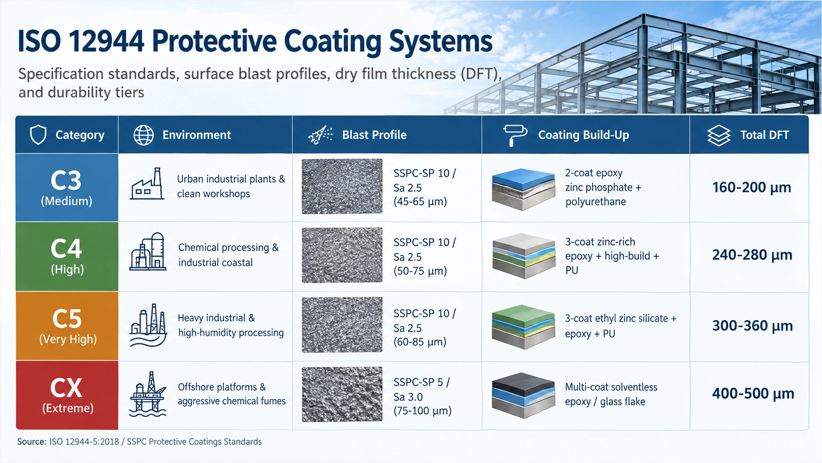
| Corrosivity Category (ISO 12944-2) | Atmospheric Environment & Typical Exposure | Surface Preparation Standard | Primer Coat Technology & Nominal DFT | Intermediate Tie-Coat Technology & Nominal DFT | Finish Topcoat Technology & Nominal DFT | Total Nominal System DFT | Expected Durability Range |
|---|---|---|---|---|---|---|---|
| C3 (Medium) | Urban areas, light industrial manufacturing, medium SO2 | ISO 8501-1 Sa 2.5 / SSPC-SP 10 | Zinc-rich epoxy (60 to 75 μm) | Polyamide high-build epoxy (100 to 125 μm) | Aliphatic acrylic polyurethane (50 to 60 μm) | 210 to 260 μm | Very High (> 25 years) |
| C4 (High) | Industrial plants, coastal areas with moderate salinity | ISO 8501-1 Sa 2.5 / SSPC-SP 10 | Zinc-rich epoxy (75 to 80 μm) | High-solids epoxy MIO tie-coat (125 to 150 μm) | Aliphatic acrylic polyurethane (50 to 75 μm) | 250 to 305 μm | High (15 to 25 years) |
| C5 (Very High) | Chemical plants, coastal and offshore docks with severe salt | ISO 8501-1 Sa 2.5 / SSPC-SP 10 | Ethyl silicate inorganic zinc (75 to 90 μm) | Cycloaliphatic amine epoxy (150 to 175 μm) | High-solids polysiloxane (60 to 75 μm) | 285 to 340 μm | Very High (> 25 years) |
| CX (Extreme) | Offshore marine platforms, splash zones, acid/alkali processing | ISO 8501-1 Sa 3 / SSPC-SP 5 | Solventless aromatic zinc epoxy (80 to 100 μm) | High-build surface tolerant MIO (175 to 200 μm) | Fluoropolymer / Polysiloxane (75 to 90 μm) | 330 to 390 μm | High (15 to 25 years) |
Protective coating systems engineered for C4/C5-M atmospheric corrosivity deliver 15+ to 25+ years durability (Very High / H durability tier per ISO 12944-1:2017). The primary barrier relies on high-solids zinc-rich epoxy or ethyl silicate inorganic zinc primer containing at least 80% metallic zinc by weight in the dry film per SSPC-Paint 20 Level 1. This layer provides galvanic protection to the iron matrix. The intermediate high-build polyamide or polyamine epoxy incorporates micaceous iron oxide (MIO) lamellar pigment to lengthen the moisture permeation path. The exterior topcoat of aliphatic acrylic polyurethane or hybrid polysiloxane maintains gloss retention, color stability, and UV resistance under heavy solar exposure.
Passive Fire Protection & Hot-Dip Galvanizing
Where architectural requirements or process plant safety specify passive fire protection (PFP), intumescent coatings certified under UL 263, ASTM E119, and BS 476 Parts 20-21 apply directly over compatible, approved epoxy primers. Intumescent film thicknesses range from 800 μm up to 6,000 μm DFT, calculated precisely using section factor tables (W/D or Hp/A ratios) to achieve 60, 90, or 120-minute structural ratings.
For outdoor utility structures and pipe racks, hot-dip galvanizing per ASTM A123 / ISO 1461 provides corrosion protection. Structural sections pass through caustic degreasing, hydrochloric acid pickling, flux immersion in zinc ammonium chloride, and hot-dip immersion in a molten zinc bath maintained at 445°C to 455°C (833°F to 851°F). The resulting iron-zinc alloy layers develop through the Gamma and Delta phases beneath the Zeta phase. Topped by the pure Eta zinc outer skin, these layers yield a minimum average coating thickness of 85 to 100 μm for steel plates thicker than 6.0 mm.
Each spot represents the mathematical average of 3 gauge readings within a 40 mm diameter circle.
Area average ≥ Specified Nominal DFT. No individual spot may fall below 80% or exceed 120% of design limit.
Calibrated electronic magnetic gauges verified against certified shims on representative blast profiles.
Adhesion strength validated via ASTM D4541 pull-off testing achieving minimum failure limits of 5 to 7 MPa. Inspectors adhere 20 mm aluminum dollies to blast-cleaned, fully cured coating assemblies using a two-component structural epoxy adhesive. After a 24-hour cure at 23°C, a portable hydraulic pull-off adhesion tester (Type IV or V) applies a perpendicular tensile force at a controlled rate below 1 MPa/second until fracture occurs. Inspection records confirm failure occurs within the primer body (cohesive failure) rather than across the steel-primer interface (adhesive failure), documenting uncompromising surface bonding before structural dispatch.
Stage 7: Modular Trial Assembly, Export Packing, and Global Site Delivery Staging
The execution phase of industrial steel structure turnkey design fabrication and supply requires pre-shipment dimensional verification and rigorous sea-fastening engineering. Transporting high-tonnage structural packages across international maritime routes introduces severe dynamics, including three-axis vessel motion, marine atmospheric corrosion, and tight jobsite laydown constraints. Structural integrity at the jobsite begins in the fabrication shop with physical and digital pre-assembly protocols that verify theoretical geometry against real-world mill tolerances.
Pre-Shipment Quality & Transport Pipeline
- • Physical: 3-bent mock-up with ≥40% drift pins per AISC 303
- • Digital: Terrestrial LiDAR scan vs Tekla model (<1.5mm variance)
- • VCI plastic film + high-density polyethylene edge guards
- • ISPM-15 kiln-dried heat-treated timber + neoprene strips
- • 40HC: Linear columns/purlins (≤11.85m)
- • 40OT/40FR: Top-loaded heavy crane girders & wide trusses
- • Reverse container packing mapped to erection tier sequence
- • Direct offload to crane hook eliminating double-handling
Pre-Shipment Quality Verification: Physical Fit-Up and Digital Photogrammetry
To prevent mismatched field splices, multi-tier industrial frames undergo scheduled trial assemblies before application of finish coatings. Complex structural connections undergo physical trial fit-up or high-density 3D laser scan trial assembly to guarantee zero site clashes. For complex moment frames, heavy pipe racks, and transfer trusses, shop teams assemble adjacent bents using at least 40 percent drift pins and erection bolts per AISC 303-16 Section 7.13. Bolt holes must align within standard tolerances, ensuring that standard ASTM A325 or ASTM A490 structural bolts insert perpendicular without reaming or thermal slotting.
Where yard space restricts continuous physical trial assemblies of extended bridge girders or roof spans exceeding 48 meters, digital trial assembly provides the primary verification baseline. Industrial terrestrial LiDAR scanners (operating at millimeter-level accuracy per 10 meters) scan the shop-fabricated elements. Technicians superimpose the resulting dense point cloud data directly over native Tekla Structures solids models. Spatial deviation heat-maps identify camber variances, out-of-square base plates, or stiffener clashes exceeding the limits of AWS D1.1 and EN 1090-2 Class EXC3, allowing for targeted shop adjustments before elements reach the blast-and-paint line.
Export Containerization, Sea-Fastening, and Breakbulk Engineering
Export logistics dictate framing economics. Cargo containerization relies on 40ft High-Cube, Open Top, and Flat Rack equipment to minimize ocean freight volume charges. Structural components are engineered to standard shipping lengths wherever practical (under 11.85 meters for standard 40ft High-Cube containers). Deep built-up crane girders, stepped mill columns, and pre-assembled open-web trusses require top-loading into 40ft Open Top containers with removable soft tarpaulins, or securing onto 40ft Flat Rack containers for out-of-gauge widths exceeding 2.35 meters. Girders measuring between 18 and 28 meters route to breakbulk holds, requiring custom lifting lug calculations and marine surveyor hold-stowage plans.
| Shipping Mode / Equipment Type | Maximum Usable Payload Dimensions (L x W x H) | Maximum Safe Cargo Payload | Securing and Sea-Fastening Protocol | Typical Industrial Steel Structural Components |
|---|---|---|---|---|
| 40ft High-Cube Container (HC) | 11.85m × 2.34m × 2.68m | 26,500 kg | Engineered timber dunnage, 32mm steel strapping, welded deck clips | Standard columns, rolled rafters, purlins, girts, bracing struts |
| 40ft Open Top Container (OT) | 11.85m × 2.34m × 2.32m | 26,000 kg | Vertical load spreaders, web-clamped timber shores, top tension lashing | Heavy plate girders, stepped crane columns, rigid rafter haunches |
| 40ft Flat Rack (FR) | 11.65m × 2.20m × 2.24m | 39,000 kg | Turnbuckles, heavy-duty chains (Grade 70), welded stoppers to corner posts | Wide pipe rack bents, box columns, modular stair towers |
| Breakbulk Hold Stowage | Hold specific (up to 30.0m) | Exceeding 45,000 kg | Wire rope lashings, fabricated steel saddles, deck welded stoppers | Heavy bridge crane girders, clear-span roof trusses (> 24m) |
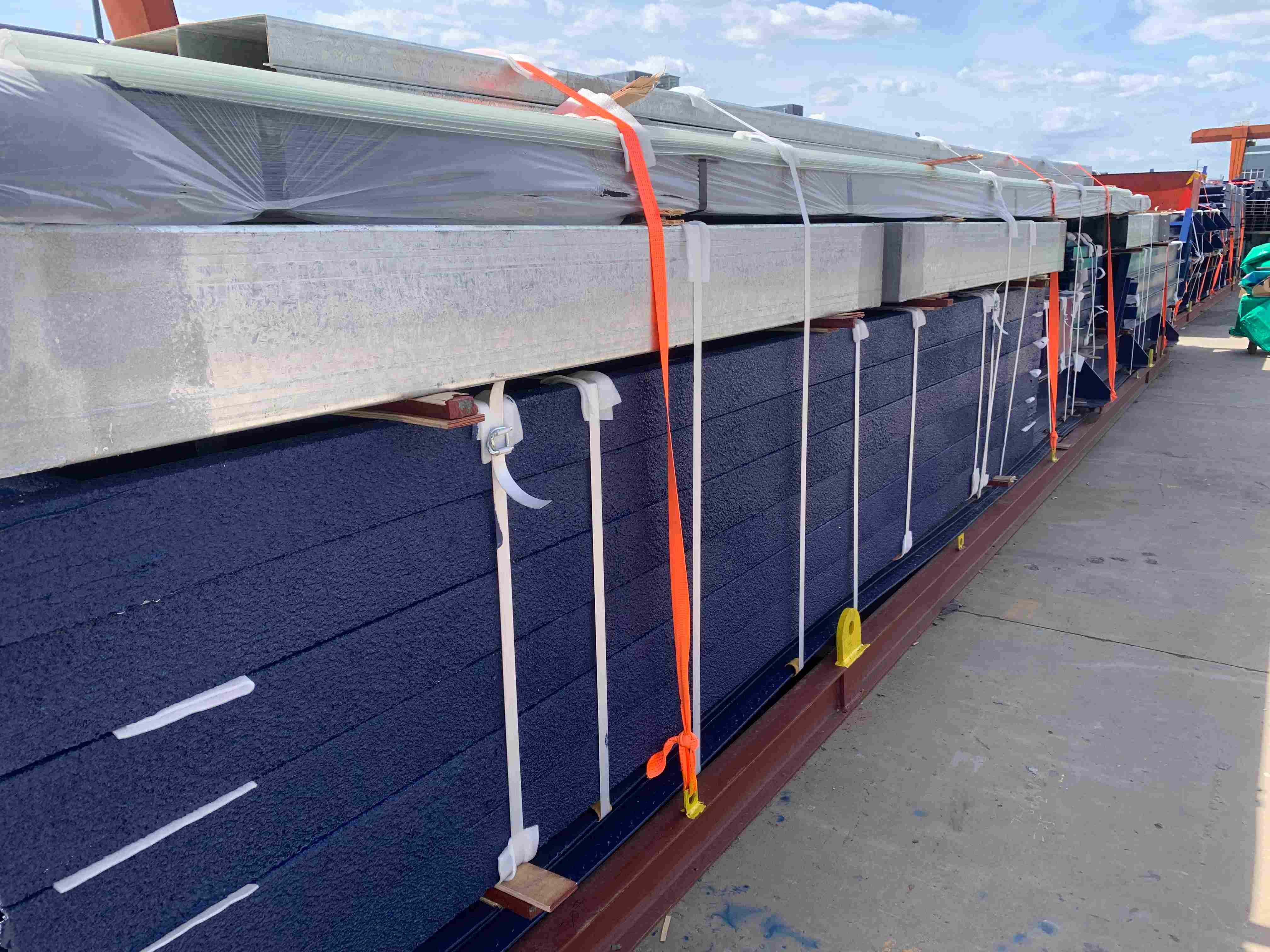
Export structural elements require engineered dunnage, steel strapping, and flange protectors conforming to IMO/ILO/UNECE cargo packing codes. Finished paint coats (such as 80 μm epoxy zinc-rich primer with 150 μm polyurethane topcoats) remain vulnerable to transit abrasions. Flange contact points require high-density polyethylene edge guards and oil-tempered hardboard separators. Machined bearing surfaces on column base plates and mill-to-bear joints receive a spray-applied film of vapor corrosion inhibitor (VCI) compound prior to wrapping in heavy multi-layer industrial barrier film. All wood blocking, dunnage, and cradles strictly comply with ISPM-15 heat-treatment standards to prevent quarantine delays at arrival ports.
Erection-Sequenced Loading and Tekla 4D Site Staging
Random container loading leads to site congestion and costly crane downtime. Structural piece marks and color-coded labels mapped directly to Tekla 4D site erection sequences to streamline offloading and crane erection staging. Every piece mark is cross-referenced to a master database that matches the shipping manifest, container number, package bundle, and site erection tier. Barcoded and QR-coded weather-resistant synthetic labels are applied adjacent to primary component marks, enabling receiving teams to scan elements using handheld inventory terminals.
Anchor Bolts & Primary Columns
Pack: Level 01 Plinth Anchor • Laydown: Direct Pick Grid A-D
Crane Runways & Main Rafters
Pack: Frame Bents 1 to 4 • Laydown: Crane Hook Pick Bay
Fabrication facilities pack containers in reverse order of field installation. The first column sections required at Grid A-1 occupy the door side of Container 01, while secondary cross-bracing elements occupy lower tiers or subsequent containers. As shipments arrive on site, mobile cranes pick structural steel members directly from containers or flat racks into active erection bays. This planned delivery flow eliminates double handling, minimizes laydown yard footprints, protects coatings from site dirt, and maintains crane hook uptime during field erection.
Heavy Industrial Structural Steel vs. Pre-Engineered Buildings (PEB): Technical Evaluation Matrix
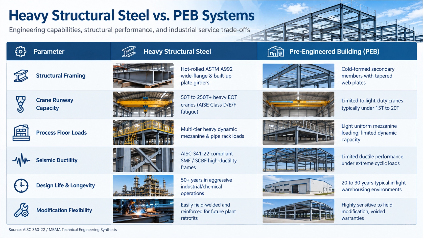
When executing an industrial steel structure turnkey design fabrication and supply contract, engineering teams must evaluate whether a facility belongs in a standard Pre-Engineered Building (PEB) framework or a heavy industrial structural framing scheme. PEB systems offer capital expenditure savings for low-load warehousing and distribution centers. However, primary processing plants, smelters, rolling mills, and complex chemical facilities impose operational conditions that exceed the structural threshold of lightweight cold-formed shapes and tapered thin-web rafters.
Heavy structural steel systems accommodate heavy crane duties (AISE TR 13 Class D/E/F, 50+ tons) where lightweight PEB cold-formed web members experience premature fatigue failure. Thin PEB web profiles, often detailed with slenderness ratios (h/tw) exceeding 200 to strip dead weight, develop severe out-of-plane web flexing under repeated cyclic hook loads. In contrast, heavy industrial mill buildings require submerged arc welded (SAW) plate girders and heavy rolled sections proportioned to AISC 360-16 compact member limits. Their flanges and webs (often 16 mm to 50 mm or thicker) prevent cyclic distortion and accommodate dynamic impacts without micro-cracking at beam-to-column welded connections.
Frame lateral deflection and drift in heavy structural steel are strictly controlled to H/400 to H/600 to prevent crane binding and piping joint leaks. Lightweight PEB portal frames are engineered to flexible drift thresholds of H/100 to H/200 under ASCE 7-22 wind actions. While acceptable for sheeted sheds, this degree of lateral sway causes crane runway girder misalignment, wheel flange wear, rail clip fatigue, and flange rupture along rigid process piping. Heavy industrial designs eliminate excessive drift through braced bays of heavy structural tees or wide flanges (ASTM A992 or Q355B/D) and fixed column base shoes anchored by assemblies installed to ±3 mm field tolerance.
Thick plate structural members (> 10 to 50 mm) withstand aggressive industrial chemical environments and support heavy cementitious or intumescent fireproofing, unlike light-gauge PEB panels. When exposed to chemical fumes or salt air, the light cold-formed purlins (1.5 mm to 2.5 mm) typical of PEBs can experience rapid structural loss once secondary galvanization degrades. Heavy structural profiles undergo automated centrifugal shot-blasting to ISO 8501-1 Sa 2.5 (SSPC-SP 10) and receive high-build epoxy zinc-rich primers (minimum 80 μm dry film thickness), providing long-term barrier protection. The physical stiffness of heavy hot-rolled steel also prevents the mechanical flaking of passive fire protection materials (UL 263 / ASTM E119) under operating vibrations. Consequently, the total lifecycle design span for heavy industrial structural frames exceeds 50 years, compared to 20 to 25 year commercial PEB life cycles.
| Parameter / Engineering Metric | Heavy Industrial Structural Steel | Pre-Engineered Building (PEB) |
|---|---|---|
| Primary Framing System | Heavy hot-rolled sections (ASTM A992) and SAW built-up box/plate girders | Built-up tapered I-sections with thin webs and cold-formed Z/C secondary shapes |
| Primary Plate Thickness Range | Web: 12 mm to 50 mm; Flange: 16 mm to 100+ mm | Web: 3.0 mm to 8.0 mm; Flange: 6.0 mm to 16 mm; Purlins: 1.5 mm to 3.0 mm |
| Overhead Crane Capacity & Duty | 20 to 300+ metric tons (AISE TR 13 Class D, E, F continuous mill service) | 5 to 15 metric tons maximum (CMAA Class A, B, light C intermittent duty) |
| Lateral Drift Limit (Wind/Seismic) | H/400 to H/600 (AISC Design Guide 3 / ASCE 7-22) | H/100 to H/200 (Flexible drift threshold per MBMA criteria) |
| Crane Girder Deflection Limit | Span / 1000 to Span / 1200 under hook load plus impact | Span / 600 to Span / 800 (prone to rail binding under heavy loads) |
| Dynamic Equipment Integration | High capacity for ball mills, crushers, vibrating screens, multi-tier platforms | Minimal capacity, limited to light rooftop HVAC units or static utility lines |
| Fireproofing Applicability | Supports thick cementitious coatings and high-build intumescent systems (UL 263) | Thin-film intumescent only, constrained by web flexibility and dead-load limits |
| Surface Preparation & Coating | Automated shot blast to Sa 2.5, multi-coat epoxy/polyurethane > 250 μm DFT | Shop blast Sa 2.0 to Sa 2.5, single-coat alkyd/epoxy primer 25 to 50 μm DFT |
| Fabrication Tolerances | AWS D1.1 / EN 1090-2 EXC3 (CNC cutting ±0.5 mm, camber ±1.0 mm) | MBMA / EN 1090-2 EXC2 (standard commercial cold-shear tolerances) |
| Steel Consumption Density | 65 to 160+ kg/m² (process crane and platform dependent) | 22 to 45 kg/m² (optimized solely for primary envelope enclosure) |
| Structural Life Expectancy | 50+ years with regular maintenance cycles | 20 to 25 years before purlin replacement and major retrofits |
| CAPEX vs OPEX Profile | Higher initial CAPEX; low operational risk and minimal lifecycle structural OPEX | Lower initial CAPEX; high ongoing OPEX under dynamic or corrosive conditions |
Turnkey Procurement & RFQ Specification Checklist for EPC Project Directors
Executing an EPC contract requires rigid procurement boundaries to eliminate field modifications, erection delays, and commercial variation claims. For heavy industrial facilities demanding industrial steel structure turnkey design fabrication and supply, procurement directors and lead structural engineers must establish explicit technical baselines before releasing Requests for Quotation (RFQs). Incomplete design packages shift commercial risk back to the EPC contractor. The RFQ package must define mechanical loading parameters, structural codes, fabrication tolerances, non-destructive testing regimes, and logistics boundaries.
Client-Side Engineering Input Baseline
Before tender release, the EPC engineering team must consolidate the design criteria basis into a structured technical attachment:
- ▪ Governing Codes and Design Criteria: Explicit definition of primary design codes, including AISC 360-16, AISC 341-16 for seismic systems, ACI 318-19 for baseplate interfaces, and ASCE 7-16/7-22 for environmental loads. Wind parameters must specify basic wind speed (V), exposure category (B, C, or D), topographic factor (Kzt), and directional enclosure classification. Seismic parameters must establish the Seismic Design Category (SDC A through F), mapped spectral response accelerations (Ss, S1), and site class based on geotechnical data.
- ▪ Geotechnical Interface Values: Foundation design assumptions including net allowable soil bearing capacity (qnet), minimum embedment depth, groundwater elevation, lateral earth pressure coefficients, and anticipated differential settlement thresholds.
- ▪ Mechanical and Process Load Schedules: Static and dynamic load sheets per equipment tag. Values must differentiate empty weight, operating weight, and hydrostatic test weight. Piping and cable tray runs require defined distributed line loads (typically 1.5 to 3.0 kN/m²) plus concentrated thermal anchor point reactions.
- ▪ Crane Duty Classifications: Overhead traveling crane specifications conforming to CMAA Specification 70 (Class A through F) or ISO 4301. Data sheets must state rated hook capacity, auxiliary hoist capacity, crane bridge weight, trolley weight, maximum static wheel loads, and mandatory lateral/longitudinal impact factors (minimum 20% lateral and 10% longitudinal per AISC 360-16 Section 15.3).
Fabricator Qualification and Quality Governance
Bidding fabricators must undergo structural capability audits prior to technical evaluation. Rigorous RFQ specifications require bidders to possess AISC BU certification, ISO 3834-2 welding quality management, and active CWI quality oversight. Qualification criteria must mandate:
- ▪ Institutional Certifications: AISC Certified Building Fabricator (BU) or Advanced Certified Steel Erector (CSE), ISO 9001:2015 Quality Management System, ISO 3834-2 (Quality Requirements for fusion welding of metallic materials), and EN 1090-2 Execution Class 3 (EXC3) or EXC4 for fatigue-loaded process structures.
- ▪ Welding Oversight and Procedure Approvals: AWS QC1 certified Welding Inspectors (CWI) must maintain full-time presence on shop floors. Welding Procedure Specifications (WPS), Procedure Qualification Records (PQR), and Welder Performance Qualifications (WPQ) must conform directly to AWS D1.1/D1.1M for structural carbon steel or AWS D1.6 for stainless steel alloys.
- ▪ Metallurgical Traceability: Mill sourcing audit requiring EN 10204 Type 3.1 certification back to furnace heat batches. Prime plates and wide-flange shapes (ASTM A992, ASTM A572 Gr 50, EN 10025-2 S355JR/J2) must provide documented ladle analysis and CVN validation (≥27 J at -20°C).
- ▪ PE / SE Sealed Calculations: Connection calculation books signed and sealed by a registered Professional Engineer referencing governing AISC and RCSC specifications, detailing moment frames, UFM gussets, and baseplate prying mechanisms.
| Project Phase | Mandatory Deliverable | Governing Standard | Technical Acceptance Criteria |
|---|---|---|---|
| FEED & Engineering | Connection Calculation Report | AISC 360-16 / RCSC | PE/SE sealed math models, joint finite element analyses (FEA), bolt prying checks |
| Detailing | 3D Tekla BIM Model | LOD 400 Specification | Zero hard clashes, CNC DSTV export compatibility, erection piece-mark integration |
| Material Inbound | Mill Test Reports (MTR) | EN 10204 Type 3.1 | Heat-batch heat number traceability, mechanical and chemical compliance verification |
| Processing | CNC Cutting and Hole Punching | AISC Code of Standard Practice | Plasma tolerances within ±0.5mm, hole centers within ±1.0mm per AISC 303-16 |
| Fabrication & NDT | Weld Examination Reports | AWS D1.1 / ISO 5817 Level B | 100% visual (VT), 20% to 100% ultrasonic (UT) on CJP welds, magnetic particle (MT) on fillets |
| Surface Preparation | Blast Cleaning Profile | SSPC-SP 10 / ISO 8501-1 Sa 2.5 | Surface profile 50 to 75 microns, zero mill scale, oil, or embedded contaminants |
| Protective Coating | Paint Inspection Report | SSPC-PA 2 / NACE Level 2 | Epoxy zinc-rich primer minimum 80 microns DFT, intermediate/topcoat dry film check |
| Logistics & Erection | Staging and Sequence Plan | Project Construction Plan | Laydown packaging plans, transport limits, center-of-gravity lift markings |
Division of Work and Battery Limits
Comprehensive turnkey proposals must clearly define structural division of work, transport incoterms (FOB/CIF/DDP), and erection staging interface plans. RFQs must clarify battery limits between the manufacturing facility and project site:
- ▪ Anchor Bolt Responsibility: Fabricator supply of ASTM F1554 anchor bolts with steel setting templates shipped to site 4 to 6 weeks ahead of main framing, maintaining layout tolerances of ±3mm center-to-center.
- ▪ Surface Treatment Demarcation: Shop execution of high-performance coating systems (zinc primer 80 μm DFT, epoxy intermediate 100 μm DFT, polyurethane topcoat 60 μm DFT) versus field touch-up obligations for bolted friction connections, transport abrasion, and weld margins.
- ▪ Modular Trial Assemblies: Mandatory shop pre-assembly (trial fit-up) for complex transfer trusses, pipe racks, and plate girders using 3D laser tracker systems, holding joint dimensional tolerances within ±1.5mm prior to protective coating application.
- ▪ Logistics Packaging and Laydown Sequencing: Cargo bundled and containerized or shipped breakbulk under specified Incoterms (Incoterms 2020: FOB load port, CIF discharge port, or DDP site laydown). Piece marks must correspond directly to erection sequence phases, supported by lifting lug calculations for field rigging.
Request Technical Review & Turnkey Proposal
Shandong XinQiao Steel Structure Co., Ltd. provides EPC contractors with fully integrated structural steel engineering, fabrication, and worldwide delivery. Submit your FEED packages, load schedules, and architectural general arrangements to our engineering team for technical bid preparation, value engineering connection reviews, and fixed-scope turnkey pricing.
Conclusion
An integrated turnkey EPC model transforms industrial capital execution from a risky multi-vendor relay into a synchronized engineering continuum. By fusing computational FEED analysis, Tekla LOD 400 detailing, robotic CNC fabrication, certified AWS D1.1 welding, and high-durability ISO 12944 protective coatings under single-source accountability, asset owners and EPC directors eliminate interface disputes and schedule paralysis. This comprehensive alignment ensures that massive structural frameworks arrive at global jobsites ready for rapid, clash-free erection, delivering multi-decade structural integrity under the most demanding industrial service profiles.
Let us take a look
Direct engineering oversight ensures that your structural geometry, crane runways, and thermal envelope interfaces align with local building codes. As an AISC 360, AWS D1.1, and EN 1090 certified fabrication team, we evaluate structural model files and connection details prior to fabrication. You can submit your drawings for a structural review to receive a member schedule and fabrication analysis directly from our plant engineers.
Moment-resisting haunch connections must satisfy AISC 360-16 and Design Guide 1 criteria. Foundation anchor rods must resolve lateral horizontal thrust via hairpin rebar or tie rods whenever base thrust exceeds 85 kN per footing.
Governing References & Standards
Structural design criteria, material specifications, and quality verification standards cited in this engineering manual:
AISC Design Guide 1: Base Plate and Anchor Rod Design (Second Edition)
Fisher, J. M., & Kloiber, L. A. (American Institute of Steel Construction, 2006).
ACI 318-19: Building Code Requirements for Structural Concrete
Chapter 17: Anchoring to Concrete. American Concrete Institute (2019).
ASTM F1554-20: Standard Specification for Anchor Bolts, Steel
36, 55, and 105-ksi Yield Strength. ASTM International (2020).
AISC 303-22: Code of Standard Practice for Steel Buildings and Bridges
Section 7.5: Anchor Rods and Foundation Bolting. AISC (2022).
EN 1993-1-8: Eurocode 3: Design of steel structures
Part 1-8: Design of joints. European Committee for Standardization (CEN) (2005).
EN 1992-4: Eurocode 2: Design of concrete structures
Part 4: Design of fastenings for use in concrete. CEN (2018).
EN 1090-2: Execution of steel structures and aluminium structures
Part 2: Technical requirements for steel structures. CEN (2018).
ISO 898-1: Mechanical properties of fasteners made of carbon steel
Fasteners and alloy steel specifications. ISO (2013).
Upstream Precision: How XinQiao Steel Eliminates Site Erection Headaches
The smoothest construction projects are those where the risk of field error is engineered out long before steel leaves the fabrication plant. When building in remote overseas destinations where specialized heavy equipment and certified rigging crews are expensive, prefabricated structural components must fit together seamlessly upon arrival.
Operating a 60,000 ㎡ heavy industrial steel manufacturing facility in Taian, China, XinQiao Steel (Shandong XinQiao Steel Structure Co., Ltd.) solves overseas assembly challenges at the fabrication source: