Prefab Steel Structure Warehouse Procurement: 7 Costly Pitfalls Overseas Buyers Must Avoid
Procurement managers celebrate securing international structural steel packages at headline rates of $1,100 to $1,400 per metric ton FOB, but cross-border dimensional disparities, code translation conflicts, and container logistics blindspots frequently turn nominal 30% savings into 150% project budget overruns. This comprehensive technical guide analyzes the mechanics of metallurgy equivalence, foundation collision physics, maritime shipping limits, and high-strength bolting to protect capital investments during international steel fabrication.

Specialist in industrial PEB detailing, AISC 360 connection design, and overseas turnkey project delivery at Shandong XinQiao Steel Structure Co., Ltd.
Table of Contents & Quick Navigation
The High Stakes of Overseas Steel Procurement: Engineering Reality vs. Commercial Illusion
Procurement managers frequently celebrate securing international structural steel packages at headline rates of $1,100 to $1,400 per metric ton FOB, undercutting domestic fabricator bids by thousands of dollars. This initial commercial victory is almost always an illusion. Initial FOB purchase quotes showing 25% to 40% savings routinely evaporate into 150% budget overruns when cross-border engineering tolerances fail on site. In technical audits of distressed projects across global logistics hubs, the root cause is rarely the base raw material cost. Over 65% of cross-border structural steel disputes originate from unvetted code conversions between IBC/AISC standards and local manufacturing standards (GB/ISO). When offshore detailing offices convert ASTM A992 wide-flange shapes to domestic Chinese Q355B hot-rolled profiles without rigorous verification of root radii (AISC k-dimensions), gauge line clearances, or composite web slenderness limits under AISC 360-16 Table C-B4.1E, erection fit-up collapses.
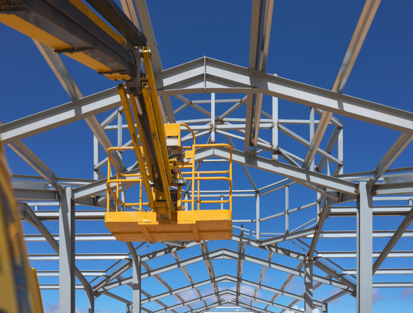
The economic fallout of these engineering disconnects surfaces immediately on the construction pad. A single dimensional misalignment during rafter-to-column field connection can idle a 100-ton hydraulic mobile crane at $350 per hour while delaying overall commissioning by weeks. Unplanned field torch cutting and magnetic drill hole enlargement void factory certifications and compromise structural integrity under AWS D1.1 mandates. Controlling fabrication geometry and erection cost requires mastering the principles in Prefab Steel Structure Warehouse Procurement: 7 Costly Pitfalls Overseas Buyers Must Avoid.
| Cost Driver | Initial Procurement Model (FOB) | Jobsite Erection Reality | Direct Financial Exposure |
|---|---|---|---|
| Primary Structural Framing | $1,250 per metric ton (GB Q355B base) | Section substitution violates AISC 360-16 L/240 deflection | Up to 35% tonnage increase during engineering rework |
| Surface Prep & Coating | Sa 2.0 commercial blast, 60 μm alkyd primer | Severe salt fog breakdown during 30-day ocean transit | Full field abrasive blast and recoat ($45–$65 per m²) |
| Foundation Integration | Assumed nominal baseplate centerlines | Pier coordinate variance exceeds AISC DG-1 ±3 mm limit | On-site hole slotting, thermal cutting, plate pack inserts |
| Structural Fasteners | Uncertified Grade 8.8 export bolts | Thread stripping and lack of verified pre-tension | 100% field bolt replacement with ASTM F3125 Grade A325 |
| Erection Rigging & Plant | Fixed 10-day mobilization window | Framing misalignment idles primary crane crews | $2,800 daily downtime per 100-ton mobile crane unit |
From the perspective of an EPC structural engineering director, overseas steel procurement cannot function as a transactional purchase order. It demands strict, non-negotiable quality safeguards addressing seven engineering failure categories:
- 1. Metallurgical chemistry deviations: Carbon equivalent values (CEV > 0.45) produce brittle heat-affected zones during welding.
- 2. Anchor bolt and baseplate tolerance collisions: Shop detailing fails to accommodate AISC 303-16 Section 7.5 erection clearances.
- 3. ISO container stowage envelope constraints: Irreversible lateral-torsional sweep during ocean transit occurs when member lengths push against container limits.
- 4. Marine corrosion and coating failure: Steel surfaces prepared below ISO 8501-1 Sa 2.5 profile standards fail to bond properly with 80 μm DFT epoxy zinc-rich primer, causing rapid rust during ocean transport.
- 5. Structural bolting grade drift: Field crews install non-compliant commercial bolts lacking tension control instead of specified structural assemblies.
- 6. Documentation fraud: Unverified Mill Test Reports (MTRs) missing verified heat traceability and independent chemical spectrometer verification.
- 7. Astronomical field remediation multipliers: A $20 CNC plasma detailing revision in the factory balloons into an uncontrolled $2,000 high-elevation field repair under commercial site labor rates.
Pitfall 1: Steel Grade Substitution & Metallurgy Mismatch (ASTM A572 Gr 50 vs. GB/T 1591 Q355B)
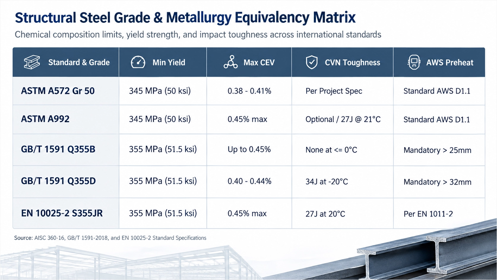
In international industrial projects, structural steel procurement frequently breaks down during the design translation phase. In the context of Prefab Steel Structure Warehouse Procurement: 7 Costly Pitfalls Overseas Buyers Must Avoid, unverified steel grade substitution represents the single largest hidden structural liability. Procurement teams often assume that ASTM A572 Grade 50 (or ASTM A992 for rolled wide-flange members) matches Chinese domestic GB/T 1591 Q355B on a 1:1 basis. Nominal yield strength equivalence (50 ksi / 345 MPa vs. 355 MPa) conceals dangerous disparities in carbon equivalent values and weldability.
The Metallurgy Behind Hydrogen-Induced Cracking
ASTM A992 restricts maximum carbon content to 0.23% while capping the chemical composition to control the Carbon Equivalent Value (CEV), ensuring dependable field weldability under AWS D1.1 without excessive preheating. In contrast, Chinese standard GB/T 1591-2018 permits Q355B ladle carbon content up to 0.20% (rising to 0.24% in actual product analyses for heavier plates) combined with manganese levels up to 1.60%.
The weldability of these plates is determined using the International Institute of Welding (IIW) carbon equivalent equation:
GB/T 1591 Q355B permits carbon equivalent values up to 0.45%, mandating preheat regimes under AWS D1.1 Table 3.2 that budget fabricators routinely omit. When primary structural columns or heavy crane runway girders use flange plates exceeding 25 mm (1.0 inch) in thickness, an elevated carbon and manganese chemistry pushes the actual heat CEV past 0.44%. Welding these components at ambient factory temperatures without a mandatory 65°C to 100°C (150°F to 212°F) preheat generates steep thermal quench cycles. The rapid cooling creates hard, brittle martensite in the Heat-Affected Zone (HAZ), leading to delayed hydrogen-induced underbead cracking (HIC) within 24 to 48 hours after joint completion.
Cold-Climate Impact Toughness Discrepancies
The second major failure point is notch toughness at low temperatures. Standard Q355B grade provides zero guaranteed Charpy V-Notch impact toughness at or below 0°C, risking catastrophic brittle fracture in cold-climate warehouse envelopes. GB/T 1591 mandates Charpy testing for Q355B only at a room temperature baseline of +20°C (minimum 34 J).
When structural framing is erected in regions subject to sub-freezing operating conditions, such as the Northern United States, Canada, or higher altitudes in Central Asia, local engineering codes enforce toughness thresholds of 27 J at -20°C or -30°C. If a low-cost manufacturer supplies standard Q355B, the primary portal frames enter service past their ductile-to-brittle transition curve. Under peak thermal contraction and design wind or snow gust loads, unnotched brittle failure can occur without yield deformation.
To satisfy international building codes, buyers must explicitly mandate GB/T 1591 Q355D (certified 34 J at -20°C) or Q355E (certified 34 J at -40°C) rather than generic Q355B.
Material Grade Comparison
Chemical and tensile property variances between Chinese GB steel and international structural grades dictate strict workshop protocols:
| Specification Attribute | ASTM A572 Gr 50 | ASTM A992 | GB/T 1591 Q355B | GB/T 1591 Q355D | EN 10025-2 S355J2 |
|---|---|---|---|---|---|
| Minimum Yield Strength (t ≤ 16 mm) | 345 MPa (50 ksi) | 345 MPa (50 ksi) | 355 MPa (51.5 ksi) | 355 MPa (51.5 ksi) | 355 MPa (51.5 ksi) |
| Tensile Strength Range | 450 – 620 MPa | 450 – 620 MPa | 470 – 630 MPa | 470 – 630 MPa | 470 – 630 MPa |
| Maximum Ladle Carbon (C) | 0.23% | 0.23% | 0.20% | 0.20% | 0.20% |
| Maximum Carbon Equivalent (CEV) | Optional | 0.45% max | 0.45% max | 0.45% max | 0.45% max |
| Charpy V-Notch Test Temperature | Supplemental | Supplemental | +20°C (+68°F) | -20°C (-4°F) | -20°C (-4°F) |
| Minimum CVN Absorbed Energy | Specified by PO | Specified by PO | 34 Joules | 34 Joules | 27 Joules |
| Welding Preheat Standard | AWS D1.1 Cat B | AWS D1.1 Cat B | AWS D1.1 / Table 3.2 | AWS D1.1 / Table 3.2 | EN 1090-2 Execution |
Mill Traceability Verification
Eliminating metallurgical mismatches requires contractually binding inspection procedures before steel hits the production floor:
Source plate steel directly from integrated mills with certified heat numbers, and reject unverified warehouse stock. Submit original EN 10204 Type 3.1 Mill Test Reports (MTRs) verifying ladle and product CEV under 0.42%. Enforce piece-mark traceability through shop fabrication, ensuring CNC plasma cutting meets ISO 9013 tolerances within ±0.5 mm, followed by ISO 8501-1 Sa 2.5 surface prep and 80 μm DFT epoxy zinc-rich primer application without obscuring heat stampings.
Pitfall 2: Anchor Bolt Pattern Misalignment and Baseplate Tolerance Collisions
The most immediate site-level crisis during warehouse erection occurs at the interface between the civil foundation and the structural steel column baseplate. Within the framework of Prefab Steel Structure Warehouse Procurement: 7 Costly Pitfalls Overseas Buyers Must Avoid, anchor rod misalignment represents the most frequent cause of day-one erection stoppages, disputed backcharges, and unauthorized field modifications.
The breakdown stems from an unmanaged conflict between fabrication tolerances and concrete placement practices. In our fabrication facility, multi-spindle CNC drilling lines process column baseplates to mechanical tolerances within ±0.5 mm. Similarly, AISC 303-16 (Code of Standard Practice for Steel Buildings and Bridges) Section 7.5 establishes strict tolerances for anchor rod placement, restricting variation to ±1/8 inch (3.2 mm) for center-to-center distances between individual rods in a group.
Local foundation contractors rarely achieve this level of precision. Cast-in-place concrete anchor rod placement routinely deviates by 12 mm to 25 mm, exceeding standard fabrication hole clearance tolerances by over 400%. When overseas fabricators provide standard bolt holes (rod diameter plus 1/16 inch or 2 mm per AISC 360-16 standard hole definitions), columns will not seat over the embedded foundation rods. Site crews are forced to halt crane operations, incurring equipment standby costs, or worse, use oxyacetylene torches to slot the baseplates on site. Uncontrolled field torching damages the base metal, violates AWS D1.1 structural welding protocols, and destroys the structural load-transfer path.
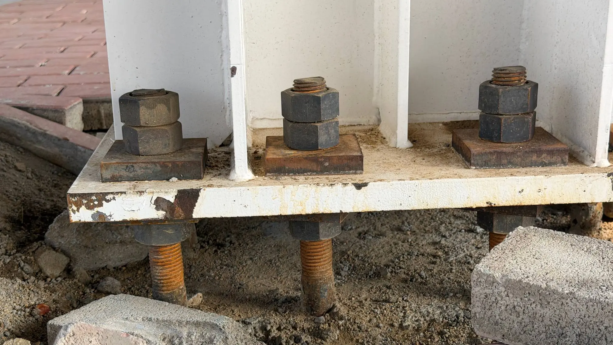
To prevent field clashing, procurement contracts must require the fabricator to detail baseplates according to AISC Design Guide 1 (Base Plate and Anchor Rod Design, Second Edition). AISC Design Guide 1 mandates oversized anchor rod holes (up to double the rod diameter) and thick plate washers to absorb concrete placement tolerances without field torch cutting. Oversized holes provide the necessary clearance for foundation drift, while heavy structural plate washers (minimum 3/8 inch to 1/2 inch thick ASTM A36 steel) span the enlarged opening and are subsequently fillet-welded over the baseplate after final plumb alignment.
| Anchor Rod Diameter (ASTM F1554) | Standard Clearance Hole Diameter | AISC Design Guide 1 Oversized Hole | Minimum Plate Washer Dimensions (ASTM A36) | Maximum Placement Drift Absorbed |
|---|---|---|---|---|
| 3/4 in (19 mm) | 13/16 in (21 mm) | 1-5/16 in (33 mm) | 2-1/2 × 2-1/2 × 3/8 in (65 × 65 × 10 mm) | ±1/4 in (±6.4 mm) |
| 1 in (25.4 mm) | 1-1/16 in (27 mm) | 1-13/16 in (46 mm) | 3-1/2 × 3-1/2 × 1/2 in (90 × 90 × 12 mm) | ±3/8 in (±9.5 mm) |
| 1-1/4 in (31.8 mm) | 1-5/16 in (33 mm) | 2-1/16 in (52 mm) | 4 × 4 × 1/2 in (100 × 100 × 12 mm) | ±1/2 in (±12.7 mm) |
| 1-1/2 in (38.1 mm) | 1-9/16 in (40 mm) | 2-5/16 in (59 mm) | 4-1/2 × 4-1/2 × 5/8 in (115 × 115 × 16 mm) | ±5/8 in (±15.9 mm) |
Engineering oversized baseplate holes solves only half the problem. Buyers must also mandate that the steel fabricator cut rigid 1:1 steel setting templates using CNC laser tables (fabricated from 3 mm to 4 mm structural sheet steel) with permanent centerlines and column orientation marks etched into the metal. Requiring the overseas fabricator to air-ship CNC steel bolt templates prior to the civil foundation pour eliminates 98% of baseplate-to-anchor alignment failures.
Dispatching these templates via air freight 4 to 6 weeks before structural shipping containers arrive forces the civil subcontractor to lock the anchor cage assemblies rigidly into place before and during the concrete pour. This workflow protects project schedules, controls erection costs, and ensures compliance with international structural codes.
Pitfall 3: Logistics Envelope Blindspots: Maritime Containerization & Rafter Splice Geometry
When managing international freight under Prefab Steel Structure Warehouse Procurement: 7 Costly Pitfalls Overseas Buyers Must Avoid, structural design cannot be separated from container boundary physics. A standard 40ft High Cube (40HC) ISO shipping container features internal dimensions of 11.98 m length, 2.340 m door width, and 2.585 m door opening height per ISO 1496-1. The strict internal length limit for structural members inside a 40ft High Cube container is 11.80 m, requiring rigid clear-span rafters to be sectioned into transportable modular segments. This 180 mm margin accommodates 50 mm end-wall dunnage, hardwood blocking, rigging tackle, and standard workshop fabrication length tolerances of ±2 mm per AWS D1.1.
Unqualified fabricators often divide portal rafters arbitrarily to fit maritime shipping containers, ignoring bending moment distributions. Splicing rafters at high-moment zones to improve container stowage increases bolt shear and prying forces by over 60% and requires expensive flange stiffeners.
In portal frames designed under AISC 360-16, maximum negative bending moments concentrate at the column-to-rafter haunch connection. The positive moment peaks near mid-span under gravity combinations (1.2D + 1.6L). Intermediate field splices must sit near points of contraflexure, typically between 15% and 22% of the clear span away from column centerlines, where bending moments approach zero.
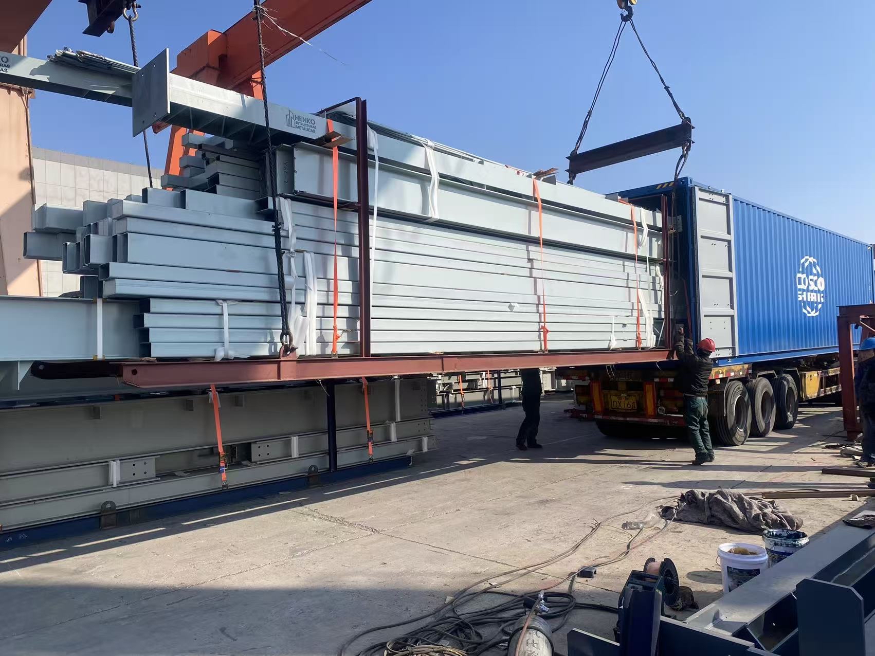
Moving a splice into a high-moment zone converts a simple shear-dominant connection into an extended end-plate moment connection governed by AISC Design Guide 16. This shift demands thicker end-plates (tp ≥ 25 mm to prevent prying yield mechanisms), full-penetration complete joint penetration (CJP) groove welds, and high-strength ASTM A490 or ISO Grade 10.9 structural bolts installed with calibrated direct tension indicators.
| Clear Span (m) | Transport Splice Count | Splice Coordinate From Eave (m) | Moment Ratio at Splice (Msplice / Mmax) | Connection Detailing Specification | Splice Weight Impact (kg/frame) |
|---|---|---|---|---|---|
| 24 m | 1 (Apex Splice) | 12.00 (Ridge) | 0.35 to 0.45 | 4-bolt unstiffened extended end-plate | Base Reference |
| 30 m | 2 (Haunch + Apex) | 3.80 / 15.00 | 0.12 to 0.18 | 8-bolt extended with exterior stiffeners | +140 kg |
| 36 m | 3 (Double Field) | 6.20 / 18.00 | 0.10 to 0.15 | 8-bolt extended flush per AISC DG 16 | +290 kg |
| 48 m | 4 (Modular Multi) | 7.50 / 16.50 | 0.08 to 0.14 | 12-bolt heavy moment end-plate | +520 kg |
Slender pre-engineered built-up web plates with slenderness ratios (h/tw) exceeding 150 require dedicated shipping stiffeners to avoid plastic deformation under dynamic ocean transit. Fabricated from Q355B or ASTM A572 Grade 50 plate, these thin-web sections face multi-axis dynamic loads during marine transport. Ocean vessels generate low-frequency cyclic accelerations up to 0.6g transverse roll and 0.4g vertical heave per IMO cargo securement guidelines.
Without temporary L50×50×4 angle bracing welded across unstiffened webs or timber compression chocks strapped between stacked rafter bundles, slender web plates experience local out-of-plane lateral warping and oil-canning deformation. These distortions ruin the tight ±0.5 mm CNC flange-to-web squareness tolerances required for field alignment. Remediating warped webs on-site damages the Sa 2.5 blast-cleaned surface and compromises the 80-micrometer dry film thickness (DFT) epoxy zinc-rich primer system, leaving the structural steel open to long-term corrosion.
A Smaller Ask
If you are currently evaluating framing schemes or bay spacing configurations for an upcoming facility, share your design criteria with our technical department. Operating from a 60,000 sqm facility, our automated CNC cutting lines maintain sub-millimeter tolerances compliant with AISC 360, AWS D1.1, and EN 1090 standards. Review our structural detailing capabilities and load-bearing framing profiles for your upcoming project.
Pitfall 4: Deficient Surface Preparation & Coating Failures in Aggressive Marine Transit
In the analysis of Prefab Steel Structure Warehouse Procurement: 7 Costly Pitfalls Overseas Buyers Must Avoid, marine transit degradation represents the most severe physical and electrochemical risk to structural steelwork before jobsite delivery. Structural shipments from Asian manufacturing yards to destinations across the Middle East, the Americas, Europe, or Africa spend between 30 and 60 days inside ocean vessel holds or lashed to open flat racks traversing equatorial shipping lanes.
During transit, cargo hold temperatures fluctuate violently between 10°C and 50°C every 24 hours. Combined with relative humidity values consistently exceeding 90%, these temperature differentials trigger heavy cyclic condensation, commonly known as cargo sweat. Droplets saturated with airborne chlorides saturate steel surfaces, turning stagnant moisture into an aggressive electrolyte that accelerates oxidation across every exposed square millimeter.
Low-tier fabricators minimize production expenses by bypassing proper mechanical shot blasting, opting instead for manual wire-brushing to ISO 8501-1 St 2. Single-coat shop alkyd primers under 40 μm fail within 14 days of maritime exposure, arriving at destination ports with pervasive rust and delamination.
Applying high-grade protective paint over unblasted mill scale triggers galvanic micro-cells that cause full coating debonding within 12 months of erection. Mill scale (iron oxide, Fe3O4) is electrochemically noble compared to carbon steel base metal (Fe). When moisture penetrates microscopic defects in an alkyd or thin primer film, an active galvanic cell forms: the steel acts as an anode and corrodes rapidly beneath the scale, producing voluminous rust bloom rated at ISO 4628-3 Ri 4 or Ri 5 by the time the vessel discharges.
| Surface Preparation Standard | Coating Build Architecture | Nominal Total DFT (μm) | 45-Day Ocean Transit Performance | Fabricator Cost Impact ($/m²) |
|---|---|---|---|---|
| ISO 8501-1 St 2 (Manual Wire Brush) | 1× Single-Coat Alkyd Primer | 30 – 40 μm | Severe Ri 4/Ri 5 rust bloom, peeling | Baseline ($0.00) |
| ISO 8501-1 Sa 2.0 (Commercial Blast) | 1× Epoxy Primer + 1× Alkyd Enamel | 90 – 110 μm | Early pinpoint corrosion, undercutting | +$3.50 |
| ISO 8501-1 Sa 2.5 / SSPC-SP 10 | 1× Zinc-Rich Epoxy + 1× Epoxy MIO + 1× PU | 225 – 275 μm | Zero corrosion (Ri 0), fully intact | +$12.80 |
| ISO 8501-1 Sa 3.0 / SSPC-SP 5 | Thermal Spray Aluminum (TSA) + Sealer | 250 – 320 μm | Total protection against direct salt wash | +$29.00 |
To prevent cargo rejection at the port of discharge, procurement contracts must enforce centrifugal abrasive blast cleaning to ISO 8501-1 Sa 2.5 / SSPC-SP 10 (Near-White Metal). Steel grit and shot blends must yield a sharp angular anchor profile of 50 to 75 μm, verified per ASTM D4417 Method B, providing the mechanical interlock required for chemical coatings.
Specifying an ISO 12944-5 C4/C5 compliant system with a zinc-rich epoxy primer (≥80% zinc dust) provides sacrificial galvanic protection that survives extended transoceanic shipping. The full structural warehouse coating schedule must specify:
- 1. Primer Coat: 75 μm dry film thickness (DFT) zinc-rich epoxy primer formulated with at least 80% metallic zinc dust by weight in the dry film, per SSPC-Paint 20 Type II.
- 2. Intermediate Barrier Coat: 100 to 125 μm DFT epoxy micaceous iron oxide (MIO), creating a dense platelet matrix that blocks moisture and chloride ingress.
- 3. Finish Topcoat: 50 to 75 μm DFT aliphatic acrylic polyurethane, protecting against chalking, ultraviolet radiation, and mechanical abrasions incurred during heavy dunnage banding.
Enforce mandatory third-party inspection sign-offs requiring SSPC-PA 2 dry film thickness inspection records. The 80/20 rule must be strictly applied across all column flanges, rafter webs, and connection plates: no individual spot measurement may fall below 80% of specified nominal DFT, and the average of each 10 m² section must meet or exceed 100% of target thickness prior to container loading.
Pitfall 5: Structural Bolting Ambiguities: Grade Drift, Pre-tensioning & Slip-Critical Flaws
A critical failure point identified in Prefab Steel Structure Warehouse Procurement: 7 Costly Pitfalls Overseas Buyers Must Avoid is the misapplication and unverified substitution of structural fastening hardware. Procurement documents frequently request high-strength assemblies without delineating the mechanical and metallurgical differences between North American specifications (ASTM F3125 Grade A325 and A490) and international metric conventions (ISO 898-1 Property Classes 8.8 and 10.9). This ambiguity causes grade drift.
Uncertified overseas metric Property Class 8.8 bolts sourced without third-party heat verification frequently fail tensile yield and hydrogen embrittlement criteria. Low-tier hardware suppliers often deliver quench-and-tempered carbon steels lacking documented boron limitations or trace element controls. When structural joints undergo rotational capacity (ROCAP) testing per ASTM F3125 Annex A2, substandard assemblies strip threads, crack at the thread-to-shank transition, or exhibit thread galling long before achieving the required pre-tension force.
ASTM F3125 (A325/A490) requires mandatory Annex A2 ROCAP testing, lot traceability, and strict geometry (heavy hex). Standard ISO 898-1 (8.8/10.9) fasteners from commodity brokers often lack ductility controls, certified heat treat batch records, and matched hardened washers (ASTM F436).
Beyond bolt metallurgy, the interface friction of connected plies determines joint stability. Engineers categorize high-strength bolted connections into bearing-type and slip-critical joints according to the Research Council on Structural Connections (RCSC) Specification for Structural Joints Using High-Strength Bolts. Bearing connections permit minor slip until the bolt shank bears directly against the hole wall. In contrast, slip-critical connections rely strictly on clamping force and surface friction to prevent any relative movement between plies under service and seismic loads.
Allowing fabricators to paint faying surfaces with standard high-gloss epoxy drops friction slip coefficients from Class A (μ = 0.30) to μ < 0.15, inducing premature joint slippage. Slick structural primers act as lubricants inside the connection. If primary moment connections slip into bearing prematurely, the frame undergoes unintended lateral drift, misaligning crane runways and cracking secondary wall envelopes.
| Bolt Specification | Property Class / Grade | Min Tensile (MPa) | Proof Load (MPa) | Faying Surface Condition | Slip Coeff (μ) | Primary Application |
|---|---|---|---|---|---|---|
| ASTM F3125 / F3125M | Grade A325 / A325M | 830 MPa | 600 MPa | Clean Mill Scale (Class A) | 0.30 | Secondary Bracing / Purlins |
| ASTM F3125 / F3125M | Grade A490 / A490M | 1040 MPa | 830 MPa | Blast-Cleaned Sa 2.5 (Class B) | 0.50 | Moment Frames / Splices |
| ISO 898-1 / EN 14399-3 | Property Class 8.8 HR | 800 MPa | 580 MPa | Unpainted Blasted Steel | 0.45 | Portal Frame Splices |
| ISO 898-1 / EN 14399-4 | Property Class 10.9 HV | 1000 MPa | 830 MPa | Ethyl Silicate Zinc (Approved) | 0.50 | Heavy Industrial Columns |
| Non-Compliant Comm. | Class 8.8 (Painted) | Variable (<800) | Unverified | High-Gloss Epoxy Coating | < 0.15 | Non-Structural Ancillaries |
To preserve joint integrity, project specifications must prohibit standard paint within the bolt pattern envelope plus a 25 mm perimeter. The steel within this zone must either remain unpainted blast-cleaned steel meeting SSPC-SP 10 (Sa 2.5) to achieve a Class B surface (μ = 0.50), or receive an approved, certified inorganic ethyl silicate zinc-rich primer with documented friction test reports per RCSC Appendix A.
Field execution requires strict pre-tensioning verification. Snug-tight conditions are insufficient for cyclic wind or seismic zones. RCSC structural specifications mandate verified slip-critical connections for all moment-frame rafter splices, inspected via Direct Tension Indicators or Turn-of-Nut verification.
When deploying Direct Tension Indicators (DTIs per ASTM F959), erection crews must verify gap refusal using feeler gauges to ensure minimum design clamping tension. If using the Turn-of-Nut method, field quality control must enforce preliminary match-marking of the nut and bolt point prior to applying the specified partial turn (typically one-third to two-thirds turn, depending on bolt length-to-diameter ratios per RCSC Table 8.2). Reject any overseas structural package that lacks fastener MTRs (including ASTM F436 washers) or documented faying-surface blast profiles before field erection begins.
Pitfall 6: Documentation Fraud: Unverified MTRs and Omission of Factory Trial Pre-Assembly
In the context of Prefab Steel Structure Warehouse Procurement: 7 Costly Pitfalls Overseas Buyers Must Avoid, the most catastrophic project failures originate not from structural design software errors, but from fraudulent documentation and unverified shop geometry. Up to 20% of unverified MTRs in low-tier international supply chains fail physical heat-number plate cross-referencing, disguising high-sulfur scrap-rerolled plate. Low-tier fabricators frequently provide photocopied, illegible, or generic mill certificates that do not correspond to the actual steel plates feeding their CNC plasma cutting tables. High-sulfur, scrap-derived plates exhibit severe micro-segregation, poor z-axis ductility, and extreme vulnerability to lamellar tearing under the heavy shrinkage stresses of Complete Joint Penetration (CJP) welding.
Mandating EN 10204 Type 3.1 inspection certification legally binds the manufacturer's independent QA department to verify chemical and mechanical test compliance. Unlike Type 2.2 certificates, which only assert generic compliance based on non-specific shop testing, a genuine 3.1 certificate validates specific yield strength, tensile elongation, Charpy V-notch impact values (such as 27 Joules at zero degrees Celsius for Q355C or ASTM A992), and maximum Carbon Equivalent Values (CEV under 0.44 per AWS D1.1). Factory inspectors must cross-reference the heat numbers hard-stamped directly into the steel plates and hot-rolled profiles against the corresponding laboratory chemical analysis sheets before any cutting begins.
| Inspection Scope | Joint or Element Type | Governing Standard | Sampling Rate | Field Rejection Risk Avoided |
|---|---|---|---|---|
| Material Verification | Base plates and girder plates | EN 10204 3.1 / ASTM A6 | 100% heat numbers | Lamellar tearing, brittle fracture, high sulfur inclusion |
| Visual Testing (VT) | All shop fillet and groove welds | AWS D1.1 Clause 6.9 | 100% production | Undercut deeper than 0.5 mm, porosity, lack of fusion |
| Ultrasonic Testing (UT) | Rafter-to-column CJP moment welds | ISO 17640 / AWS D1.1 Cl 6 | 20% to 100% CJP | Sub-surface planar defects, root cracking, slag inclusion |
| Magnetic Particle (MT) | Crane brackets, heavy fillets over 10 mm | ASTM E709 / AWS D1.1 Cl 6 | 10% critical welds | Heat-affected zone (HAZ) micro-cracks, surface tears |
| Trial Pre-Assembly | Primary portal frame and purlin bay | AISC 303-16 / EN 1090-2 | 1 bay per 5,000 sqm | Bolt hole clashing, camber loss, field reaming delays |
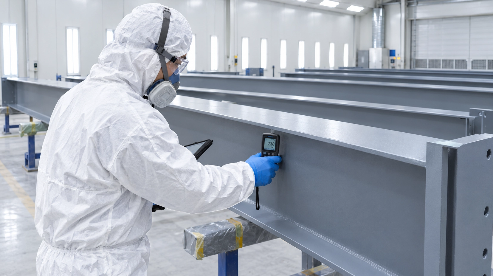
Relying purely on documentation without non-destructive testing (NDT) hold points leaves structural integrity to chance. Your fabrication contract must enforce a rigid NDT regime: 100% Visual Testing (VT per AWS D1.1), minimum 20% Ultrasonic Testing (UT per ISO 17640 / AWS D1.1 Clause 6) on all CJP column-to-base plate and beam-to-column moment splices, and Magnetic Particle Testing (MT per ASTM E709) across heavy fillet welds subject to fatigue.
The final barrier against offshore disaster is physical dry assembly. Factory trial pre-assembly of at least one primary frame bay detects 100% of camber discrepancies, bolt hole clashing, and sweep deviations before export crating. A complete trial consists of laying out two primary columns, fully splicing rafter segments, and installing eave struts and purlins under workshop cranes. Permissible fabrication tolerances, such as flange out-of-squareness within 3 mm and bolt-hole center-to-center distances within 1.5 mm, stack up across a 36-meter clear span. If physical trial erection is restricted by yard space, require high-definition 3D terrestrial laser scanning. Comparing the captured point-cloud data against the Tekla Structures fabrication model guarantees that every pre-drilled connection aligns perfectly before components are sealed inside shipping containers.
Pitfall 7: The 1:10:100 Cost Multiplier: Shop vs. Field Remediation Economics
In the reality of international structural contracting, geometric and dimensional errors do not scale linearly; they compound exponentially. When analyzing Prefab Steel Structure Warehouse Procurement: 7 Costly Pitfalls Overseas Buyers Must Avoid, the mathematical reality of field remediation represents the single greatest threat to project contingency funds. The 1:10:100 fabrication rule demonstrates that a minor $150 shop hole misalignment escalates to a minimum $1,500 field rectification and upwards of $15,000 in liquidated delay penalties. An error caught at the CNC drill line requires fifteen minutes of shop technician labor to plug-weld, grind flush, and redrill. That exact same mismatch discovered sixty feet in the air halts an entire erection sequence, stranding heavy lifting machinery and ironworker crews.
Jobsite remediation immediately incurs direct and indirect surcharges. A 100-ton hydraulic mobile crane standing idle while an overseas rafter connection is flame-straightened costs $2,500 to $3,500 per day in standby charges, with standard equipment rental agreements billing between $250 and $400 per hour whether the hook works or sits idle. Field welding modifications on heavy structural sections require preheating, certified mobile AWS welders, and third-party NDT reinspection, multiplying labor costs by a factor of 8× compared to controlled indoor shop fabrication rates.
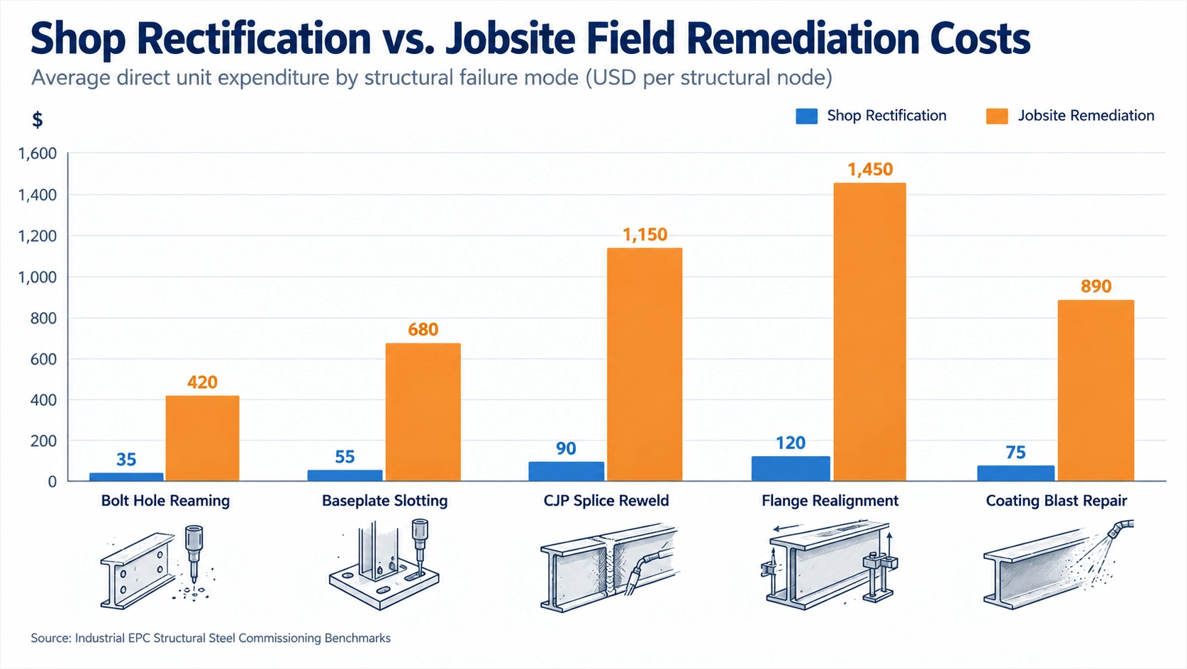
Modifying ASTM A992 wide-flange beams or Q355B built-up plate girders at height demands severe procedural overhead under AWS D1.1 (Structural Welding Code: Steel). Erection crews cannot simply run flux-cored wire over an out-of-square joint. The remediation requires:
- • Certified mobile diesel welding rigs billing at $120 to $180 per hour per welder.
- • Flange thicknesses exceeding 38 mm must be preheated to 150°F to 225°F using ceramic heating pads or oxy-propane rosebud torches per AWS D1.1 Table 3.3.
- • Deploying heavy-duty magnetic base drills to slot or ream holes larger, requiring replacement hardened ASTM F436 washers or engineering approval for oversized holes under AISC 360-16 Table J3.3.
- • Air carbon arc gouging defective shop welds, grinding the root to bright metal, and running multi-pass field welds in restricted overhead (4G) or vertical (3G) positions.
- • Retaining a certified third-party Level II technician to execute magnetic particle testing (MT) per ASTM E709 or ultrasonic testing (UT) per ASTM E164.
- • Manually cleaning the heat-affected zone to SSPC-SP 11 (Power Tool Cleaning to Bare Metal) and applying high-solids zinc-rich primer to re-establish an 80 μm nominal dry film thickness (DFT).
Table 2: Empirical Cost Comparison Matrix: Factory Shop vs. Field Jobsite Remediation
| Defect Classification | Workshop Rectification Scope | Shop Cost (USD) | Field Jobsite Remediation Scope | Field Cost (USD) | Cost Multiplier |
|---|---|---|---|---|---|
| Slotted Hole Misalignment (4–8 mm offset) | CNC drill repositioning or automated plug weld and redrill prior to blast | $45 – $75 | Magnetic base drill field reaming, structural washer plate installation, bolt retorque | $650 – $1,100 | 14× – 15× |
| Rafter Camber Deviation (> L/500 out of tol.) | Mechanical cold straightening in 500-ton hydraulic shop press bed | $180 – $260 | Line heating and flame-straightening at height, crane holding line, shoring tower | $2,800 – $4,200 | 15× – 16× |
| Flange Gouge or Notch (> 5 mm depth) | Submerged arc weld repair, mechanical grinding flush, in-house MT check | $60 – $110 | Mobile preheat rig, AWS D1.1 3G/4G SMAW weld, mobile third-party MT inspection | $850 – $1,450 | 13× – 14× |
| Coating Damage / Blistering (> 200 μm run) | Localized grit blast to Sa 2.5, automated airless spray to target DFT | $30 – $55 | Hand tool scraping to St 3, brush-applied two-pack epoxy mastic and PU topcoat | $400 – $700 | 12× – 13× |
Shandong XinQiao mitigates these field liabilities through full 3D spatial laser scanning and physical pre-assembly shop trial fitting of primary portal frames, rigid haunch splices, and heavy crane runway brackets prior to container stuffing, guaranteeing bolt-hole alignment tolerances within ±1.0 mm before structural members leave the plant.
Clear-Span Engineering & Cost Optimization Matrix (AISC vs. MBMA Guidelines)
In our project engineering reviews at Shandong XinQiao Steel Structure Co., Ltd., overseas clients frequently request maximum interior clear spans without accounting for the non-linear cost curves governing structural steel design. Within our technical field review, "Prefab Steel Structure Warehouse Procurement: 7 Costly Pitfalls Overseas Buyers Must Avoid", unoptimized clear-span specification ranks among the primary drivers of budget overruns. Structural clear-span portal frames are governed by first-order and second-order bending moments calculated by the equation:
Because maximum moment scales quadratically with span length (L), doubling clear span from 24 m to 48 m increases main portal frame bending moments by 300% (M = wL2/8), requiring heavier plate haunches and deeper foundations to resist massive overturning moments.
Conventional clear-span portal frames reach their primary economic inflection point at 45 m; spans beyond 60 m increase steel framing weight exponentially toward 95 kg/m². Standard pre-engineered buildings (PEB) use tapered solid-web portal frames efficiently between 30 m and 45 m (100 ft to 150 ft). Spans between 48 m and 60 m demand web depths exceeding 1,200 mm at column-rafter knee haunches, alongside thick flange plates (often 25 mm to 32 mm Q355B or ASTM A572 Grade 50) that strain standard automated submerged arc welding lines. Spans exceeding 60 m (200 ft) economically transition out of rigid-frame plate girders into open-web steel trusses or three-dimensional space frames to avoid prohibitive dead-load penalties.
Table 3: Clear-Span Width vs. Material Consumption and Baseline Metrics
| Span Width (m) | Structural Framing Topology | Haunch Web Depth (mm) | Primary Steel Density (kg/m²) | Fab Cost Baseline ($/m²) | Overturning Moment at Base (kN·m) |
|---|---|---|---|---|---|
| 20 m (65 ft) | Tapered Portal Frame | 550 – 700 mm | 28 – 35 kg/m² | $32 – $42 | 180 – 260 kN·m |
| 30 m (100 ft) | Tapered Portal Frame | 800 – 950 mm | 38 – 48 kg/m² | $45 – $58 | 390 – 540 kN·m |
| 45 m (150 ft) | Heavy Built-up Portal | 1,100 – 1,300 mm | 55 – 70 kg/m² | $68 – $88 | 850 – 1,150 kN·m |
| 60 m (200 ft) | Heavy Plate / Haunched | 1,400 – 1,700 mm | 75 – 95 kg/m² | $95 – $125 | 1,800 – 2,400 kN·m |
| > 60 m (> 200 ft) | Tubular Open-Web Truss | 2,200 – 3,500 mm | 60 – 78 kg/m² | $82 – $110 | 1,100 – 1,600 kN·m |
Serviceability Limit States (IBC, AISC, and AISI S100)
Structural integrity demands compliance with serviceability criteria dictated by the International Building Code (IBC) and AISC 360-16:
- • Roof Deflection Limits: Under IBC Chapter 16 and AISC Design Guide 3, roof rafters supporting standing seam metal roofs must not exceed a live load deflection of L/180, or L/240 when supporting plaster ceilings or direct-applied finishes.
- • Lateral Drift Limits: Main wind force resisting frames (MWFRS) must restrict column drift to between H/100 and H/200 under 10-year mean recurrence interval (MRI) wind loads, preventing exterior cladding panel disengagement.
- • Cold-Formed Secondary Members: Cold-formed Z-purlins designed to AISI S100-16 must be verified for distortional, local, and lateral-torsional buckling under combined gravity and wind-uplift load combinations.
Engineering Optimization Protocols
To maintain budgetary discipline without sacrificing usable floor operations, our design office applies four structural adjustments:
- 1. Bay Spacing Calibration: Widening primary bay spacing from 6.0 m to 8.5 m combined with continuous cold-formed Z-purlin lap splices reduces total structural steel building weight by 8% to 12%. Fewer portal frames mean fewer fabricated assemblies, fewer foundation piers, and reduced field-crane hours.
- 2. Web Taper Profiling: Rafter webs are cut along an automated CNC profile (tolerances within ±0.5 mm), concentrating material depth strictly at regions of high bending moment (knee haunches and peak joints) while slimming mid-span sections.
- 3. Continuous Purlin Laps: Specifying nested Z-purlin overlaps extending 10% to 15% past the rafter centerline provides negative moment continuity, allowing thinner gauge steel (e.g., down from 2.5 mm to 2.0 mm) to span 8 m to 9 m bays safely.
- 4. Intermediate Gravity Posts: When logistics permit a central forklift transit lane, introducing central pipe columns (ASTM A500 Grade B HSS) splits a 48 m clear span into two 24 m spans. This cuts rafter bending moments by up to 75%, lowering steel framing consumption back down to roughly 35 kg/m².
Fabricated components receive Sa 2.5 shot-blast preparation (ISO 8501-1) with 80 μm DFT epoxy zinc-rich priming before shipment, matching structural design with factory-grade corrosion protection. Anchor bolt layouts must be maintained within ±3 mm per AISC 303-16 to ensure exact load transfer into the substructure.
Overseas Structural Steel QA/QC Procurement Protocol & Verification Matrix
In managing structural steel supply contracts for international industrial facilities, systematic shop-floor governance supersedes post-delivery claims. As outlined in our field operations guide, Prefab Steel Structure Warehouse Procurement: 7 Costly Pitfalls Overseas Buyers Must Avoid, structural defects discovered after container discharge in export destinations create severe schedule delays and disproportionate back-charge liabilities. Once steel packages are packed into shipping containers, field modifications at the jobsite cost ten times more than shop corrections.
Overseas steel supply contracts must condition a minimum 25% progress payment milestone upon third-party engineering inspection sign-off prior to container loading. Payment retention is the primary risk mitigation tool. Withholding a 20% to 30% milestone payment until an accredited international inspection agency, such as SGS, Bureau Veritas, or TÜV Rheinland, issues an unqualified Inspection Release Note (IRN) guarantees manufacturer compliance before bill of lading issuance.
Independent third-party NDT inspection at 20% steel cutting and 80% fabrication completion eliminates over 95% of cross-border dimensional and welding defects. A five-phase quality assurance protocol must be integrated into the purchase contract purchase order terms:
- 1. Phase 1: Mill Ingestion & Raw Material Qualification: Fabricators must cross-reference 100% of incoming steel plates and wide-flange beams with heat-stamped Mill Test Reports (MTRs) tracing to ASTM A992, ASTM A572 Grade 50, or EN 10025-2 S355JR/J2. Independent laboratory testing must verify carbon equivalence (CEV under 0.45%) via optical emission spectrometry (OES) wet spark analysis, alongside Charpy V-Notch (CVN) impact tests confirming energy absorption of at least 27 Joules at -20 degrees Celsius.
- 2. Phase 2: Fit-Up & Tack Welds: Component fit-up for primary portal frame rafters, crane girders, and built-up H-sections must adhere strictly to AWS D1.1 Table 5.1. Inspectors must check root openings (±1.5 mm), bevel prep angles (±5 degrees), and web-to-flange alignment offsets prior to welding arc initiation.
- 3. Phase 3: Post-Weld Non-Destructive Testing (NDT) Hold Points: Welds require 100% Visual Testing (VT) per AWS D1.1 Clause 6 criteria. Complete Joint Penetration (CJP) groove welds at beam-to-column connections and crane rail splices demand a minimum 20% Ultrasonic Testing (UT) sample, scaling to 100% on high-fatigue crane runway girders. Fillet welds on shear lugs, crane corbels, and stiffener plates require 100% Magnetic Particle Testing (MT) to detect root cracks.
- 4. Phase 4: Factory Pre-Assembly & Geometric Dimensional Inspection: AISC 303 Section 6 dimensional tolerance compliance must be certified using 3D total stations before structural members enter the blast cleaning and painting booth. Shop fabricators must execute trial shop assemblies of complex portal frame splices and multi-span truss configurations. Technicians check rafter sweep, mid-span camber, column plumb (within 1:1000 or ±3 mm), and CNC hole centers (±1.0 mm tolerance per hole group).
- 5. Phase 5: Surface Preparation, Protective Coating & Ocean Packing: Steel components require centrifugal wheel abrasive blasting to ISO 8501-1 Sa 2.5 (SSPC-SP 10), establishing an angular anchor profile of 40 to 75 microns. Dry film thickness (DFT) must be verified per SSPC-PA 2 via calibrated magnetic gauges. For maritime shipping, members require vapor corrosion inhibitor (VCI) shrink wrap, desiccant bags within sealed bundles, soft-edge corner protectors, and treated softwood timber dunnage to prevent transport impact distortion.
Table 4: Structural Steel Shop Fabrication QA/QC Verification Matrix
| Production Stage | Quality Parameter & Inspection Scope | Governing Standard | Sampling & Acceptance Criteria | Quality Hold Point & Release Sign-Off |
|---|---|---|---|---|
| Phase 1: Material Ingestion | Chemical composition, tensile yield, Charpy CVN (-20°C) | ASTM A6 / EN 10204 3.1 | 100% heat match; 1 OES test per 20 tonnes; CVN ≥ 27 J | Hold Point 1: Raw Material Release for Cutting |
| Phase 2: Joint Fit-Up | Root face, gap, groove angle, alignment offset | AWS D1.1 Table 5.1 | Root gap ±1.5 mm; bevel ±5°; offset < 2.0 mm | Hold Point 2: Fit-Up Sign-Off Prior to Welding |
| Phase 3: Welding NDT | Subsurface defects, porosity, incomplete fusion, undercut | AWS D1.1 / ISO 17640 | 100% VT; 20% to 100% UT on CJP; 100% MT on shear lugs | Hold Point 3: NDT Clearance Certificate |
| Phase 4: Pre-Assembly | Camber, sweep, bolt gauge, rafter pitch, frame plumb | AISC 303 Section 6 | 10% trial fit; hole centers ±1.0 mm; camber ±3 mm | Hold Point 4: Dimensional Release to Surface Prep |
| Phase 5A: Surface Prep | Blast cleanliness, surface roughness, salt residue | ISO 8501-1 / SSPC-SP 10 | Sa 2.5 profile; depth 40–75 μm; salts < 35 mg/m² | Hold Point 5: Blast Profile Sign-Off |
| Phase 5B: Coating | Primer DFT, intercoat adhesion, final dry thickness | SSPC-PA 2 / ISO 12944 | 5 spots per 100 sq ft; zero curing blisters; cross-hatch 4B | Hold Point 6: Coating Inspection Certificate |
| Phase 5C: Stuffing | Container dunnage, VCI wrapping, chain lashing tension | CTU Code / IMO CSS Code | 100% visual; timber dunnage isolation; zero steel-on-steel | Final Hold: Inspection Release Note (IRN) for BL |
Frequently Asked Questions: Navigating Overseas Prefab Steel Warehouse Sourcing
Navigating international supply chains for pre-engineered structural steel requires strict adherence to international building codes, precision fabrication tolerances, and validated material certifications. To prevent severe project delays and structural rejections, engineering directors and procurement managers must understand how design choices impact material economics, compliance pathways, and ocean transport logistics. The following engineering evaluations address the technical friction points documented in our field guide.
What is the maximum clear span for a pre-engineered steel warehouse?
Solid-web rigid portal frames fabricated to AISC 360-16 specifications reach an economic upper threshold between 36 meters (118 feet) and 45 meters (148 feet). While spans exceeding 60 meters are technically feasible using continuous built-up plate girders, the structural efficiency drops sharply past 36 meters.
Beyond a 36-meter clear span, rafter haunch depths frequently exceed 1,100 millimeters to satisfy serviceability deflection limits (typically L/180 for roof snow loads or L/240 for total load per IBC Table 1604.3). To prevent local web buckling under heavy negative bending moments at the knee joint, designers must specify web thicknesses of 14 to 20 millimeters along with closely spaced transverse stiffeners detailed to AISC 360-16 Section G2. These large web depths create volumetric inefficiencies inside standard shipping containers, driving up sea freight rates because deep members consume cubic container volume before reaching payload weight limits. When internal operational requirements allow intermediate supports, substituting a 48-meter clear span with a multi-span frame (such as two 24-meter bays with interior pipe or H-columns) reduces structural steel tonnage by 25% to 35%. For uninterrupted clear spans greater than 45 meters, switching from solid-web portal frames to open-web structural steel trusses delivers a significantly higher strength-to-weight ratio.
| Clear Span (m) | Structural Framing Typology | Primary Steel (kg/m²) | Haunch Depth (mm) | Footing Volume (m³) | Average FOB Cost ($/m²) |
|---|---|---|---|---|---|
| 24 m | Solid-Web Portal Frame | 28 – 34 | 650 – 750 | 4.2 m³ | $48 – $56 |
| 30 m | Solid-Web Portal Frame | 35 – 42 | 800 – 950 | 6.5 m³ | $58 – $68 |
| 36 m | Solid-Web Portal Frame | 44 – 52 | 1000 – 1150 | 9.8 m³ | $72 – $84 |
| 42 m | Built-Up Tapered Frame | 55 – 68 | 1250 – 1400 | 14.2 m³ | $90 – $110 |
| 48 m | Open-Web Truss System | 48 – 58 | 1800 – 2200 | 8.6 m³ | $85 – $102 |
How does clear-span width affect steel tonnage and building cost?
Primary steel consumption follows a non-linear growth curve as clear-span dimensions expand. As span length doubles from 24 meters to 48 meters in a single-span rigid portal frame, the bending moment at the haunches quadruples under uniform gravity loading [M = (w · L2) / 8]. To resist this moment, structural engineers must increase the cross-sectional area of both column flanges and rafter chords, compounding base tonnage.
This dimensional increase directly impacts foundation substructure design. Clear spans exceeding 36 m generate massive haunch reactions that expand concrete spread footing volumes by 35% to 50% compared to buildings with interior support columns. The lateral thrust and overturning moments delivered to the column bases under design wind speeds (ASCE 7-16/7-22 combinations) produce severe uplift forces. In pinned-base models, the extreme shear transfers demand heavy anchor bolt clusters and expanded footing footprints to prevent overturning. In fixed-base models designed per AISC Design Guide 1 Section 2.3, the moment transferred directly into the reinforced concrete necessitates deep, heavily reinforced foundation blocks to satisfy ACI 318-19 soil-bearing limits, which increases civil excavation and concrete placement expenses on site.
What are the main structural limits of clear span prefab warehouses?
The primary limits of wide clear-span buildings center on lateral drift, connection fatigue, foundation reactions, and foreign steel equivalence verification. Under high lateral wind or seismic events, wide portal frames develop substantial lateral sway at the eave. Controlling this deflection to code thresholds (H/60 to H/100 for open warehouse envelopes, or H/200 when supporting perimeter masonry or precast panels) requires heavier column sections than required for gravity load resistance alone.
Material substitution across jurisdictions presents another strict limit. IBC Section 2205 permits international steel grade equivalence provided an Engineer of Record (EOR) submits certified EN 10204 Type 3.1 test reports validating ASTM A6 chemistry and tensile criteria. When using Chinese standard GB/T 1591 Q355B in place of ASTM A572 Grade 50 or ASTM A992, the fabricator must supply independent chemical heat analyses and mechanical pull tests confirming minimum yield strength (Fy ≥ 355 MPa), ultimate tensile strength (470–630 MPa), elongation percentages (≥ 21%), and carbon equivalent values (CEV ≤ 0.44%). For structures erected in seismic design categories C through F, Charpy V-notch (CVN) impact testing must verify minimum energy absorption of 27 Joules at 0°C or -20°C per AISC 341-16.
Securing local municipal permits requires quality verification. Building permit authorities require certified AWS D1.1/CWI welding inspection records, fabricator quality management certifications (ISO 3834 / AISC), and stamped structural calculations for import approval. These calculation packages must include finite element analysis run under local loading codes, anchor bolt placement drawings detailed to ±3 mm tolerances, and Non-Destructive Testing (NDT) logs including 100% Visual Testing (VT) and minimum 20% Ultrasonic Testing (UT) on all Complete Joint Penetration (CJP) groove welds at moment frames.
How can tonnage and cost be optimized in large clear-span designs?
Optimizing costs on large overseas steel orders requires integrating manufacturing parameters into the initial structural engineering phase:
- 1. Modulate Frame Geometry: Introduce intermediate gravity columns where process flows permit. Transitioning an open 42-meter warehouse into a two-bay 21-meter framing system reduces total framing steel weight by approximately 30% while simplifying base plate details and foundation concrete needs.
- 2. Refine Built-Up Plate Profiles: Exploit automated submerged-arc welding (SAW) lines by detailing tapered, non-prismatic rafters and columns. By varying the web plate depth and flange thickness strictly in accordance with the moment envelope, the engineer cuts unnecessary steel weight from low-stress zones near the frame inflection points. CNC plasma cutting must maintain tolerances within ±0.5 mm to ensure proper fit-up during pre-assembly.
- 3. Cold-Formed Secondary Optimization: Use continuous, overlapping Z-shaped purlins and girts rolled from ASTM A653 Grade 50 (or Grade 55) high-strength galvanized steel with minimum G90 (Z275) zinc coatings instead of simple-span C-channels. Continuous lap detailing over intermediate rafters reduces secondary structural steel volume by 15% to 20%.
- 4. Standardize Marine Transport Packaging: Rafter segments should be detailed with intermediate bolted splice joints to ensure no single member exceeds 11.8 meters in length, allowing easy packing into standard 40-foot High Cube (40HC) ocean containers. Steel fabricators must enforce documented container stuffing protocols: heavy components rested on ISPM-15 heat-treated timber dunnage, framed members secured with heavy-gauge steel lashing wires and turnbuckles, and all connection surfaces coated with an Sa 2.5 shot blast and 80-micrometer dry film thickness (DFT) epoxy zinc-rich primer. Bare steel interfaces and unpainted contact surfaces must be treated with vapor corrosion inhibitor (VCI) wrap and supplemented with industrial calcium chloride desiccant bags to prevent moisture damage during transoceanic shipping.
Conclusion
Achieving the economic benefits of international steel fabrication requires replacing commercial assumptions with rigorous engineering governance. By eliminating metallurgical substitutions, controlling anchor bolt placement interfaces with rigid templates, honoring containerization physics at contraflexure points, and enforcing independent 3.1 inspection certification with shop trial assemblies, overseas buyers eliminate the 1:10:100 field remediation spiral and guarantee on-time structural commissioning.
Before You Go
Direct communication between structural designers and manufacturing engineers prevents field revisions during erection. Shandong XinQiao Steel Structure Co., Ltd. provides factory-direct detailing and structural member fabrication for industrial projects worldwide. Request an engineering assessment for your prefab steel warehouse project to receive an itemized material takeoff and connection detailing review aligned with your structural specifications.
Governing Codes & Technical References
The design criteria, metallurgical equivalencies, connection details, and fabrication tolerances evaluated in this engineering guide comply with the following governing international standards:
Base Plate and Anchor Rod Design (Second Edition)
Fisher, J. M., & Kloiber, L. A. — American Institute of Steel Construction (2006).
Building Code Requirements for Structural Concrete
Chapter 17: Anchoring to Concrete — American Concrete Institute (2019).
Standard Specification for Anchor Bolts
Steel, 36, 55, and 105-ksi Yield Strength — ASTM International (2020).
Code of Standard Practice for Steel Buildings and Bridges
Section 7.5: Anchor Rods and Foundation Bolting — AISC (2022).
Eurocode 3: Design of Steel Structures
Part 1-8: Design of joints — European Committee for Standardization (CEN) (2005).
Eurocode 2: Design of Concrete Structures
Part 4: Design of fastenings for use in concrete — CEN (2018).
Execution of Steel Structures & Aluminium Structures
Part 2: Technical requirements for steel structures — CEN (2018).
Mechanical Properties of Fasteners
Carbon steel & alloy steel bolts, screws and studs — ISO (2013).
Upstream Precision: How XinQiao Steel Eliminates Site Erection Headaches
The smoothest construction projects are those where the risk of field error is engineered out long before steel leaves the fabrication plant. When building in remote overseas destinations where specialized heavy equipment and certified rigging crews are expensive, prefabricated structural components must fit together seamlessly upon arrival.
Operating a 60,000 ㎡ heavy industrial steel manufacturing facility in Taian, China, XinQiao Steel (Shandong XinQiao Steel Structure Co., Ltd.) solves overseas assembly challenges at the fabrication source: