Galvanized Portal Frame Steel Structure Manufacturer Guide
A comprehensive engineering authority guide for structural designers, EPC procurement teams, and plant owners: analyzing clear spans (12m–48m), Sandelin metallurgical reactivity, ASTM A385 thermal venting, rigid moment haunches, ISO 12944 atmospheric durability lifespans, and automated CNC fabrication standards.
Specialist in industrial PEB detailing, AISC 360 connection design, and overseas turnkey project delivery at Shandong XinQiao Steel Structure Co., Ltd.
Table of Contents & Quick Navigation
Structural Typology & Engineering Design Parameters of Galvanized Portal Frames
As an industrial galvanized portal frame steel structure manufacturer, Shandong XinQiao Steel Structure Co., Ltd. designs and fabricates single- and multi-span structural systems calculated for heavy industrial applications and bulk logistics warehouses. Single-bay and multi-span frame topologies provide unobstructed clear spans from 12m to 48m with roof pitches between 1:10 (5.71°) and 1:5 (11.3°), eliminating interior support columns to maximize usable floor volume. Longitudinal primary framing relies on standardized modular bay spacing increments; typical layouts use 6m and 7.5m bays, with expanded bays at 8m and 9m. Engineers select the bay interval based on secondary cold-formed Z-purlin spanning limits, while accounting for crane runway bridge loads and site-specific seismic base shears.
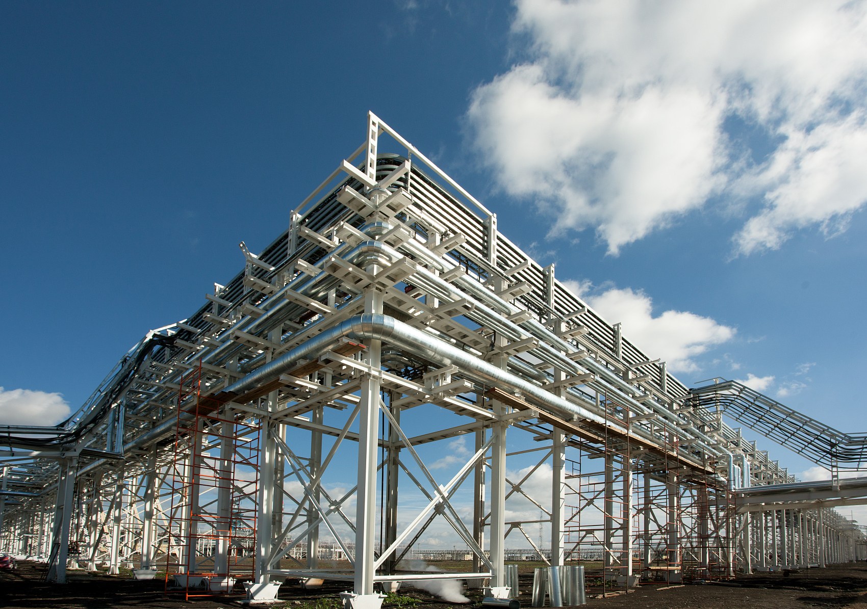
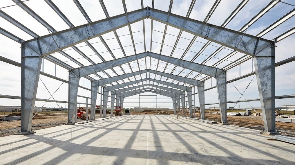
Primary framing member geometry directly impacts total material consumption and foundation reactions. Engineering configurations contrast custom tapered welded H-sections (built-up plate girders) against uniform hot-rolled structural profiles (such as ASTM A992 W-shapes, EN 10025-2 S355JR UB/UC sections, or GB/T 1591 Q355B HEB beams). Tapered welded plate girders reduce overall structural steel deadweight by 18% to 25% compared to uniform hot-rolled profiles. The structural depth of a built-up member expands at the column-rafter eaves haunch and the rafter apex where bending moment envelopes peak, while slimming along regions dominated by lower axial forces. Hot-rolled members offer reduced shop fit-up hours, yet their constant section modulus places surplus tonnage in low-stress zones near pinned column bases.
Primary steel grade compliance across ASTM A572 Grade 50, EN 10025-2 S355JR/J2, and GB/T 1591 Q355B/D with minimum yield strength Fy = 345 to 355 MPa guarantees predictable plastic hinge development. In the fabrication plant, web and flange plates are cut using multi-torch CNC plasma units holding cutting tolerances of ±0.5 mm, then welded via automated submerged arc welding (SAW) per AWS D1.1 and EN 1090-2 Execution Class EXC2 or EXC3. Steel chemistry must remain outside the Sandelin range (maintaining Si < 0.03% or between 0.14% and 0.25% with phosphorus P < 0.02%) to prevent excessive zinc-iron alloy growth during hot-dip galvanizing per ASTM A123 or ISO 1461. Field anchor bolt foundations are held to erection tolerances within ±3 mm to prevent eccentric prying forces at base plates.
Unbraced clear-span portals require rigorous second-order P-Δ stability verification per AISC 360 Chapter C and Eurocode 3 (EN 1993-1-1). Calculations must assess frame sway displacement (P-large-Δ) and local member curvature (P-small-δ) under factored gravity loads combined with either snow or wind suction loads. Serviceability criteria restrict rafter vertical deflection to L/200 to L/300 under total load, while lateral column sway is limited to H/150 for metal-clad bents to avoid fastener fatigue and envelope joint separation.
Table 1: Structural Typology, Consumption Ratios, and Engineering Serviceability Limits
| Clear Span Nominal Width (m) | Standard Bay Spacing (m) | Primary Member Profile Typology | Primary Steel Consumption (kg/m²) | Vertical Deflection Limit (Rafter) | Lateral Sway Limit (Column Eaves) | Governing Design Standard |
|---|---|---|---|---|---|---|
| 12m to 18m | 6.0m | Hot-rolled W-sections / UB profiles | 18 to 24 | L/200 | H/150 | AISC 360-16 / EN 1993-1-1 |
| 20m to 28m | 6.0m to 7.5m | Tapered welded H-section plate girders | 24 to 32 | L/250 | H/150 | AISC 360-16 / EN 1993-1-1 |
| 30m to 38m | 7.5m to 8.0m | Tapered welded H-section plate girders | 33 to 42 | L/250 | H/180 | AISC 360-16 / EN 1993-1-1 |
| 40m to 48m | 8.0m to 9.0m | Deep tapered plate girders with extended haunches | 44 to 58 | L/300 | H/200 | AISC 360-16 / EN 1993-1-1 |
Steel Metallurgy & Hot-Dip Galvanizing: Controlling the Sandelin Range
Hot-dip galvanizing (HDG) of heavy structural sections under ASTM A123 and ISO 1461 requires strict control over steel bath reactivity. As an industrial galvanized portal frame steel structure manufacturer, Shandong XinQiao enforces chemical gatekeeping at the mill procurement stage to eliminate unpredictable iron-zinc diffusion kinetics. The metallurgical behavior of structural steel in molten zinc (typically maintained at 445°C to 455°C) depends directly on silicon (Si) and phosphorus (P) concentrations, as categorized by ASTM A385.
The Sandelin curve defines a zone of severe metallurgical instability. Silicon concentrations between 0.04% and 0.15% trigger hyper-reactive iron-zinc alloy growth. Within this Sandelin instability range, the porous zeta (ζ) intermetallic phase grows unchecked through the liquid boundary layer, consuming the outer ductile eta (η) pure zinc layer. This reaction yields dark gray, excessively thick, and porous coatings that exhibit severe internal shear stress, micro-cracking, and compromised adhesion. Under shop handling, transport vibration, or dynamic service loads, hyper-reactive coatings spall and flake off the steel substrate.
To avoid this failure mode, structural steel procurement specifications must restrict chemistry to either low-silicon steel (Class 1: Si ≤ 0.04%) or silicon-killed steel (Class 3: 0.15% ≤ Si ≤ 0.25%) in accordance with ASTM A385 Table 1. Phosphorus must remain strictly below 0.020% because phosphorus acts as an accelerator, compounding silicon hyper-reactivity and destabilizing the protective delta (δ) phase. For low-silicon heats, XinQiao enforces the Sebisty formula:
Mill sourcing protocols require heat-specific Mill Test Report (MTR) validation combined with secondary Optical Emission Spectrometry (OES) chemical verification on incoming plates (ASTM A992, Q355B, or EN 10025-2 S355JR/J2) before cutting orders proceed to CNC plasma tables (operated to a tolerance of ±0.5 mm).
Table 2: Steel Chemistry Classification, Reactivity Profiles, and HDG Coating Characteristics
| Composition Class | Silicon Range (wt %) | Phosphorus Ceiling (wt %) | Sebisty Index Evaluation | Intermetallic Phase Kinetics | Nominal HDG Thickness (ASTM A123 / ISO 1461) | Surface Quality & Mechanical Adhesion |
|---|---|---|---|---|---|---|
| Class 1 (Low Silicon) | Si ≤ 0.04% | P < 0.020% | Si + 2.5P ≤ 0.09% | Controlled zeta growth; uniform bright eta layer | 85 to 100 μm (610 to 710 g/m²) | High ductility; excellent impact and abrasion resistance |
| Sandelin Range (Hyper-reactive) | 0.04% < Si < 0.15% | P ≥ 0.020% | Si + 2.5P > 0.09% | Runaway zeta phase; absent eta surface layer | 150 to 320 μm (1080 to 2300 g/m²) | Brittle; prone to spalling, flaking, and mechanical delamination |
| Class 3 (Silicon-Killed) | 0.15% ≤ Si ≤ 0.25% | P < 0.020% | Not Applicable | Stable columnar delta and zeta growth | 100 to 125 μm (710 to 890 g/m²) | Uniform matte gray; robust adhesion passing ASTM A123 knife test |
| High Silicon (Hyper-reactive) | Si > 0.25% | P < 0.020% | Not Applicable | Accelerated linear zeta reaction | 130 to 240 μm (930 to 1715 g/m²) | Moderate adhesion; rough finish with heavy zinc buildup on flanges |
For primary structural members with steel thickness exceeding 6 mm, including portal frame tapered columns and rafter moment haunches, ASTM A123 and ISO 1461 mandate a minimum nominal zinc coating thickness between 85 μm and 120 μm (610 to 850 g/m²). Maintaining steel chemistry outside the Sandelin range ensures that the zinc layer develops a ductile metallurgical bond rather than a brittle intermetallic phase. Steel verified against ASTM A385 Class 1 or Class 3 limits withstands high-strength bolt tensioning per AISC 360-16 specifications without edge flaking or micro-cracking at structural joints.
Thermal Distortion Management & ASTM A385 Venting and Drainage Protocols
Immersing structural steel into a molten zinc bath operating at 445°C to 455°C (833°F to 851°F) triggers immediate thermal shock and dramatic metallurgical shifts. At this temperature, the yield strength of structural carbon steel (such as ASTM A992 or Chinese GB/T Q355B) drops by approximately 40% to 50% compared to ambient values. As an established galvanized portal frame steel structure manufacturer, Shandong XinQiao implements rigorous detailing and shop-floor protocols to control the rapid thermal expansion and asymmetric release of residual rolling and welding stresses that occur during kettle immersion.
Non-uniform assemblies, such as tapered plate girders featuring slender webs (tw < 8 mm) joined to thick flanges (tf > 16 mm), represent the highest risk profile for severe thermal distortion. The thin web heats and expands far faster than the heavy flange, creating localized plastic deformation, severe web oil-canning, out-of-straightness, and lateral-torsional bowing. When web-to-flange thickness ratios exceed 1:2.5, differential expansion forces overcome the reduced yield capacity of the hot plate. Fabricators must install intermediate temporary or permanent anti-distortion stiffeners before galvanizing to brace the web against out-of-plane buckling.
| Profile Component Geometry | Web-to-Flange Ratio | Thermal Distortion Risk Level | Required Stiffener Spacing | Pre-Galvanizing Mitigation Protocol |
|---|---|---|---|---|
| Web 6mm / Flange 12mm | 1:2.0 | Moderate | 1.5 × web depth | Alternating staggered fillet welds, standard crane pick points |
| Web 6mm / Flange 16mm | 1:2.67 | High | 1.0 × web depth | Temporary welded diagonal angles, balanced dual-arc welding |
| Web 8mm / Flange 25mm | 1:3.13 | Severe | 0.75 × web depth | Full-depth transverse stiffeners, 1.5mm/6m pre-camber allowance |
| Web 10mm / Flange 32mm | 1:3.20 | Extreme | 0.5 × web depth | Heavy permanent cross-bracing, double-dip temperature profiling |
| RHS / SHS Columns (8mm wall) | 1:1.0 | Low | Internal diaphragms only | Internal corner snipes, external venting holes per ASTM A385 |
Mitigation begins in the fabrication shop before steel reaches the galvanizing yard. Plate cutting on CNC plasma tables maintains tolerances within ±0.5 mm to ensure tight fit-up without forced mechanical clamping that locks in stress. All longitudinal web-to-flange joints are welded using balanced, symmetrical submerged arc welding (SAW) sequences. Dual-head SAW systems deposit fillet welds simultaneously on opposing sides of the web, balancing heat input below 1.8 kJ/mm to minimize residual stresses. Fabricators also apply pre-camber compensation, introducing an upward camber of 1.5 mm per 6 meters of girder length to neutralize thermal sag during immersion. At the galvanizing facility, crane operators suspend assemblies to enter and exit the kettle at an inclination angle between 30° and 45°. This steep angle permits rapid, uniform liquid zinc ingress, equalizes buoyancy forces, reduces thermal gradient dwell time, and accelerates zinc drainage to maintain sweep tolerances within the L/1000 limit specified in EN 1090-2 and AISC 303-16.
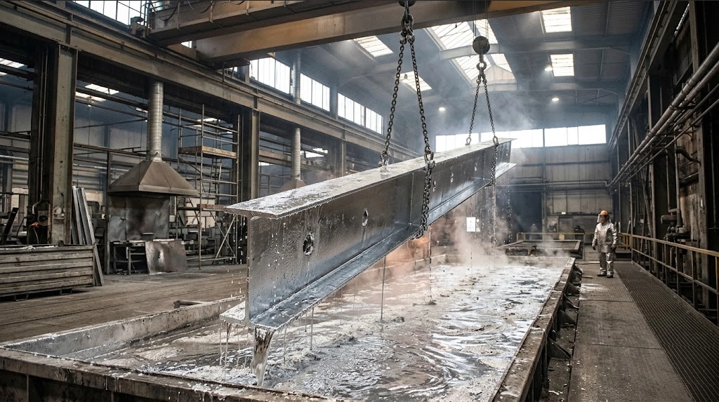
Galvanizing enclosed hollow sections, welded box columns, and complex moment-resisting knee joints introduces acute safety and quality challenges governed by ASTM A385 (Standard Practice for Providing High-Quality Zinc Coatings). Trapped pre-treatment chemicals (degreasing acids and flux solutions) vaporize inside unvented cavities at 450°C, generating steam expansion ratios exceeding 1500:1. These localized pressure spikes cause kettle explosions, tear welded joints apart, and create severe safety hazards.
To prevent trapped air pockets, structural ruptures, zinc ash inclusions, and ungalvanized bare spots, fabricators must provide vent and drain openings positioned at the highest and lowest points of the member in its dipping orientation. Internal vent openings must equal at least 25% to 30% of the internal cross-sectional area of hollow or boxed sections. For hollow structural sections (HSS) with internal diaphragms, gussets, or end-plates, drain holes must be located at the extreme outer corners. Fabricators achieve this by cutting 45° snipes (minimum 30 mm × 30 mm, or up to 50 mm radius corner notches) across the corners of internal plates. These corner cutouts ensure 100% free flow of molten zinc and pre-treatment acids across all surfaces, preventing air locks, avoiding zinc entrapment pockets, and guaranteeing a uniform metallurgical bond throughout the structural frame.
Moment Connection Engineering: Rigid Haunches, Apex Splices & Fastener Mechanics
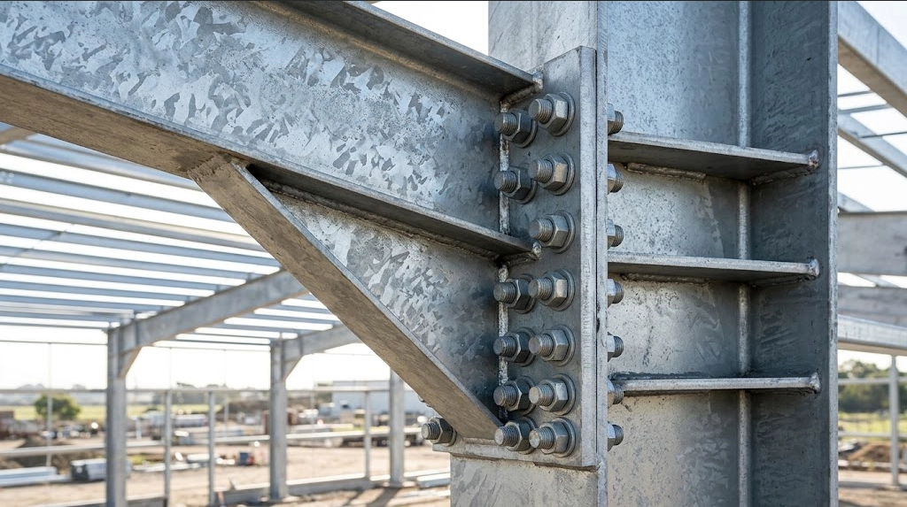
At Shandong XinQiao Steel Structure Co., Ltd., moment-resisting knee and apex joints form the primary lateral load-resisting system for clear-span industrial facilities. As an established galvanized portal frame steel structure manufacturer, our engineering practice integrates strict plastic design principles under AISC 360-16 and Eurocode 3 (EN 1993-1-8). The eaves knee joint must transfer massive negative bending moments and panel shear forces generated by gravity combinations and lateral wind suction. To satisfy rotational stiffness limits while avoiding field-welded field splices, the eaves haunch is cut from parent hot-rolled or welded beam sections using automated CNC plasma systems (holding fabrication cut tolerances to ±0.5 mm) and welded directly to the rafter bottom flange.
The haunch depth is systematically sized between 1.5 to 2.0 times the depth of the parent rafter (hh ≈ 1.5dr to 2.0dr). Its length extends approximately 10% of the total frame clear span. This specific horizontal geometry shifts the bolted moment connection outward to intercept the frame bending moment diagram near its dead-plus-live inflection point, drastically reducing the demand placed on the bolted end-plate splice.
Welding Detailing and Panel Zone Reinforcement
Load transfer across the rafter-to-column interface demands distinct weld specifications. Full-penetration Complete Joint Penetration (CJP) groove welds are mandatory at the rafter top flange and haunch bottom flange interfaces with the end plate. These welds withstand cyclically fluctuating tension and compression forces under reversing load cases. In our shop workflow, these tension flange CJP welds undergo 100% Ultrasonic Testing (UT) per AWS D1.1 Clause 6 and ISO 17640 acceptance Level B prior to surface treatment.
Conversely, double continuous fillet welds are engineered for the haunch web-to-end-plate and haunch web-to-flange connections, sized to resist concurrent longitudinal shear. Within the column panel zone, diagonal web stiffeners or horizontal continuity plates matching the rafter flange thickness are positioned per AISC 360-16 Chapter J and EN 1993-1-8 Section 6.2.6. These prevent local web yielding, web crippling, and shear buckling under localized transverse compression.
Bolted Fastener Performance and Pre-Tensioning Specifications
Field splices use heavy hex, pre-tensioned structural bolting assemblies conforming to ASTM F3125 Grade A325 / A490 or EN 14399 (System HR/HV). Connections are installed as slip-critical (friction-grip) joints, engineered to eliminate joint slip under serviceability limit state (SLS) loading and prevent bolt prying forces from magnifying flange flexure. Pre-tensioning protocols must strictly comply with the Research Council on Structural Connections (RCSC) specification, using verified turn-of-nut methodology or calibrated digital torque wrenches verified daily using a Skidmore-Wilhelm calibrator.
| Bolt Specification | Nominal Grade | Min Tensile Strength (MPa) | Proof Load Yield (MPa) | Installation Protocol | Hydrogen Embrittlement Risk | Galvanizing / Corrosion Protection |
|---|---|---|---|---|---|---|
| ASTM F3125 Grade A325 | Carbon Boron Steel | 830 | 660 | Turn-of-Nut / Calibrated Wrench | Low (Hardness < 34 HRC) | Hot-Dip Galvanized per ASTM F2329 |
| ASTM F3125 Grade A490 | Alloy Steel | 1040 | 830 | Turn-of-Nut with Squirter DTIs | Extreme (Hardness 33–39 HRC) | Mechanical Plating per ASTM B695 Class 55 |
| EN 14399-3 (System HR) | Class 8.8 | 800 | 640 | Combined Torque-Angle Method | Negligible | Hot-Dip Galvanized per ISO 10684 |
| EN 14399-4 (System HV) | Class 10.9 | 1000 | 900 | Torque Pre-load Method | Extreme (Acid absorption) | Zinc Flake Coating per ISO 10683 |
Hydrogen Embrittlement Vulnerabilities in Galvanized Fasteners
Structural failures occur when high-tensile bolts (ultimate tensile strength exceeding 1000 MPa, such as ASTM A490 or ISO 898-1 Class 10.9) are subjected to standard hot-dip galvanizing lines. During the pre-treatment stage, hydrochloric or sulfuric acid pickling generates monoatomic hydrogen. This hydrogen diffuses rapidly into the steel crystalline microstructure. When placed under sustained high tensile preloads, this trapped hydrogen migrates to regions of maximum triaxial stress (such as the thread root and the head-to-shank fillet radius), initiating delayed catastrophic brittle fracture without prior plastic deformation.
Consequently, structural engineers prohibit conventional acid pickling and hot-dip galvanizing for all fasteners with tensile strengths equal to or exceeding 1000 MPa. If Class 10.9 or A490 assemblies are specified, they must be descaled by mechanical blast cleaning rather than chemical pickling. They must receive non-electrolytic zinc flake coatings (per ISO 10683) or mechanical galvanizing (per ASTM B695 Class 55). If acid pickling ever occurs on fasteners exceeding 31 HRC, immediate post-pickling dehydrogenation baking at 190°C to 220°C for a minimum of 4 to 24 hours (governed by ASTM F1941 / ISO 9588) must take place before galvanizing or tightening. For high-durability projects, Class 8.8 and ASTM A325 bolts remain the preferred choice. Their chemistry resists stress-assisted microcracking while delivering proven ductility within rigid moment-frame knee and apex nodes.
If You Want a Second Opinion on Your Portal Frame Design
Evaluating structural efficiency and load-bearing requirements for portal frames requires precise design coordination. At Shandong XinQiao Steel Structure Co., Ltd., our engineering staff verifies member sizing, drift limits, and connection detailing in accordance with AISC 360 and EN 1090 standards. Operating from our 60,000 ㎡ fabrication facility equipped with multi-axis CNC cutting lines, we achieve sub-millimeter tolerances to prevent field fit-up delays.
Atmospheric Corrosion Resistance & ISO 12944 / ISO 9223 Durability Lifespan
As an industrial galvanized portal frame steel structure manufacturer, Shandong XinQiao Steel Structure Co., Ltd. engineers primary and secondary structural members to withstand aggressive microclimates without requiring mid-cycle surface refurbishment. Steel frameworks fabricated from Q355B or ASTM A992 sections undergo hot-dip galvanizing per ASTM A123 or ISO 1461 to create an integrated metallurgical bond. The iron-zinc alloy structure develops gamma and delta phases beneath the zeta layer, capped by an outer eta layer of pure zinc.
Passivation Mechanics and Patina Formation
Zinc patina formation: zinc oxidizes to zinc hydroxide and reacts with atmospheric CO2 to form an insoluble, protective zinc hydroxycarbonate [2ZnCO3·3Zn(OH)2] barrier. When structural members leave the galvanizing kettle, the pure zinc surface immediately reacts with atmospheric oxygen to form zinc oxide (ZnO). Exposure to ambient moisture or precipitation converts this layer into zinc hydroxide [Zn(OH)2]. Over subsequent weeks in freely circulating air, carbon dioxide converts the hydroxide into a dense, insoluble basic zinc carbonate film [2ZnCO3·3Zn(OH)2]. This microcrystalline barrier exhibits low solubility in neutral and alkaline moisture (pH 6.5 to 12.0), drastically retarding the ingress of atmospheric oxygen and moisture to the underlying steel substrate.
Atmospheric Corrosivity Mapping and Zinc Depletion Rates
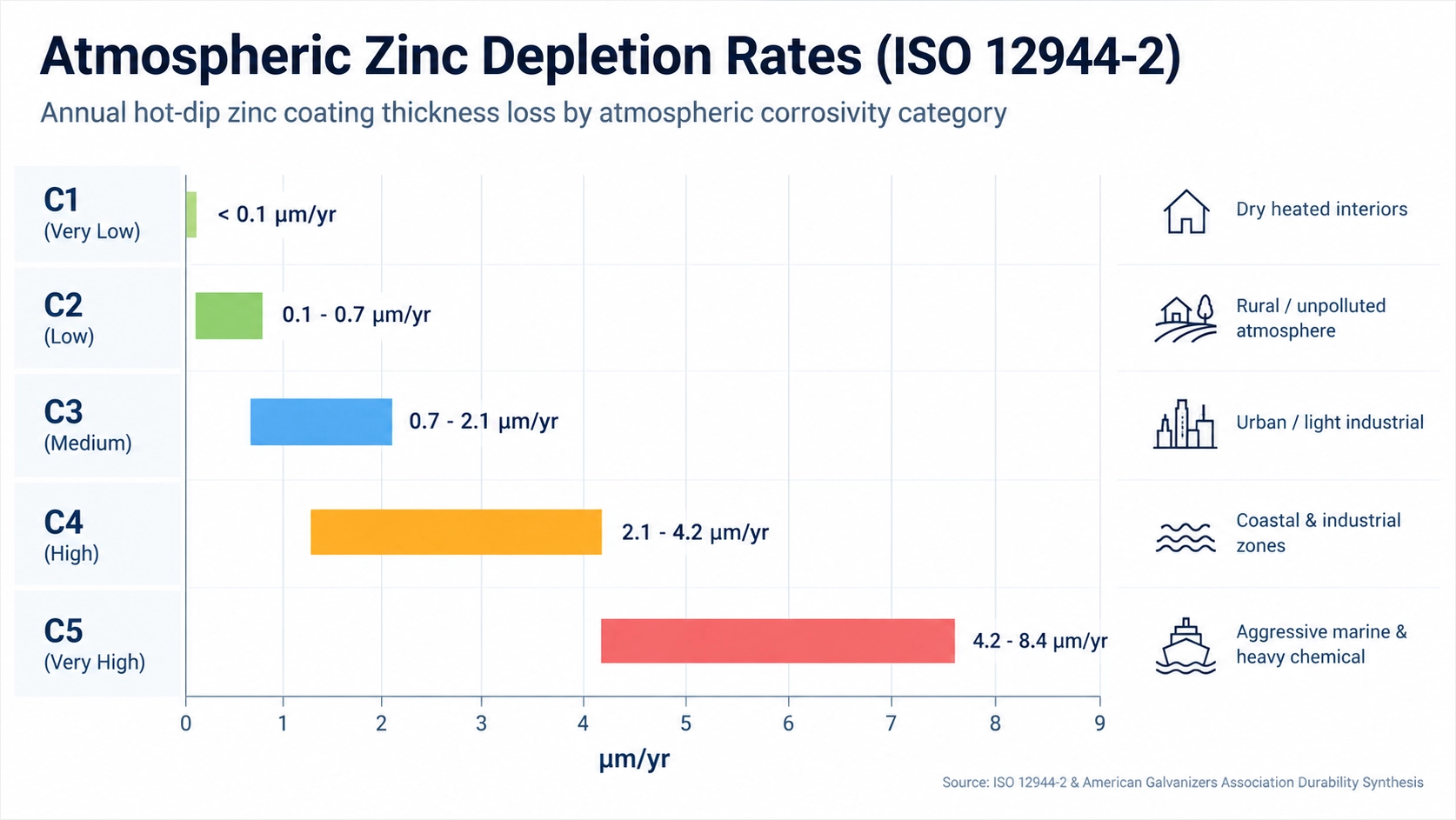
Atmospheric degradation rates govern time-to-first-maintenance (TFM), defined per ISO 12944-5 as the timeframe elapsed until 5% of the structural steel surface exhibits rust breakdown (European Rust Scale Ri 3). Design service life calculations follow ISO 12944-2 / ISO 9223 corrosivity mapping: C3 urban/industrial (0.7–2.1 μm/yr zinc loss) alongside C4 chemical/industrial (2.1–4.2 μm/yr), extending to C5 marine coastal (4.2–8.4 μm/yr). In controlled interior spaces classified as C1, zinc depletion is negligible (<0.1 μm/yr), whereas extreme offshore or industrial environments categorized as CX experience loss rates between 8.4 and 25 μm/yr.
A standard 100 μm hot-dip galvanized coating provides 50+ years of maintenance-free service life in C3 environments and 25 to 45 years in aggressive C4 environments. Standard multi-coat liquid barrier paint systems applied over bare steel (e.g., 80 μm zinc-rich epoxy + 120 μm epoxy MIO intermediate + 60 μm polyurethane topcoat) degrade via ultraviolet chalking and embrittlement. This breakdown results in edge peeling, demanding total recoating within 10 to 15 years in C4 exposure.
Table 3: Atmospheric Corrosivity Mapping, Zinc Depletion, and Service Lifespan
| Corrosivity Category (ISO 12944-2 / ISO 9223) | Typical Operating Environment | Mass Loss of Zinc (g/m²·yr) | Zinc Depletion Rate (μm/yr) | TFM for 85 μm HDG (Years) | TFM for 100 μm HDG (Years) | TFM for 120 μm HDG (Years) | TFM for 250 μm Paint System (Years) |
|---|---|---|---|---|---|---|---|
| C1 (Very Low) | Heated interior storage, low relative humidity | <0.7 | <0.1 | >100 | >100 | >100 | 25 to 30 |
| C2 (Low) | Rural depots, unheated transit sheds, low pollution | 0.7 to 5.0 | 0.1 to 0.7 | 85 to 100+ | >100 | >100 | 20 to 25 |
| C3 (Medium) | Urban processing, industrial inland, light manufacturing | 5.0 to 15 | 0.7 to 2.1 | 40 to 85+ | 50+ | 60+ | 15 to 20 |
| C4 (High) | Chemical storage facilities, coastal zones (low salinity) | 15 to 30 | 2.1 to 4.2 | 20 to 40 | 25 to 45 | 30 to 57 | 10 to 15 |
| C5 (Very High) | Marine shorelines (high chloride), industrial chemical units | 30 to 60 | 4.2 to 8.4 | 10 to 20 | 12 to 24 | 14 to 29 | 5 to 10 |
| CX (Extreme) | Offshore platforms, splash zones, heavy industrial fertilizer | 60 to 180 | 8.4 to 25.0 | 3 to 10 | 4 to 12 | 5 to 14 | 2 to 5 |
Duplex Coating Systems for Severe Chemical and Marine Exposure
In enclosed livestock sheds with concentrated agricultural ammonia, bulk chemical fertilizer depots, and salt processing facilities, standalone galvanizing can suffer accelerated consumption from direct acid-base condensation. For these environments, engineers specify duplex coating systems combining hot-dip galvanizing with an applied liquid coating barrier.
Duplex coatings provide a synergistic multiplication factor (1.5× to 2.3×) extending service life beyond the sum of galvanizing and paint systems individually. The mathematical calculation for duplex lifespan (Lduplex) follows:
where the synergy factor K ranges between 1.5 and 2.3 depending on chemical exposure severity. The overcoating paint protects the galvanized layer from immediate pollutant exposure, while the underlying zinc eliminates undercut corrosion and blistering at localized paint voids.
Fabrication execution demands stringent surface preparation per ASTM D6386 or EN ISO 12944-4. Steel components receive sweep blasting using non-metallic, inert mineral media (garnet or aluminum oxide, particle size 150 to 250 μm) at blast pressures of 0.20 to 0.28 MPa (30 to 40 psi) to generate a surface profile of 20 to 30 μm without fracturing the alloy layers. A 40 μm polyamide-cured epoxy tie-coat is applied immediately, followed by a 100 μm high-build epoxy intermediate and a 50 μm aliphatic polyurethane topcoat, resulting in an impervious, low-maintenance structural envelope.
Fabrication Machinery, Automated Welding & Shop Pre-Assembly Tolerances
As an established galvanized portal frame steel structure manufacturer, Shandong XinQiao executes heavy industrial fabrication through an automated production line designed to eliminate geometric drift. Precision processing begins with primary plate preparation. Raw structural plate (ASTM A572 Grade 50 or EN 10025-2 S355JR/J2) passes through multi-torch CNC oxy-fuel cutting systems for heavy base plates and haunches above 32 mm, while high-definition plasma cutting tables handle webs and flanges up to 32 mm with edge squareness within 1 degree and cutting tolerances under ±0.5 mm.
Cut components transfer directly to automated hydraulic fit-up jigs. These pneumatic and hydraulic clamping stations force web plates and flange plates into continuous mechanical contact under uniform pressure, maintaining exact perpendicularity and zero root opening before tacking.
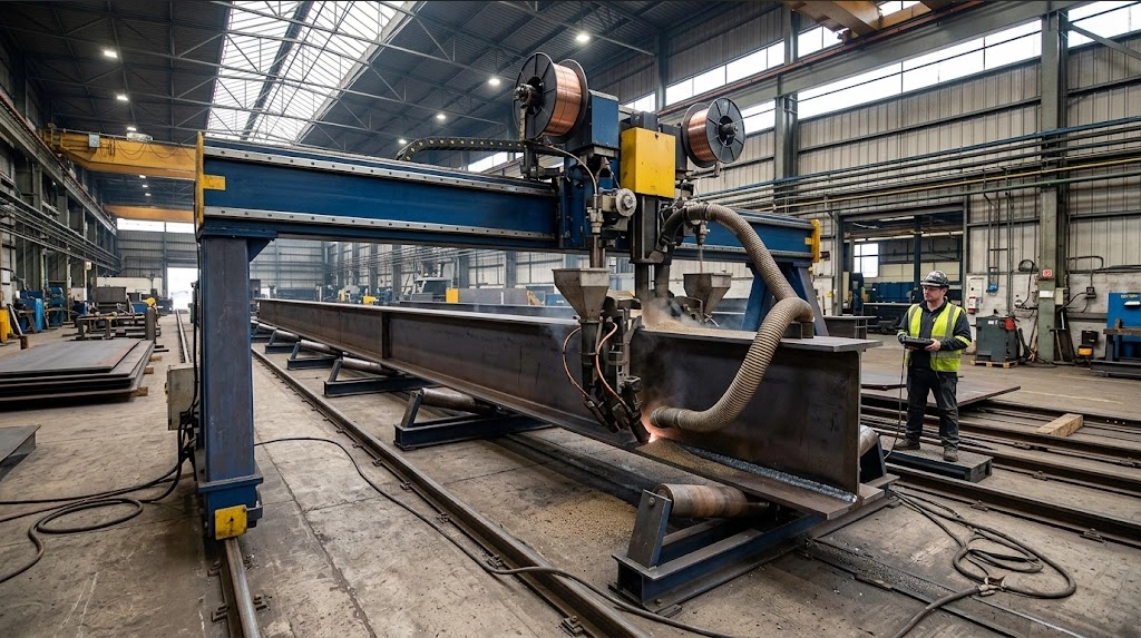
Fit-up assemblies advance to twin-wire submerged arc welding (SAW) portal gantries. Automated Submerged Arc Welding (SAW) lines ensure 100% continuous deep penetration welding with heat input controlled between 1.5 and 2.5 kJ/mm. Maintaining this precise thermal window prevents excessive grain growth and brittle martensite transformation in the heat-affected zone (HAZ), fully satisfying AWS D1.1/D1.1M structural welding codes and EN ISO 15614-1 specifications.
The thermal cycles inherent to submerged arc welding inevitably produce angular distortion across the flange plates. To eliminate this residual deformation, structural members immediately pass through heavy-duty mechanical roll straighteners. Mechanical 3-roller hydraulic flange straighteners correct flange out-of-squareness to within 1/200 of flange width (b/200), ensuring an even, unyielding bearing plane across all structural interfaces.
After straightening, members advance to high-speed 3D multi-spindle CNC drilling lines. By synchronizing three carbide drill heads across three axes simultaneously, the system drills connection holes, purlin cleat patterns, and splice interfaces in one pass. CNC multi-spindle drilling lines achieve hole pitch and center-to-center placement tolerances within ±0.5 mm to guarantee frictionless site erection, eliminating the dangerous field practice of torch-reaming misaligned bolt holes on site.
Prior to surface cleaning, hot-dip galvanizing, or industrial coating application, components enter the pre-assembly staging zone. Any thermal correction, flame straightening, or reaming executed after hot-dip galvanizing destroys the metallurgical zinc-iron alloy layers, exposing bare steel to rapid atmospheric corrosion. Consequently, geometric conformance must be verified at the factory floor.
Shop pre-assembly audit: minimum 10% to 20% random frame trial assembly in-plant verifies span tolerances within ±3.0 mm and column squareness within ±2.0 mm. Factory staging beds accommodate full-scale mockups comprising the portal columns, rafter haunches, apex splices, and crane brackets. Technicians apply laser trackers and calibrated optical transits to audit hole concentricity, rafter pre-camber profiles, member sweep, and mating flange contact angles under unforced fit-up conditions.
| Structural Parameter | XinQiao In-Plant Standard | EN 1090-2 (Class 1 / Class 2) | AISC 303-16 Specification |
|---|---|---|---|
| Overall Member Length (L ≤ 9m) | ±1.5 mm | ±2.0 mm (Class 1) / ±1.0 mm (Class 2) | ±1.6 mm (1/16 in) |
| Overall Member Length (L > 9m) | ±2.5 mm | ±3.0 mm (Class 1) / ±2.0 mm (Class 2) | ±3.2 mm (1/8 in) |
| Flange Out-of-Squareness | b/200 or 1.5 mm max | b/100 (Class 1) / b/200 (Class 2) | b/100 or 6.0 mm max |
| Web Camber Deviation at Midspan | ±2.0 mm from design curve | ±L/500 (Class 1) / ±L/1000 (Class 2) | ±L/1000 or 6.0 mm max |
| Hole Group Center-to-Center Pitch | ±0.5 mm | ±1.0 mm (Class 1) / ±0.5 mm (Class 2) | ±0.8 mm (1/32 in) |
| Bolt Hole Concentricity (Splice) | 100% pin pass at d+0.5 mm | 100% pin pass at d+1.0 mm | Standard clearance pass |
| Column Pre-Assembly Squareness | ±2.0 mm over total height | ±H/500 | ±H/500 |
| Frame Trial Assembly Span Check | ±3.0 mm across clear span | ±5.0 mm | ±4.8 mm (3/16 in) |
These dimensional checks guarantee that rafter assemblies match theoretical roof slope pitches, apex splices seat without forced mechanical jacking, and high-strength structural bolts insert through zinc-coated holes by hand, speeding up crane hook cycles during on-site steel erection.
Quality Assurance, NDT Inspection Protocols & International Compliance Standards
Fabricating export-grade galvanized portal frame steel structures requires a quality management system aligned with governing statutory codes. Structural steelwork shipped across international jurisdictions must satisfy specified structural reliability frameworks. Shandong XinQiao maintains active certification under ISO 9001, ISO 3834-2 for fusion welding quality requirements, EN 1090-2 Execution Class 3 (EXC3 for CE marking), and AISC Certified Fabricator (Building Fabricator - BU). Third-party WPS/PQR qualification by notified bodies (TÜV, BV, SGS, or Lloyd's Register) under ISO 3834-2 verifies that all welding procedures and welder test coupons satisfy European and American design criteria.
Material provenance forms the foundation of this quality architecture. EN 10204 Type 3.1 Inspection Certificates required for all base steel plates, welding consumables, high-strength bolts, and zinc ingots (minimum 99.995% Zn purity per ASTM B6) are validated upon delivery. Steel mill certificates undergo optical emission spectrometry and Charpy V-notch impact validation to confirm heat-specific mechanical properties prior to CNC processing.
Non-destructive testing (NDT) follows a calibrated, multi-stage protocol governed by certified Level II and Level III inspectors. Dimensional fit-up inspections check root gaps, bevel angles, and assembly alignment against shop drawing tolerances of ±1.0 mm for member lengths and ±0.5 mm for bolt pitch.
Welds undergo 100% Visual Testing (VT) per AWS D1.1 and ISO 17637, assessing weld profile geometry, throat thickness, and verifying the complete absence of surface porosity or undercut exceeding 0.5 mm. 100% Ultrasonic Testing (UT) of all Complete Joint Penetration (CJP) tension flange groove welds at rafter-to-column knees per AWS D1.1 Clause 6 / ISO 17640 ensures full cross-sectional fusion through critical moment transfer zones. Magnetic Particle Testing (MT) applied to 20% to 100% of critical shear tabs, stiffeners, and high-stress weld toes per ASTM E709 and ISO 17638 screens for micro-fissuring, lamellar tearing, and stress-induced solidification cracks.
Post-galvanizing inspection verifies corrosion barrier integrity following immersion in molten zinc baths controlled between 445°C and 455°C. Coating thickness measurements are gathered across profiles using calibrated magnetic thickness gauges per ASTM E376 and ISO 2178. For heavy industrial envelopes requiring duplex paint systems over galvanizing, cross-hatch adhesion testing per ASTM D3359 evaluates interface bonding. Post-treatment operations mandate mechanical dressing using pneumatic needle scalers to remove zinc dross, wire nodules, and galvanized slag from splice interfaces, guaranteeing that field bolt seating planes comply with standard erection tolerances without sacrificing zinc barrier performance.
Table 4: Structural Steel Quality Control, NDT Regimen & Acceptance Criteria
| Inspection Stage | Test Method | Reference Standard | Inspection Frequency | Mandatory Acceptance Criteria |
|---|---|---|---|---|
| Raw Material Intake | Spectrometry & Tensile Testing | EN 10204 Type 3.1 / ASTM A6 | 100% of material heats | Chemical composition verified; Zn purity ≥ 99.995% per ASTM B6 |
| CNC Cutting & Preparation | Physical Measurement | EN 1090-2 EXC3 / AISC 303 | 100% cut components | Length: ±1.0mm; Web/flange squareness: ±0.5mm |
| Assembly & Root Fit-up | Mechanical Gauges | AWS D1.1 / ISO 5817 Level B | 100% joints prior to weld | Root opening: ±1.5mm; Bevel angle: ±2.5 deg |
| Fillet & Stiffener Welds | Visual (VT) & Magnetic Particle (MT) | AWS D1.1 / ASTM E709 / ISO 17638 | 100% VT; 20% to 100% MT | Zero cracks; undercut ≤ 0.5mm; zero lack of side fusion |
| Haunch & Knee Moment Welds | Ultrasonic Testing (UT) | AWS D1.1 Cl. 6 / ISO 17640 | 100% of CJP groove welds | AWS D1.1 Table 6.2 Class A; ISO 11666 Acceptance Level 2 |
| Post-Galvanizing Film Build | Magnetic Gauge Measurement | ASTM E376 / ISO 2178 | 5 spot locations per member | Min local: 85 μm; Min mean: 100 μm (t ≥ 6mm) |
| Galvanizing Adhesion | Cross-Hatch / Knife Adhesion | ASTM D3359 / ASTM A123 | 1 test per galvanizing run | Classification 4B or 5B; zero mechanical flaking |
| Mating Surface Dressing | Visual & Feeler Gauge | EN 1090-2 Section 10 / RCSC | 100% connection flanges | Zinc run-free; contact gap ≤ 1.0mm prior to bolt preloading |
Logistics Optimization, Containerized Packaging & Commercial Cost Factors
Export logistics directly govern fabrication economics. As an established galvanized portal frame steel structure manufacturer, Shandong XinQiao Steel Structure Co., Ltd. details primary and secondary structural members to match international multimodal freight constraints. Ocean carriers penalize dead freight volume caused by broken stowage. To minimize container space inefficiencies, portal frames are designed using knock-down, demountable haunch connections and flat-pack bundles configured for standard 40ft High Cube (40' HC) and 40ft Open Top (40' OT) shipping containers.
Container stowage models target payloads between 22 and 26 metric tons per 40ft unit, approaching the permissible gross container mass limits defined in ISO 668. Primary built-up tapered rafters and columns are nested flange-to-web in alternating orientations. For secondary framing, cold-formed thin-walled Z and C purlins achieve up to a 60% shipping volume reduction when nested together in dense modular bundles compared to structural hot-rolled parallel flange channels (PFC) or European standard channels (UPN).
Ocean transit exposes steel surfaces to extreme temperature cycles and relative humidity levels exceeding 90%, creating container rain. Wet storage stain (white rust consisting of zinc hydroxide and zinc oxide) forms rapidly on newly galvanized steel surfaces if moisture is trapped without free air access. To ensure long-term durability and eliminate storage staining, packaging assemblies incorporate kiln-dried, heat-treated hardwood dunnage complying with ISPM 15, 3 mm neoprene isolation pads, and high-tensile 31.75 mm × 0.9 mm steel strapping. Stacks are spaced with 25 mm air gaps to maintain natural ventilation, supplemented by high-absorption calcium chloride desiccant bags distributed throughout the container floor. Where minor surface abrasion occurs during transport, field repairs follow ASTM A780 procedures using organic zinc-rich paints containing at least 65% metallic zinc dust by weight in the dry film.
Procurement evaluations frequently balance the initial capital outlay of hot-dip galvanizing (HDG) per ASTM A123 against multi-coat liquid painting systems applied over Sa 2.5 blast-cleaned steel. Over a 30 to 50-year facility operational horizon in ISO 12944 atmospheric corrosivity categories C3 through C4, hot-dip galvanizing provides superior total cost of ownership (TCO). While paint coatings degrade from solar radiation and mechanical weathering, requiring cyclic touch-ups and full recoats with scaffolding, hot-dip galvanizing reaches complete commercial payback within 8 to 12 years.
| Engineering & Cost Parameter | Hot-Dip Galvanizing (ASTM A123) | Multi-Coat System (ISO 12944 C3/C4 High) |
|---|---|---|
| Surface Preparation Standard | Chemical Pickling (Acid Degrease/Rinse) | Sa 2.5 Abrasive Blast Cleaning (ISO 8501-1) |
| Factory Dry Film Thickness (DFT) | 85 to 100 μm (Metallurgical Alloy) | 80 μm Zinc + 100 μm Epoxy + 60 μm PU |
| Ocean Packaging Density per 40' HC | 22 to 26 metric tons (direct timber nesting) | 18 to 22 metric tons (foam wrap to prevent paint chips) |
| Initial Coating Cost ($/metric ton) | $290 – $360 per ton | $210 – $260 per ton |
| On-Site Erection Damage Vulnerability | Low (impact-resistant alloy layer hardness) | Moderate to High (requires field brush touch-up) |
| Maintenance Interval (First Action) | 35 to 50+ years to 5% substrate rust | 8 to 12 years (spot), 15 years (full recoat) |
| Lifecycle Recoating & Scaffolding Cost | $0.00 over 30-year operational life | $50 – $90 per m² per maintenance cycle |
| 30-Year Total Ownership Cost ($/ton) | $290 – $360 per ton total expenditure | $680 – $1,050 per ton (including field downtime) |
| Breakeven Payback Window | Payback achieved at Year 8 to 12 | Initial CapEx savings lost after first maintenance |
EPC Procurement Due Diligence: Manufacturer Evaluation & RFQ Specification Checklist
When vetting an international galvanized portal frame steel structure manufacturer, EPC procurement managers and Engineers of Record (EOR) cannot rely solely on commercial bids. Physical shop audits, process automation metrics, and metallurgic quality systems dictate whether a pre-engineered portal frame will assemble without on-site modifications or fail under design service loads.
Fabrication Facility Audit Criteria
A fabricator's machinery configuration and facility footprint directly impact dimensional tolerances and coating consistency. EOR and procurement teams must inspect five primary production capabilities before contract award:
Galvanizing bath dimensions must comfortably accommodate long, tapered structural elements. Kettle length must measure at least 12.5 to 15.5 meters, with a minimum width of 1.6 meters and depth of 2.4 meters. Baths under 12.5 meters force progressive dipping (double-end dipping) on standard rafter sections. This practice creates distinct metallurgical overlap zones, uneven thermal expansion cycles that induce member sweep or camber distortions, and localized zinc runs that violate ASTM A123 or EN ISO 1461 thickness limits.
Built-up portal rafters and columns with variable web depths require continuous automated SAW gantry lines running tandem or twin-wire systems (minimum 1,000 A per welding head). Semi-automatic or manual flux-cored arc welding (FCAW) on primary web-to-flange joints introduces stop-start points, increasing internal porosity and incomplete penetration risks under cyclic wind loads.
Shop floor throughput must maintain at least 3,500 to 5,000 metric tons per month. This capacity prevents production bottlenecks on major warehouse contracts and ensures adequate indoor laydown space for staging raw materials, fabricated components, and post-galvanizing inspection.
Structural detailing must be executed using 3D modeling platforms such as Tekla Structures or SDS/2. The fabricator must drive automated CNC drill and saw lines using native DSTV (.NC1) file outputs, while routing thermal plasma cutting through direct numerical control files. Manual hole layout is prohibited. Bolt hole clearances must strictly respect AISC 360-16 Table J3.3 or EN 1090-2 guidelines, holding hole centers to within ±0.8 mm.
The manufacturer must purchase raw plates and coils directly from Tier-1 integrated steel producers. Unverified stockist sourcing without original heat identification risks high carbon equivalent values (CEV exceeding 0.45 per the IIW formula), which causes excessive zinc-iron alloy growth (Sandelin effect) and embrittlement during pickling and dipping.
| Evaluation Category | Minimum EPC Qualification Threshold | Field or Structural Impact of Non-Compliance |
|---|---|---|
| Galvanizing Kettle Length | 12.5 m to 15.5 m length (single dip) | Double-dipping causes heat distortion, brittle zeta phases, and uneven overlaps |
| Automated SAW Capability | Multi-torch gantry with submerged arc welding | Lack of fusion and weld starts/stops in primary web-to-flange connections |
| Detailing and CNC Linkage | Direct Tekla Structures to DSTV/.NC1 execution | Bolt hole placement drift exceeding 1.5 mm, requiring field reaming or structural reject |
| Monthly Plant Throughput | Minimum 3,500 metric tons per month | Project delivery delays, site laydown congestion, and EPC liquidated damages |
| Cutting & Beveling Tolerances | CNC plasma tolerances within ±0.5 mm | Edge gaps exceeding AWS D1.1 root opening limits, causing excessive weld deposition |
Mandatory RFQ Design Data Checklist
An incomplete Request for Quotation (RFQ) package forces structural fabricators to make load assumptions that inflate pricing or compromise structural integrity. EPC tender packages must supply the following explicit project parameters:
- Architectural and Spatial Models: Complete General Arrangement (GA) drawings showing clear heights to eave, bay spacings, clear spans, portal frame haunch clearances, bracing locations, and native 3D building information models (.IFC, .STP, or .TEKLA).
- Governing Regional Design Codes: Precise design baseline specifying ASCE 7 with AISC 360, Eurocode 1 (EN 1991) with Eurocode 3 (EN 1993), or AS/NZS 1170 with AS 4100, including execution class ratings (such as EN 1090-2 EXC2 or EXC3).
-
Environmental and Structural Loadings:
- 3-second gust design wind speed (Vult) in m/s or mph, ground elevation, internal pressure coefficient (GCpi), and topographic exposure category (B, C, or D per ASCE 7).
- Ground snow load (Pg), snow drift parameters, rain-on-snow surcharges, and roof live loads.
- Seismic spectral response accelerations (Ss and S1), site class, seismic importance factor (Ie), and designated Seismic Design Category (A through F).
- Serviceability deflection limits for frame sway (H/150 to H/400) and rafter vertical deflection (L/180 to L/360).
QA Deliverables and Warranty Thresholds
The contract must require four certified quality control deliverables prior to dispatch:
Material certifications per EN 10204 Type 3.1 matching stamped heat numbers, validating chemical composition and mechanical properties (minimum Charpy V-Notch impact values of 27 J at 0°C or −20°C).
Approved Weld Procedure Specifications (WPS), Procedure Qualification Records (PQR), and Welder Performance Qualifications (WPQ) per AWS D1.1 or ISO 15614-1, alongside 100% visual inspection (VT) and minimum 10% to 20% UT/MT records for full penetration welds.
Calibrated magnetic dry-film thickness (DFT) records demonstrating compliance with ASTM A123 (minimum 85 to 100 microns local average for structural steel over 6 mm thick) or ISO 1461.
A formal, manufacturer-backed 20- to 30-year non-perforation corrosion warranty based on site corrosivity category (C1 to C4 per ISO 12944-2), verified by cyclic salt spray testing (ASTM B117 / ISO 9227) and audited by an independent third-party agency (SGS, TÜV, or BV).
Conclusion & Engineering Verdict
Core Structural Verdict
Moment-resisting haunch connections must satisfy AISC 360-16 and Design Guide 1 criteria. Foundation anchor rods must resolve lateral horizontal thrust via hairpin rebar or tie rods whenever base thrust exceeds 85 kN per footing.
Ready When You Are to Talk Steel
Direct communication between project engineers and the fabrication floor eliminates drafting discrepancies and on-site rework. Shandong XinQiao executes heavy industrial fabrication strictly under AWS D1.1 welding standards and certified factory production controls, supported by complete material traceability. When your schedule requires reliable lead times and code compliance, consult with our structural engineering team on your prefab steel warehouse project to review foundation load reactions, crane rail tolerances, and shipment phasing.
Governing Engineering Codes & References
Base Plate and Anchor Rod Design (Second Edition)
Fisher, J. M., & Kloiber, L. A. • American Institute of Steel Construction (2006)
Building Code Requirements for Structural Concrete (Chapter 17: Anchoring to Concrete)
American Concrete Institute (2019)
Standard Specification for Anchor Bolts, Steel, 36, 55, and 105-ksi Yield Strength
ASTM International (2020)
Code of Standard Practice for Steel Buildings and Bridges (Section 7.5)
American Institute of Steel Construction (2022)
Eurocode 3: Design of steel structures — Part 1-8: Design of joints
European Committee for Standardization (CEN)
Eurocode 2: Design of concrete structures — Part 4: Design of fastenings in concrete
European Committee for Standardization (CEN)
Execution of steel structures — Part 2: Technical requirements for steel structures
European Committee for Standardization (CEN)
Mechanical properties of fasteners made of carbon steel and alloy steel
International Organization for Standardization (ISO)
Upstream Precision: How XinQiao Steel Eliminates Site Erection Headaches
The smoothest construction projects are those where the risk of field error is engineered out long before steel leaves the fabrication plant. When building in remote overseas destinations where specialized heavy equipment and certified rigging crews are expensive, prefabricated structural components must fit together seamlessly upon arrival.
Operating a 60,000 ㎡ heavy industrial steel manufacturing facility in Taian, China, XinQiao Steel (Shandong XinQiao Steel Structure Co., Ltd.) solves overseas assembly challenges at the fabrication source: