PEB Clear Span Portal Frame Warehouse Supplier Selection Guide
Source qualified PEB clear span portal frame warehouse suppliers. Compare AISC/MBMA specs, solid-web vs. hybrid truss span boundaries, haunch moment connections, pinned vs. fixed foundation costs, 360° standing seam wind uplift, and turnkey vs. FOB pricing.

Specialist in industrial PEB detailing, AISC 360 connection design, and overseas turnkey project delivery at Shandong XinQiao Steel Structure Co., Ltd.
Table of Contents & Quick Navigation
Engineering Demands of Modern Clear-Span Logistics: Why Column-Free Portals Dominate
Modern high-bay fulfillment hubs demand clear eave heights from 9.0m to 15.0m with zero mid-span foundation penetrations. Selecting a qualified PEB Clear Span Portal Frame Warehouse Supplier is no longer just a structural line-item decision; it directly dictates the operational efficiency and spatial economics of an automated supply chain facility. In traditional multi-span portal frames, interior pipe columns or built-up I-sections impose physical barriers that restrict rack layout flexibility, penalize slab design, and introduce ongoing collision risks. Clear-span rigid portal frames eliminate structural column-strike hazards from material handling equipment (MHE) and forklift operations, removing the hazard of localized structural collapse and progressive frame instability governed by AISC 360-16 impact considerations.
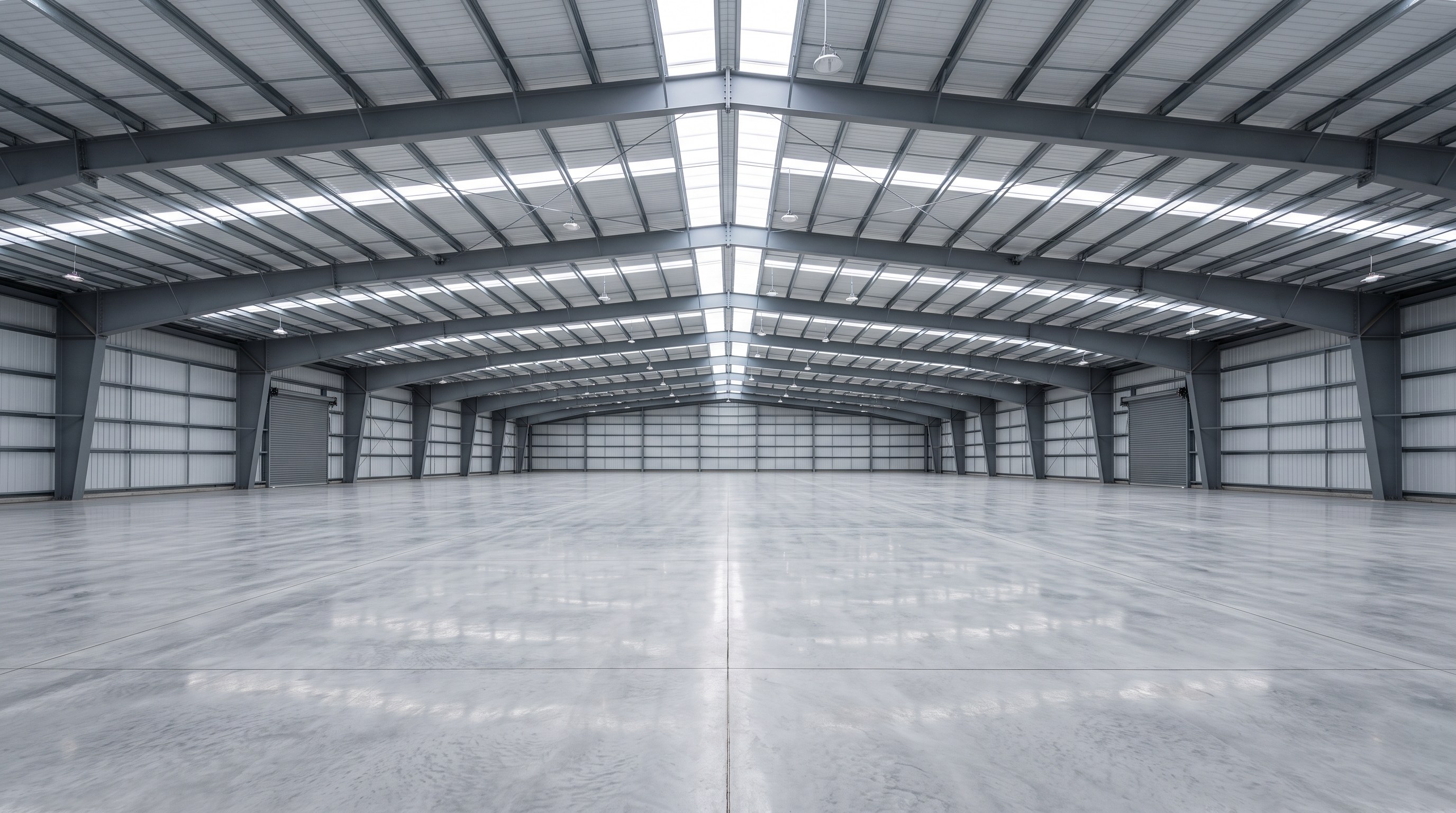
Unobstructed internal floor plates increase volumetric warehouse storage density by 18% to 25% compared to interior column grids. Automated Guided Vehicle (AGV) routing corridors require continuous, millimetric spatial predictability without column detour penalties. In Very Narrow Aisle (VNA) racking configurations, an interior column offset of just 150 mm can interrupt an entire storage run, eliminating tens of high-bay pallet positions. Furthermore, flexible manufacturing facilities rely on unobstructed building envelopes to reconfigure production lines, robotic cells, and overhead crane coverage zones without expensive foundation underpinning or structural modification.
| Parameter | Multi-Span (with Center Columns) | Clear-Span Rigid Frame (36m - 48m) | Engineering Impact / Design Standard |
|---|---|---|---|
| Structural Framing Intensity | 28 to 36 kg/m² | 38 to 48 kg/m² | Primary tapered rafters designed per AISC 360-16 LRFD |
| Usable Volumetric Floor Area | Base Index (100%) | 118% to 125% (+18% to +25%) | Eliminates column dead zones and pallet clearance setbacks |
| MHE / AGV Routing Interference | High (1.5m buffer required per column) | Zero internal obstructions | Eliminates column-strike hazards per OSHA / ISO 3691-4 |
| Foundation Layout Complexity | Multiple interior spread footings | Perimeter moment-resisting pedestals only | Avoids mid-slab saw-cut and isolation joint conflicts per ACI 360R-10 |
| Superflat Floor Slab Feasibility | Disrupted by interior footings and joints | Continuous pours achievable (FF 50 / FL 35 or higher) | Eliminates differential settlement across internal rack bays |
For EPC contractors, structural consultants, and project developers, procurement criteria must extend beyond simple price-per-ton metrics. Fabricating high-span portal frames (spanning 36m to over 60m without intermediate supports) demands stringent quality control. Tapered built-up members manufactured from ASTM A572 Grade 50 or Q355B plate require submerged arc welding (SAW) conforming to AWS D1.1, executed under tight thermal management to prevent web oil-canning and flange tilt per AWS D1.1 Section 5.23. CNC plasma cutting tolerances must be maintained within ±0.5 mm, anchor bolt layout tolerances kept within ±3 mm per AISC 303-16 Section 7.5, and structural surfaces blast-cleaned to ISO 8501-1 Sa 2.5 with a minimum 80 μm DFT epoxy zinc-rich primer. Evaluating a fabricator on these shop-floor execution standards ensures long-term frame serviceability under both dead-load deflections and high-wind lateral drift limitations per AISC Design Guide 3.
Structural Typologies and Span Limits: Solid-Web Tapered Portals vs. Hybrid Truss Systems
Selecting the correct structural framing typology governs the material efficiency, fabrication economics, and structural integrity of industrial buildings. As an established PEB Clear Span Portal Frame Warehouse Supplier, Shandong XinQiao Steel Structure Co., Ltd. delineates structural systems by clear-span capability, plate slenderness boundaries, and logistics envelopes. Primary framing is categorized across three distinct thresholds: standard clear spans (18m to 48m), extended clear spans (48m to 60m), and ultra-wide spans (60m to 180m).
Solid-web tapered portal frames achieve peak structural steel weight efficiency between 24m and 42m clear spans. Within this standard operational threshold, automated submerged arc welding lines assemble custom plate girders cut from ASTM A992 or GB Q355B steel using CNC multi-torch oxy-fuel tables calibrated to ±0.5 mm tolerances. Tapering the rafter profile to match the moment envelope reduces dead load, keeping steel consumption within an economical 24 to 38 kg/m². Rafter sections are factory blast-cleaned to Sa 2.5 standards and primed with 80 micrometers dry film thickness (DFT) epoxy zinc-rich coatings before dispatch.
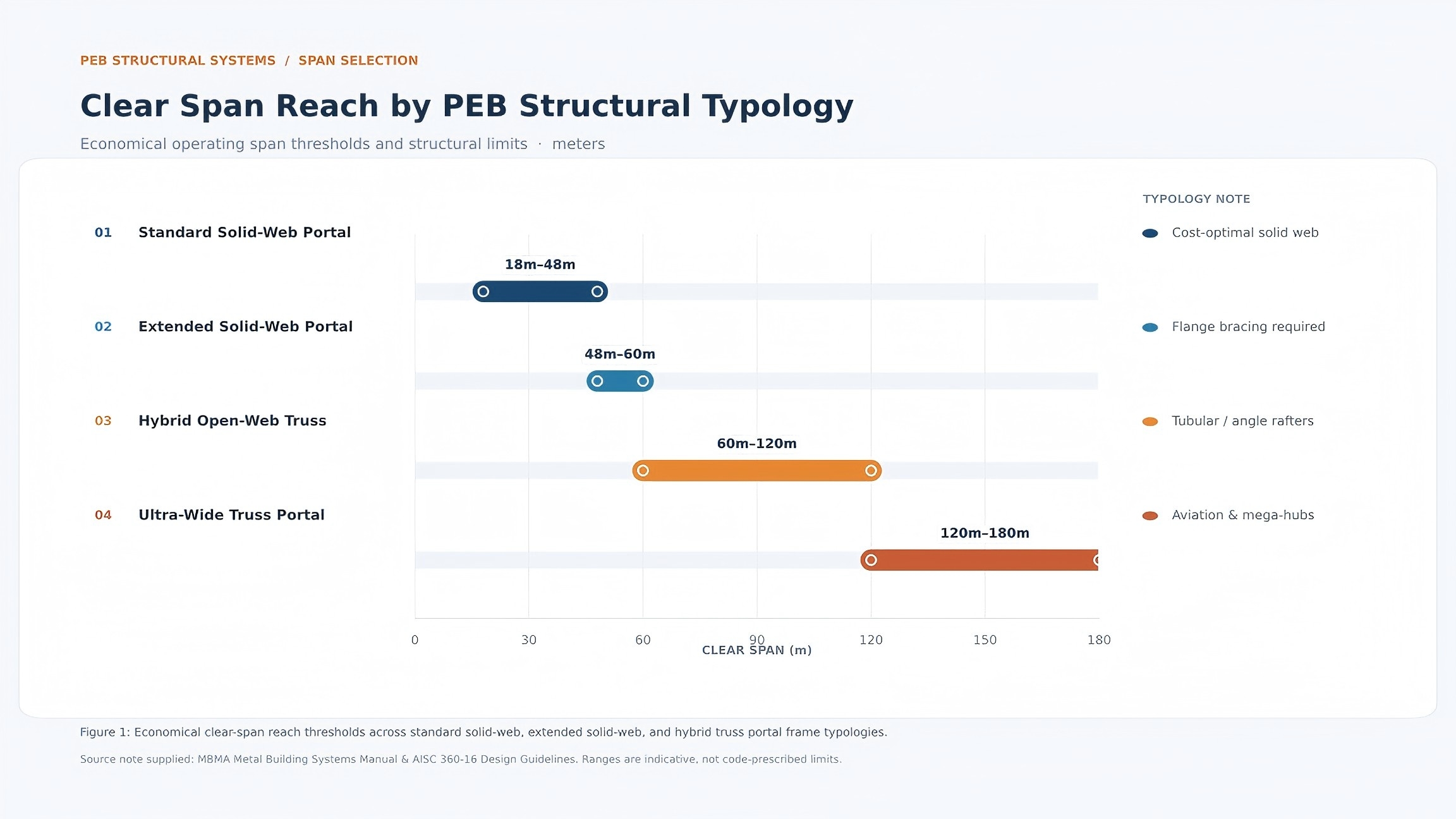
When building footprints require extended spans between 48m and 60m, solid-web systems encounter diminishing economic returns. Rafter haunch depths must expand past 1,800 mm to resist service load bending moments. Clear spans exceeding 60m in solid-web geometry experience severe lateral-torsional buckling risks and transport restrictions for rafter sections deeper than 2.4m. Per AISC 360-16 Table C-B4.1b, thin-web geometries exceed critical web slenderness limits, demanding extensive transverse web stiffeners, lateral fly bracing, and full-penetration groove welds that escalate shop labor hours. Furthermore, shipping profiles exceeding 2.4 meters cannot fit into standard 40-foot flat-rack or open-top shipping containers, requiring specialized flatbed transport that increases freight overhead.
Hybrid open-web and structural tubular truss portals scale cost-effectively from 60m up to 180m clear span for specialized aviation and mega-distribution facilities. For spans exceeding 60m, advanced industrial fabricators transition from solid-web profiles to hybrid truss rafters. These open-web designs use cold-formed square and rectangular hollow sections (ASTM A500 Grade B/C) or built-up structural tees for the top and bottom chords, connected by double-angle web diagonals. By resolving bending moments into pure axial tension and compression forces, open-web trusses maintain rafter self-weight efficiency while preventing plate shear buckling. For mega-hangars spanning up to 180m without interior columns, three-dimensional tubular space trusses provide superior torsional rigidity and accommodate massive overhead crane runway systems without exceeding the L/240 serviceability deflection limit prescribed by AISC Design Guide 3.
Table 1: Clear Span Typology Comparison: Solid-Web Tapered I-Frames vs. Hybrid Tubular/Open-Web Trusses
| Span Category | Clear Span Range (m) | Framing Typology | Primary Steel Weight (kg/m²) | Primary Governing Limit State | Shop Fabrication Labor ($/MT) | Max Shipping Envelope |
|---|---|---|---|---|---|---|
| Standard Clear Span | 18m - 48m | Solid-Web Built-up Tapered I-Section | 24 - 38 kg/m² | Haunch Flexural Yielding (AISC 360-16 F2) | $280 - $380 | 1.6m Depth / 12.0m Length (40ft Container) |
| Extended Clear Span | 48m - 60m | Solid-Web Tapered I-Section with Haunch Stiffeners | 40 - 58 kg/m² | Lateral-Torsional & Web Buckling (AISC 360-16 F4) | $390 - $520 | 2.4m Depth / 13.5m Length (Flat Rack) |
| Ultra-Wide Clear Span | 60m - 120m | Hybrid Tubular / Double-Angle Open-Web Truss | 36 - 54 kg/m² | Chord Axial Buckling & Punching Shear (CIDECT) | $550 - $750 | 3.2m Segment Modular Knock-down |
| Mega-Span Clear Span | 120m - 180m | 3D Spatial Tubular Lattice Girder / Space Frame | 52 - 82 kg/m² | Global Deflection (L/240) & Node Fatigue | $780 - $1,100 | Prefabricated Node & Tube Field Splice Kits |
Structural anchor bolt placement for these systems must maintain a field tolerance of ±3 mm per AISC Design Guide 1 Section 2.3 to ensure proper load transfer into reinforced concrete footings. Choosing the correct structural boundary mitigates erection risk, lowers material consumption, and guarantees compliance with EN 1090-2 Execution Class 3 guidelines.
Metallurgical Specifications and International Fabrication Codes (AISC, MBMA, AWS, GB/T)
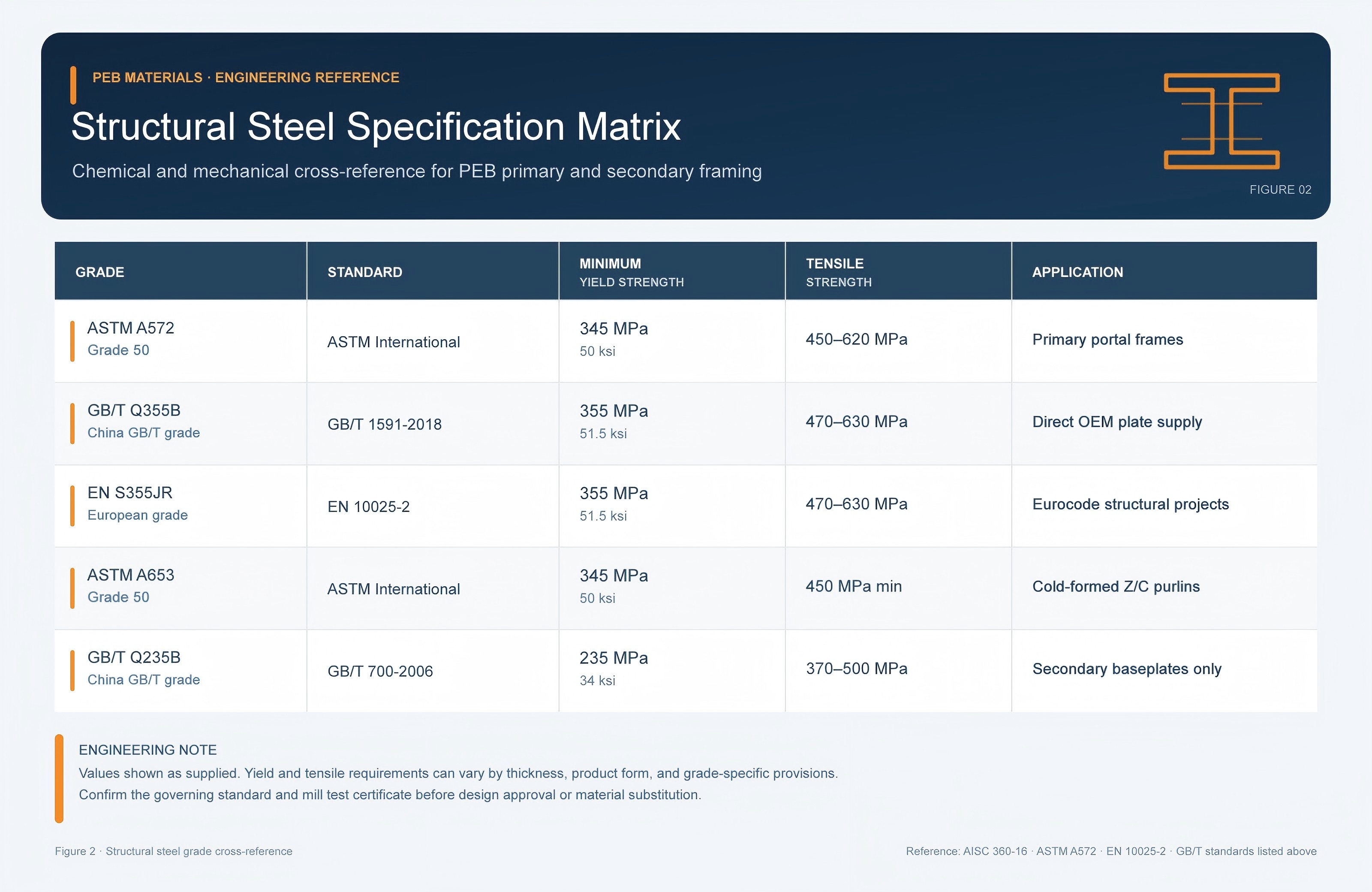
Engineering clear-span steel buildings requires exact conformance to structural design codes and strict metallurgical verification. As a qualified PEB Clear Span Portal Frame Warehouse Supplier, Shandong XinQiao executes all structural designs in strict accordance with AISC 360-16/22, the Metal Building Manufacturers Association (MBMA 2024), EN 1993-1-1 (Eurocode 3), and AWS D1.1/D1.1M structural welding provisions. Primary framing plates must maintain minimum yield strength Fy = 345 MPa (50 ksi) via ASTM A572 Gr 50, Q355B, or S355JR. Mill test certificates (MTCs) per EN 10204 Type 3.1 must trace heat numbers directly to chemical composition limits (carbon equivalent CEV ≤ 0.44% per AWS D1.1 Table 3.1) and Charpy V-Notch (CVN) impact toughness.
Uncontrolled plate substitution represents a severe structural failure risk in international procurement. Uncontrolled plate substitution of Q235B (Fy = 235 MPa) results in a 31.8% deficit in bending moment capacity if section modulus is unadjusted. Low-tier fabricators frequently attempt to substitute commercial-grade Q235B plate into web and flange locations to reduce steel procurement costs. Under maximum factored design load combinations (1.2D + 1.6L or 1.2D + 1.0W), this yield reduction induces premature plastic hinge formation at the haunch and mid-span rafter splices, precipitating catastrophic frame deflection or stability failure.
Table 2: Structural Steel Grade and Specification Cross-Reference
| Specification / Standard | Material Grade | Min Yield Strength Fy (MPa / ksi) | Min Tensile Strength Fu (MPa) | CVN Impact Energy Rating | Primary Structural PEB Application |
|---|---|---|---|---|---|
| ASTM A572 / AISC 360 | Grade 50 (Type 1) | 345 / 50.0 | 450 | 27 J at −20°C (when specified) | Welded tapered columns, rafter flanges, and webs |
| GB/T 1591-2018 | Q355B | 355 / 51.5 | 470 - 630 | 34 J at +20°C | Main portal frames, crane bracket stiffeners |
| GB/T 1591-2018 | Q355D | 355 / 51.5 | 470 - 630 | 34 J at −20°C | Sub-zero clear-span buildings, high dynamic impact |
| EN 10025-2 | S355JR | 355 / 51.5 | 470 - 630 | 27 J at +20°C | European-compliant main frame components |
| ASTM A36 / GB/T 700 | A36 / Q235B | 235 - 250 / 34 - 36 | 370 - 500 | 27 J at +20°C (Q235B only) | Secondary base plates, non-moment end stiffeners |
Shop fabrication protocols enforce tight dimensional controls and automated joining processes. Automatic Submerged Arc Welding (SAW) per AWS D1.1 must govern all primary column and rafter web-to-flange continuous fillet welds. Pre-qualified double-sided SAW guarantees deep root penetration, eliminating manual stick weld defects such as porosity, slag inclusions, and undercut. CNC plasma cutting tables maintain cutting edge squareness within ±0.5 mm to prevent fit-up gaps exceeding the 1.5 mm tolerance mandated by AWS D1.1 Clause 5.22.
Quality assurance requires mandatory Non-Destructive Testing (NDT): 100% Visual Testing (VT) per AWS D1.1 Table 8.1, minimum 20% Ultrasonic Testing (UT) on complete joint penetration (CJP) column-to-base and haunch moment welds per AWS D1.1 Clause 8, and Magnetic Particle Testing (MT) across all high-stress web-to-flange transitions. For environmental durability, all structural members undergo centrifugal wheel shot-blasting to ISO 8501-1 Sa 2.5 (SSPC-SP 10 Near-White Blast) to remove all mill scale and achieve a surface profile of 45 to 75 microns. Corrosion protection is completed with a two-pack epoxy zinc-rich primer system achieving 80 μm to 120 μm Dry Film Thickness (DFT), certified for ISO 12944 C3/C4 industrial atmospheres.
Haunch Moment Connection Detailing and Lateral-Torsional Buckling Mitigation
The structural efficiency of a clear-span portal frame relies on the moment capacity of its primary joints. As an experienced PEB Clear Span Portal Frame Warehouse Supplier, Shandong XinQiao designs portal frame knee assemblies to resist extreme flexural and shear demands. The negative bending moment at the portal frame knee joint reaches its mathematical peak at the rafter-to-column haunch connection. To manage these rotational forces without resorting to excessively heavy rolled profiles across the full span, structural engineers incorporate a fabricated haunch cut.
Geometric proportioning dictates that the overall haunch depth at the column face ranges from 1.5 to 2.0 times the nominal rafter depth (dh = 1.5dr to 2.0dr). The haunch length typically extends 10% to 15% into the clear frame span, terminating where the bending moment curve drops to a level safely resisted by the un-haunched rafter section. Flange and web plates for these built-up sections are cut on multi-torch CNC plasma tables to within ±0.5 mm tolerances, joined via submerged arc welding (SAW) per AWS D1.1 specifications.
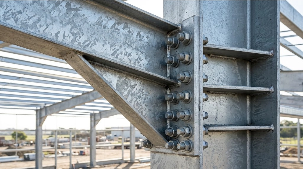
Moment transfer across the rafter-to-column interface depends on extended end-plate configurations governed by AISC Design Guide 16 and AISC Design Guide 39. Connection plates are fitted with high-strength structural bolts: pre-tensioned ASTM A325 or ASTM A490 bolts (or ISO 8.8 and ISO 10.9 equivalents). These fasteners operate in bearing or slip-critical friction-grip configurations. End plates must maintain strict flatness tolerances (maximum 1.0 mm deviation post-welding) to prevent prying forces from magnifying bolt tension loads.
Under-designed haunches lacking full-depth continuity stiffeners suffer local web yielding per AISC 360-16 Chapter J. Concentrated compressive forces delivered by the bottom flange of the rafter drive crippling stresses into the column web panel zone. To prevent web buckling, web crippling, and panel shear failure, engineers must detail three distinct plate reinforcements:
- Horizontal continuity plates align with the column flanges to transfer tension and compression couples.
- Diagonal web stiffeners across the column panel zone when shear stress exceeds the limit states of AISC 360-16 Section J10.6.
- Transverse bearing stiffeners at the termination point of the haunch cut where the bottom flange transitions angle.
A widespread failure mode in low-bid portal frames stems from omitting secondary diagonal braces. Inner bottom flanges of the haunch rafter enter intense compression under gravity loading, requiring direct diagonal fly bracing to purlins at intervals not exceeding 2.0m to 3.0m. Under standard dead and live loading combinations, the top flange remains in tension while the bottom flange experiences high compression. Because roof sheeting connects exclusively to the top flange via cold-formed Z-purlins, the bottom compression flange remains unconstrained unless restrained laterally.
If a fabricator omits diagonal angle fly bracings (L50×50×4 mm or L65×65×5 mm) between the haunch bottom flange and the adjacent roof purlins, the unsupported unbraced length (Lb) exceeds the limiting unbraced length for inelastic lateral-torsional buckling (Lr) specified in AISC 360-16 Table C-B4.1E. This omission triggers catastrophic out-of-plane lateral-torsional buckling (LTB) long before the rafter reaches its intended plastic moment capacity (Mp).
| Clear Span (m) | Haunch Depth Ratio (dh / dr) | End-Plate Thickness (mm) | Pre-Tensioned Bolt Spec | Max Fly Brace Spacing (m) | Governing Web Limit State |
|---|---|---|---|---|---|
| 24 | 1.50 - 1.65 | 20 - 24 | M20 / 3/4 in ASTM A325 | 2.8 | Web Local Yielding |
| 30 | 1.60 - 1.75 | 24 - 28 | M24 / 7/8 in ASTM A325 | 2.5 | Web Compression Buckling |
| 36 | 1.70 - 1.85 | 28 - 32 | M24 / 1 in ASTM A490 | 2.2 | Web Crippling / Panel Shear |
| 48 | 1.85 - 2.00 | 32 - 40 | M30 / 1-1/8 in ASTM A490 | 2.0 | Panel Zone Shear Yielding |
Preventing premature stability failures requires tying every haunch transition into a braced structural node. Cold-formed purlins alone cannot stabilize the bottom flange against rotation without diagonal fly bracing struts creating a rigid force path back into the diaphragm plane. Shandong XinQiao mandates dual-sided fly bracing at the haunch tip and at least two intermediate diagonal struts along the haunch taper to preserve structural integrity through extreme wind and gravity events.
The fastest way to fix this
Mitigating structural fit-up errors and erection schedule overruns requires verified shop fabrication tolerances before components ship to the site. Across our 60,000 m² production facility, Shandong XinQiao Steel Structure Co., Ltd. operates automated CNC plasma cutting, multi-spindle drilling, and submerged arc welding lines to maintain sub-millimeter member accuracy under AISC 360, AWS D1.1, and EN 1090 quality management protocols. To examine member schedules or coordinate custom column grid designs, review our prefab steel warehouse fabrication capabilities and discuss your structural criteria with our engineering department.
Foundation Boundary Conditions: Pinned vs. Fixed Column Bases and Civil Cost Impact
Evaluating column base fixity represents the critical structural interface where superstructure engineering intersects directly with civil geotechnical costs. In clear-span portal frame engineering, base connections are classified as either nominally pinned or moment-resisting (fixed) according to AISC Design Guide 1 (Base Plate and Anchor Rod Design). Pinned column bases require only simple 4-bolt anchor configurations with minimal foundation embedment depth and zero design moment transfer. Under this structural boundary condition, the concrete footing resists only gravity axial loads (P) and horizontal shear thrust (V). The primary bending moments concentrate at the column-to-rafter haunch connections, requiring deeper built-up column profiles (Zx) while leaving the concrete substructure footprint compact and concentric.
Conversely, fixed column bases enforce rotational restraint at the base plate interface. This boundary stiffness curbs lateral drift and reduces positive eave bending moments, which allows for lighter structural columns and rafters. However, this theoretical steel optimization introduces massive overturning bending moments into the substructure. Fixed-base designs can reduce steel superstructure weight by 10% to 14% but increase concrete footing volume by 35% to 60% to resist overturning moments. The resulting load eccentricity (e = M/P) shifts soil bearing pressure distributions into severe triangular or trapezoidal profiles, demanding enlarged concrete pads, deep ASTM F1554 anchor cages, and supplementary rebar hairpins engineered to ACI 318-19 Chapter 17 provisions.
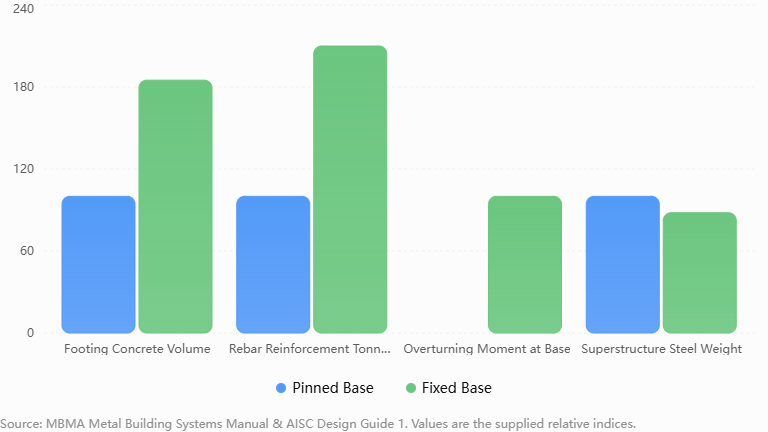
A common value-engineering pitfall occurs when an overseas PEB Clear Span Portal Frame Warehouse Supplier quotes low structural tonnage by modeling fixed base supports without evaluating site-specific soil mechanics. Suppliers quoting competitive FOB steel tonnage with fixed bases often cause a net 15% increase in total project civil substructure expenditure. The general contractor saves marginally on fabricated structural steel weight but incurs substantial extra costs in excavation, formwork, rebar tonnage, and concrete pumping.
Pinned bases remain economically mandatory across project sites characterized by low allowable soil bearing capacities (qa < 150 kPa), shallow groundwater tables, or standard isolated spread footings. Moment-resisting fixed bases are structurally justified only when operational constraints demand strict lateral stiffness, such as warehouses with heavy overhead bridge cranes (e.g., capacities exceeding 10 metric tons) requiring crane runway drift limits of H/400 to H/500 per AISC 360-16 Commentary Table C-B4.1E, or high-bay facilities exceeding 12 meters in clear height.
Table 3: Foundation Mechanics and Civil Cost Comparison: Pinned Base vs. Fixed Base Portal Frames
| Structural Parameter | Pinned Base Portal Frame | Fixed Base Portal Frame | EPC Substructure & Cost Impact |
|---|---|---|---|
| Moment Transfer (Mu) | Zero (Mu ≤ 0.1Mp) | Substantial (Mu ≈ 0.6 to 0.85Mrafter) | Fixed requires heavy moment-arm anchor patterns |
| Anchor Rod Configuration | 4 rods (ASTM F1554 Gr. 36) within web zone | 8 to 12 rods (ASTM F1554 Gr. 55/105) outside flanges | Fixed demands rigid CNC templates (±3 mm tolerance) |
| Foundation Embedment Depth | 400 mm to 600 mm standard pedestal | 900 mm to 1500 mm reinforced pedestal | Fixed increases excavation depth and formwork area |
| Concrete Footing Footprint | Compact (1.8 m × 1.8 m × 0.5 m) | Expanded (3.2 m × 3.2 m × 0.9 m) | Fixed increases pad concrete volume by 35% to 60% |
| Superstructure Steel Weight | Baseline (100% nominal tonnage) | Reduced (86% to 90% nominal tonnage) | Fixed cuts FOB steel weight by 10% to 14% |
| Soil Bearing Pressure Profile | Uniform trapezoidal distribution | Highly eccentric triangular distribution | Fixed risks soil edge yielding on soft clays |
| Total Civil Substructure Cost | Baseline (1.00×) | Cost increase (1.35× to 1.55×) | Fixed shifts 15% net cost penalty onto foundation civil scope |
Secondary Cold-Formed Framing: Continuous Z-Purlin Lapping and Sag Rod Mechanics
As an industrial PEB Clear Span Portal Frame Warehouse Supplier, Shandong XinQiao designs cold-formed secondary framing systems to function as continuous structural diaphragms rather than isolated, simply supported elements. Secondary framing components, including continuous Z-purlins, C-girts, and eave struts, are cold-roll formed from high-tensile structural steel conforming to ASTM A653 Grade 50 (minimum yield strength Fy = 345 MPa / 50 ksi) or AS 1397 G450. Secondary framing must specify ASTM A653 Grade 50 steel with a minimum Z275 (275 g/m² double-sided) hot-dip zinc coating to prevent accelerated galvanic corrosion.
Structural Mechanics of Nested Continuous Lapping
Cold-formed Z-sections feature asymmetrical flange dimensions (such as 68 mm for the broad flange and 62 mm for the narrow flange) with matched lip angles. This geometry allows sections of identical nominal depth to nest inside one another over portal rafter connections.
Continuous nesting and lapping of Z-purlins over portal rafters increases load capacity by up to 40% compared to simply supported discontinuous spans. When nested across primary rafter caps, the overlap provides double section thickness (2t) and double section modulus (2Z) directly over the supports. This region experiences peak negative bending moments under gravity loads. Lapping shifts the inflection points inward, reducing positive bending moments at mid-span and restricting live-load deflections well within AISI S100 serviceability limits (L/180 to L/240).
Engineering standards require purlin lap ratios between 0.10 and 0.15 of the longitudinal bay span measured from the center line of the rafter on each side (total lap length between 0.20L and 0.30L). For typical warehouse longitudinal bay spacings of 6.0 m to 9.0 m, total lap dimensions must measure between 1200 mm and 2700 mm (600 mm to 1350 mm each side of the rafter centerline). Connecting nested webs to rafter web cleats requires a minimum of two Grade 8.8 M12 or M16 high-strength galvanized bolts per purlin connection to maintain structural shear transfer and moment continuity.
| Bay Span (m) | Purlin Section Depth & Min. Gauge (mm) | Lap Extension Each Side (mm) | Total Lap Length (mm) | Negative Moment Capacity Gain (%) | Deflection Reduction vs Simple Span (%) |
|---|---|---|---|---|---|
| 6.0 | Z200 × 1.8 | 600 to 750 | 1200 to 1500 | 34% to 38% | 42% |
| 7.5 | Z220 × 2.0 | 750 to 950 | 1500 to 1900 | 36% to 40% | 45% |
| 8.0 | Z250 × 2.0 | 800 to 1050 | 1600 to 2100 | 38% to 42% | 46% |
| 9.0 | Z300 × 2.2 | 900 to 1350 | 1800 to 2700 | 40% to 44% | 48% |
Sag Rod Restraints and Anti-Roll Mechanics
Cold-formed thin-walled Z-sections are inherently susceptible to lateral-torsional buckling and cross-sectional distortion due to their unsymmetrical shear centers. Sag rods and bridle wires installed at mid-bay or third-points are mandatory to prevent lateral buckling of the purlin compression flange under suction and gravity reversals.
Under downward gravity loading, the top flange remains in compression and receives continuous lateral restraint from screw-fastened standing-seam or through-fastened metal roof sheets. When high wind uplift induces net suction, bending moment signs reverse. The bottom flange enters compression without lateral restraint from the roof sheeting.
To prevent catastrophic bottom-flange buckling:
- Spans between 6.0 m and 7.5 m require one line of sag rods installed at mid-bay (0.5L).
- Spans exceeding 7.5 m require two lines of sag rods installed at third-points (0.33L and 0.66L).
- Diagonal bridle wires or structural bridging angles (typically equal leg angles 40 × 40 × 3 mm) must anchor the sag rod line back into the primary rafter web or rigid purlin cleats, transferring accumulated torsional forces safely into the primary framing.
Quality Deficiencies and Structural Failure Modes
Fabricator cost-cutting often compromises secondary framing safety through three common field deficiencies:
Substituting purlin thickness below structural minimums (<1.8 mm or <2.0 mm) significantly reduces local buckling resistance under combined bending and shear. Cold-formed purlins below 1.8 mm thickness fail prematurely under wind uplift through flange and lip distortion.
Replacing specified Z275 zinc coatings (275 g/m² total double-sided mass) with commercial Z120 or Z140 coatings cuts corrosion service life by more than 50%, causing rapid galvanic pitting along screw penetrations and purlin contact zones.
Omitting intermediate sag rods, bridle tie-backs, or rigid anti-roll clips allows purlins to roll and warp under severe storm conditions. Purlin rotation reduces structural stiffness, inducing roof ponding and progressive secondary framing collapse.
Roof and Wall Envelopes: 360° Double-Lock Standing Seam Systems and ASCE 7-22 Wind Uplift
As an international PEB Clear Span Portal Frame Warehouse Supplier, Shandong XinQiao specifies building envelopes engineered to withstand extreme environmental forces without compromising structural integrity. Specifying roof envelopes for 30-meter to over 60-meter clear spans presents engineering challenges distinct from small modular structures. The two dominant structural demands governing clear-span envelopes are cumulative thermal elongation and extreme localized wind uplift forces.
Through-fastened trapezoidal screw-down roof panels fail rapidly in wide-span applications. Structural steel and cold-rolled Galvalume sheeting exhibit a coefficient of thermal expansion of approximately 12 × 10−6 m/(m·°C). On a continuous slope or ridge-to-eave run, a 60m clear-span roof experiences up to 45mm of cumulative thermal expansion across a 35°C diurnal temperature swing, destroying through-fastened screw penetrations. The rigid self-drilling screws, pinned directly into cold-formed Z-purlins, cannot accommodate this cyclical displacement. Within 3 to 5 years, the screw shanks slot the steel sheeting, chew through EPDM sealing washers, and trigger chronic water ingress and corrosion across the fastener grid.
Mechanics of 360° Double-Lock Standing Seam Systems
To eliminate thermal fatigue, large-span facilities require concealed-clip 360° double-lock standing seam roofing (SSR). The system uses 0.5mm to 0.6mm high-strength steel substrate coated with Galvalume AZ150 (55% aluminum-zinc alloy coating delivering 150 g/m² total mass per ASTM A792).
Rather than penetrating the profile with exterior screws, the panel attaches to the underlying purlins via two-piece sliding concealed clips. The base of the clip fastens to the purlin flange, while the movable upper tab interlocks into the vertical seam of the panel. This slip mechanism provides up to 50mm of unrestrained longitudinal movement, neutralizing thermal stresses completely. Once positioned, a motorized seaming tool crimps adjacent panel legs through a continuous 360° double-lock Pittsburgh seam with factory-applied non-skinning butyl sealant. Concealed-clip 360° mechanically seamed standing seam roofs with Galvalume AZ150 coatings provide superior uplift resistance exceeding UL 580 Class 90 ratings.
Wind Uplift Engineering per ASCE 7-22 and EN 1991-1-4
Wind loads on low-slope portal frame roofs do not distribute uniformly. Under ASCE 7-22 Chapter 30 (Components and Cladding) and EN 1991-1-4, separation vortices generating along eaves and ridges produce localized negative pressure concentrations. Roof geometries divide into three distinct aerodynamic sectors: Zone 1 (Field), Zone 2 (Perimeter), and Zone 3 (Corners).
ASCE 7-22 wind uplift provisions require Corner Zone 3 cladding fasteners and purlins to resist up to 2.2 times the uplift pressure of central roof field zones. For example, in an ASCE 7-22 design with a basic wind speed of 50 m/s (Exposure C), Zone 1 experiences design uplift pressures around −1.45 kN/m², whereas Zone 3 negative pressures spike to −3.19 kN/m².
To resist these corner uplift forces without localized clip disengagement or seam unzipping (ASTM E1592 failure limits), purlin layouts and clip frequencies must step down geometrically in high-pressure zones:
| Envelope Performance Parameter | Screw-Down Trapezoidal Cladding | 360° Double-Lock Standing Seam (SSR) |
|---|---|---|
| Thermal displacement capacity | 0 mm (Fixed screw shear plane) | ±25 mm to ±50 mm bidirectional slide |
| Panel penetration type | Exposed penetrations (4 to 6 screws/m²) | 100% concealed clip engagement |
| Wind uplift standard rating | UL 580 Class 30 to Class 60 | UL 580 Class 90 / ASTM E1592 compliant |
| Field (Zone 1) purlin spacing | 1,500 mm typical | 1,500 mm typical |
| Corner (Zone 3) purlin spacing | 1,200 mm (limited clip resistance) | 750 mm to 1,000 mm densified spacing |
| Watertight integrity timeline | Fastener elongation within 3 to 5 years | 25+ years maintenance-free service life |
| Minimum roof slope limit | 1:10 (5.71°) to prevent ponding | 1:20 (2.86°) or 1:48 (1.19°) with full seam |
Thermal Performance and Insulation Integration
Envelope specifications must also address condensation control and continuous insulation ratings. Two methods dominate clear-span portal frame assemblies:
Centrifugally spun glass wool or stone wool blankets (densities ranging from 16 kg/m³ to 32 kg/m³) unfurled over an ASTM E96 compliant reinforced aluminum foil-scrim-kraft (FSK) vapor retarder (perm rating below 0.02 perms). High-density thermal spacer blocks (extruded polystyrene, minimum compressive strength 250 kPa) sit between the purlin top flange and the SSR sliding clip, eliminating the thermal bridge that otherwise degrades assembly R-values by up to 38%.
For cold storage or temperature-regulated facilities, tongue-and-groove composite panels containing Polyisocyanurate (PIR) cores meet FM 4880 and FM 4881 Class 1 fire and external wall/roof assembly certifications. Joint geometries feature concealed fasteners paired with factory-injected closed-cell elastomeric gaskets, preventing warm interior air from migrating to the cold outer steel sheet.
Cost Benchmarking: Raw FOB Fabrication vs. Turnkey Erected Logistics Warehouses
Evaluating clear-span industrial facilities requires distinguishing between factory-gate structural packaging and the total cost of an operational on-site asset. As an international PEB Clear Span Portal Frame Warehouse Supplier, Shandong XinQiao Steel Structure Co., Ltd. benchmarks clear-span project expenditures through two pricing models: raw FOB export fabrication and fully erected turnkey execution.
Base FOB China/Southeast Asia PEB structural supply ranges between $45 and $90 per square meter depending on clear-span width and cladding specifications. This FOB supply rate encompasses primary built-up framing fabricated from ASTM A572 Grade 50 or Q355B steel, cold-formed galvanized secondary framing (ASTM A653 Grade 50 with Z275 zinc coating), envelope sheeting, and shop-applied protective coatings. In contrast, fully erected, turnkey clear-span industrial warehouse facilities range from $120 to $220+ per square meter including foundations, primary framing, insulated cladding, and MEP integration. The cost gap reflects marine freight, deep-pile or reinforced spread foundations governed by ACI 318-19, mobile crane rentals, specialized steel erection labor under EN 1090-2 execution standards, and balance-of-plant architectural additions.
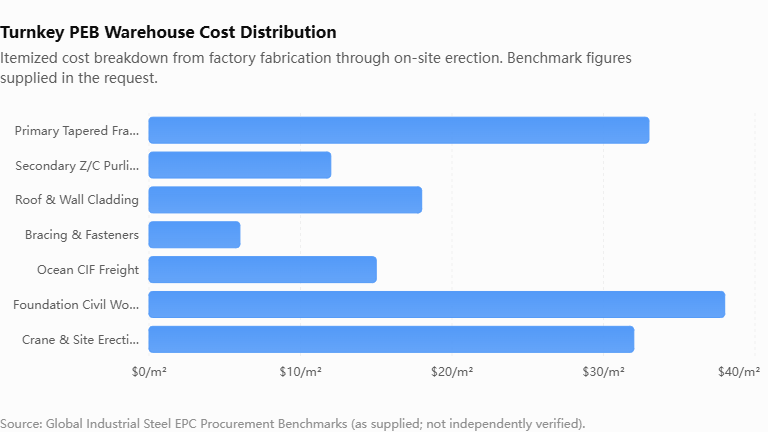
Non-Linear Span Scaling Mechanics
Clear-span geometries do not scale at a constant linear unit cost. Spans between 18 meters and 36 meters exhibit a relatively flat cost-per-square-meter curve because bending moments remain manageable within standard mill plate dimensions and typical transport envelopes. Rafter haunch depths rarely exceed 900 mm, allowing component nests that maximize high-cube shipping container payloads.
Once unobstructed spans expand into the 48-meter to 60-meter domain, the superstructure incurs a 25% to 40% cost jump per square meter. Because the maximum bending moment governs by:
spanning 60 meters quadruples rafter flexural demands compared to a 30-meter frame. Increasing clear span from 36m to 60m increases structural steel consumption from ~26 kg/m² to over 48 kg/m², driving non-linear superstructure cost escalation.
Meeting AISC 360-16 Table B4.1b local buckling criteria at these spans requires shifting web plates from 6 mm or 8 mm up to 14 mm or 16 mm, while flange plates reach thicknesses of 28 mm to 36 mm. Fabricating these massive sections demands continuous submerged arc welding (SAW) with full-penetration butt welds verified via ultrasonic testing per AWS D1.1. Heavy transport regulations and flat-rack shipping constraints compound logistics overhead, while site installation transitions from standard 25-ton truck cranes to coordinated dual-crane tandem lifts utilizing 80-ton to 130-ton mobile units.
Table 4: Clear-Span PEB Cost Breakdown Matrix: Raw FOB Fabrication vs. Turnkey Erected System
| Clear Span Configuration | Structural Steel Weight (kg/m²) | Raw FOB Fabrication (USD/m²) | Sea Freight & Logistics (USD/m²) | Civil Foundations & SOG (USD/m²) | Turnkey Erected Total (USD/m²) |
|---|---|---|---|---|---|
| 24m Span (Standard Logistics) | 20 - 24 | $45 - $55 | $8 - $14 | $30 - $45 | $120 - $145 |
| 36m Span (Distribution Hub) | 25 - 28 | $52 - $65 | $10 - $18 | $35 - $50 | $140 - $170 |
| 48m Span (Wide Clear-Span) | 34 - 39 | $68 - $78 | $15 - $24 | $42 - $60 | $170 - $205 |
| 60m Span (Aircraft / Heavy Logistics) | 48 - 56 | $82 - $98 | $22 - $35 | $50 - $75 | $210 - $250+ |
Mitigating Hidden Procurement Line Items
Contractors often encounter baseline supplier quotations that omit field installation hardware and trim packages. Accurate capital budgeting must identify these secondary items:
- Foundation anchor bolt packages: Require high-strength ASTM F1554 Grade 55 or Grade 105 anchor rods with double nuts and heavy washers, embedded to meet ACI 318-19 pullout capacities under a ±3 mm survey tolerance per AISC Design Guide 1 Section 2.3.
- Heavy rigging and site mobilization: Mobile crane hook time, telescopic boom lifts, and certified staging mats required to assemble heavy clear-span rafters on the ground before crane placement.
- Secondary trim components: Die-formed ridge caps, structural bridging, 0.6 mm eave gutters, external PVC or galvanized downspouts, closure strips, and sub-girts.
- Freight handling and de-stuffing: Demurrage fees, port clearance charges, and container de-stuffing expenses at inland project sites.
- Site touch-up protection: Protective coatings undergo marine transit abrasions. Field crews must apply two-pack epoxy zinc-rich primer (80 μm dry film thickness) over mechanical abrasions to restore the surface to factory Sa 2.5 shot-blasting standards.
Fabrication Quality Assurance: Factory Audits, AWS D1.1 Welding, and NDT Inspections
As a PEB Clear Span Portal Frame Warehouse Supplier, Shandong XinQiao enforces an engineering-driven Quality Assurance and Quality Control (QA/QC) protocol across all primary line components. Structural integrity in clear-span portal systems depends on rigid fabrication tolerances, verified material chemistry, and sound metallurgy across every built-up plate girder.
Mill Test Certificates must comply with EN 10204 3.1 verification, linking every structural plate directly to steel melt heat numbers. Receiving audits cross-reference heat numbers against physical stampings on hot-rolled coils and heavy plates (ASTM A572 Grade 50, ASTM A36, and Q355B). Testing protocols verify ladle chemical analysis (carbon equivalent CEV ≤ 0.44%), yield strength, ultimate tensile strength, and Charpy V-notch impact toughness values at 0°C or −20°C based on design ambient operating conditions.
Primary frame webs and flanges are processed using multi-torch CNC plasma and flame cutting systems with cutting tolerances held to ±0.5 mm to ensure proper fit-up geometry. Automated gantry fit-up stations align web-to-flange assemblies prior to submerged arc welding. Web-to-flange squareness and tilt follow tolerances in the AISC Code of Standard Practice (AISC 303-16). Beam camber conforms to the MBMA Low Rise Building Systems Manual.
Non-destructive testing (NDT) governs every stage of welding per AWS D1.1/D1.1M:
- Visual Testing (VT): AWS certified welding inspectors (CWI) evaluate 100% of all welds for weld profile and undercut. Inspectors also verify the joint for porosity and crater cracks.
- Ultrasonic Testing (UT): All full-penetration butt splices on primary rafter and column tension flanges require 100% Ultrasonic Testing (UT) per AWS D1.1 Table 6.1. Secondary shear splices receive a minimum of 20% UT spot inspection.
- Magnetic Particle Testing (MT): MT is executed on 100% of high-stress haunch plate junctions, crane bracket stiffeners, and sharp geometry transitions per ASTM E709.
Surface preparation must achieve Sa 2.5 near-white metal blast profile (40–75 μm anchor profile) to ensure adhesion of high-performance epoxy primers. Blast profiles are validated via replica tape testing per ASTM D4417 Method C. Dry Film Thickness (DFT) is mapped across rafters and haunches using calibrated digital magnetic thickness gauges in strict compliance with SSPC-PA 2. Base plates undergo identical DFT verification.
| Inspection Stage | Applicable Standard | Acceptance Tolerance | Verification Method |
|---|---|---|---|
| Plate Profiling | ISO 9013 Class 332 | Cutting tolerance: ±0.5 mm | CNC digital coordinate probe |
| Web-to-Flange Tilt | MBMA Section 6 | Flange tilt: max b/100 or 6 mm | Precision framing square and gauge |
| Web Camber Deviation | AISC 303-16 | Length ≤ 15m: ±3 mm; > 15m: ±5 mm | Taut-line offset laser gauge |
| Tension Flange CJP Welds | AWS D1.1 Table 6.1 | Zero planar defects or cracks | 100% Ultrasonic Testing (UT) |
| Haunch Fillet Welds | AWS D1.1 Clause 6 | No underbead cracking, porosity ≤ 2 mm | 100% Magnetic Particle Testing (MT) |
| Abrasive Blast Profile | ISO 8501-1 / ASTM D4417 | Sa 2.5 cleanliness, 40 to 75 microns | Surface profile gage and Testex tape |
| Protective Coating DFT | SSPC-PA 2 Level 3 | 80 to 120 microns primer, max +20% | Calibrated Type 2 magnetic gage |
PEB Supplier Evaluation Matrix and Engineering RFQ Technical Checklist
Selecting a qualified PEB Clear Span Portal Frame Warehouse Supplier requires shifting procurement criteria from raw material weight pricing to strict structural compliance and fabrication verification. A rigorous technical RFQ must explicitly stipulate boundary conditions, code editions (AISC 360-16 / ASCE 7-22), and purlin lap ratios rather than allowing open vendor interpretation. When RFQ documents leave connection stiffness, lateral drift thresholds (H/400 to H/200), or continuous secondary member lap configurations undefined, bidders frequently optimize tonnage at the expense of framing stability.
Engineering review teams must establish non-negotiable vetting filters before issuing bid packages:
- Fabricator Qualifications: Documented AISC Certified Building Fabricator status, ISO 3834-2 welding quality systems, and EN 1090-2 Execution Class 3 (EXC3) execution control.
- In-House Detailing Capabilities: Direct modeling execution in Tekla Structures, supported by structural analysis in SAP2000 and STAAD.Pro. BIM detailing deliverables must require clash-free LOD 400 Tekla models with complete anchor bolt placement plans before foundation concrete pours to eliminate field interference.
- Ocean Logistics and Protection: Export containerization must mandate fabricated steel transport cradles; loose break-bulk or unsecured container stuffing causes flange bending damage in up to 12% of shipments. Tapered rafters and built-up columns shipped inside 40ft High Cube containers must be nested within dedicated structural steel cradles isolated by high-density polymer spacers.
Contractual risk management requires enforceable financial instruments. EPC teams should mandate a 10% performance bond valid through final structural acceptance, alongside staggered progress payments tied directly to third-party non-destructive testing (NDT) sign-offs (ultrasonic testing per AWS D1.1 for complete-joint-penetration groove welds, magnetic particle testing for primary shear plates). Enforce liquidated damages for dimensional errors, such as shop-drilled bolt hole patterns exceeding standard tolerances or primary member straightness deviations outside AWS D1.1 limits.
Balancing upfront steel acquisition cost against 30-year lifecycle performance demands strict anti-corrosion controls. Surface preparation must achieve ISO 8501-1 Sa 2.5 via automated centrifugal shot blasting, followed by an epoxy zinc-rich primer applied to a minimum dry film thickness (DFT) of 80 μm. This specification prevents premature coating breakdown and flaking, protecting steel members against structural section loss in aggressive industrial or coastal environments.
Table 5: Supplier Technical Evaluation and RFQ Engineering Checklist
| Evaluation Category | Technical Specification & Standard | Acceptance Criteria / Tolerance | Risk Allocation & Commercial Term |
|---|---|---|---|
| Structural Engineering & Detailing | AISC 360-16, ASCE 7-22, MBMA guidelines | Tekla LOD 400 model, purlin laps ≥ 10% bay span | Approval of 3D detailing prior to steel procurement |
| Material Quality & Traceability | ASTM A992, ASTM A572 Gr 50, Q355B | Mill test certificates per EN 10204 Type 3.1 | Out-of-spec heats rejected at supplier expense |
| Automated Fabrication | AWS D1.1, EN 1090-2 EXC3 | CNC cutting ±0.5 mm, web-to-flange alignment ±1.0 mm | Backcharge for unauthorized field reaming or torch cutting |
| Weld NDT Inspection | AWS D1.1 Table 6.1, ISO 9712 Level II | 100% visual, 20% UT on CJP welds, 10% MT on stiffeners | Progress billing released only upon signed NDT dossier |
| Surface Preparation & Coating | ISO 8501-1, SSPC-Paint 20, ASTM D4541 | Sa 2.5 blast profile 40-75 μm, 80 μm primer DFT | 5-year anti-corrosion coating warranty backed by retention |
| Export Packaging & Loading | ISO 1496-1, IMO Cargo Transport Units Code | Welded transport cradles, 40ft HC container tie-downs | Transit flange bending repaired under fabricator insurance |
| Foundation Interface & Erection | AISC Design Guide 1 Section 2.3 | Anchor bolt layout ±3 mm, shop-built templates | Liquidated damages for installation downtime from misalignments |
Conclusion & Core Structural Verdict
Core Engineering Verdict
Moment-resisting haunch connections must satisfy AISC 360-16 and Design Guide 1 criteria. Foundation anchor rods must resolve lateral horizontal thrust via hairpin rebar or tie rods whenever base thrust exceeds 85 kN per footing.
Ready when you are
Clear-span industrial facilities require comprehensive load-path verification and traceable material mill certificates to guarantee structural integrity. Our licensed design engineers provide complete framing optimization, finite element analysis, and connection detailing tailored to your local snow, wind, and seismic parameters. When your design team is prepared to review anchor layouts or obtain a formal fabrication estimate, send your structural drawings to our prefab steel warehouse desk for a thorough technical review.
References & Governing Engineering Standards
Base Plate and Anchor Rod Design (Second Edition)
Fisher, J. M., & Kloiber, L. A. • American Institute of Steel Construction (2006)
Building Code Requirements for Structural Concrete (Chapter 17: Anchoring to Concrete)
American Concrete Institute (2019)
Standard Specification for Anchor Bolts, Steel, 36, 55, and 105-ksi Yield Strength
ASTM International (2020)
Code of Standard Practice for Steel Buildings and Bridges (Section 7.5: Anchor Rods and Foundation Bolting)
American Institute of Steel Construction (2022)
Eurocode 3: Design of steel structures — Part 1-8: Design of joints
European Committee for Standardization (CEN) (2005)
Eurocode 2: Design of concrete structures — Part 4: Design of fastenings for use in concrete
European Committee for Standardization (CEN) (2018)
Execution of steel structures and aluminium structures — Part 2: Technical requirements for steel structures
European Committee for Standardization (CEN) (2018)
Mechanical properties of fasteners made of carbon steel and alloy steel
International Organization for Standardization (2013)
Upstream Precision: How XinQiao Steel Eliminates Site Erection Headaches
The smoothest construction projects are those where the risk of field error is engineered out long before steel leaves the fabrication plant. When building in remote overseas destinations where specialized heavy equipment and certified rigging crews are expensive, prefabricated structural components must fit together seamlessly upon arrival.
Operating a 60,000 ㎡ heavy industrial steel manufacturing facility in Taian, China, XinQiao Steel (Shandong XinQiao Steel Structure Co., Ltd.) solves overseas assembly challenges at the fabrication source: