Temporary vs Permanent Modular Pre-Engineered Steel Bridge
Specify a modular pre-engineered steel bridge on the envelope that actually controls it: design life, AASHTO LRFD HL-93 load rating, deck dead load, coating class, abutment interface, and erection tolerances. This guide separates the temporary detour from the permanent crossing, shows what each standard really fixes, and lists the documents a buyer should hold before fabrication is released.

Bridge and heavy steel specialist: AASHTO LRFD load rating, ANSI/AISC 360 member and connection design, AWS D1.1 weld quality records, and export documentation at Jinan XinQiao Steel Structure Co., Ltd.
Table of Contents & Quick Navigation
What Is a Modular Pre-Engineered Steel Bridge?
A modular pre-engineered steel bridge is a site-specific steel bridge superstructure engineered and fabricated off-site in modules, then delivered and assembled on-site with bolted or pinned connections. The superstructure can use rolled or fabricated wide-flange beams, steel trusses, or plate girders, and each module is sized for the required span, loading, deck, finish, abutments, and site access. Pre-engineered describes the off-site engineering and fabrication process; it does not mean a universal premade span or a one-size-fits-all catalog bridge.
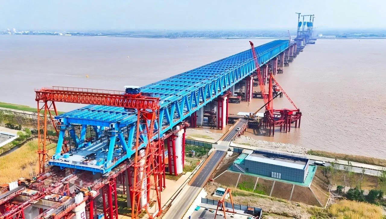
A temporary detour and a permanent crossing are design-life and specification decisions, not two separate product categories. A prefabricated modular steel bridge can be specified for either role by changing design life, coating system, deck type, and inspection plan. The owner and engineer of record must set the service life and load rating before fabrication. Member design follows ANSI/AISC 360. Vehicular load rating is project-specific to AASHTO LRFD HL-93. Structural shapes commonly follow ASTM A992/A36/A572 steel grades. Shop welding follows AWS D1.1.
Table T1. Design basis items for a modular pre-engineered steel bridge
| Design item | Required basis |
|---|---|
| Member design | ANSI/AISC 360 |
| Vehicular load rating | AASHTO LRFD HL-93, project-specific |
| Structural shapes | ASTM A992/A36/A572 |
| Shop welding | AWS D1.1 |
Procurement starts with a site survey, geotechnical data, and the required clear opening. The fabricator then produces shop drawings that fix module length, camber, splice locations, and lifting points. Transport limits and crane or excavator access can control module weight and length as much as structural capacity does. For a modular pre-engineered steel bridge, module splice plates are shop match-drilled and checked against erection drawings so field bolt-up aligns without reaming. Lifting points, bearing seats, and connection clearances are coordinated during shop detailing. Field work is limited to bolted or pinned assembly and bearing placement. Field welding is minimized by the connection design. The engineer of record remains responsible for foundation design, bearing capacity, and the final load rating. Steel grade, heat number, weld procedure specification, and coating system should be recorded per module for traceability. The term does not fix a standard width, truss depth, or deck system. Module dimensions follow transport clearances, erection equipment, and bearing seat geometry. The final specification should list the design code, load rating, steel grades, weld standard, and coating system on the shop drawings, not on a generic product sheet.
Pre-Engineered, Prefabricated, and Modular: Key Differences
Pre-engineered, prefabricated, and modular are procurement terms that fix different engineering deliverables under ANSI/AISC 360 and ASTM A6.
Table T2. Procurement terms and the engineering deliverable each one fixes
| Term | What it fixes | Procurement document | Engineering check |
|---|---|---|---|
| Pre-engineered | Off-site member design and shop detailing for a defined span, load, and site | Site-specific plan set and shop drawings | ANSI/AISC 360 member design; project load rating |
| Prefabricated | Fabrication of members and subassemblies before delivery | Shop fabrication package | ASTM A6 shape requirements; ASTM A992/A36/A572 grades; AWS D1.1 shop welding |
| Modular | Division of the superstructure into transportable and liftable units | Module schedule and match-drilled splice package | Shipping width, lift weight, field-splice location |
| Steel | Material grade and weldability | Mill certificates and heat numbers | ASTM A992/A36/A572; AWS D1.1 |
| Modular pre-engineered steel bridge | The combined delivery model: site-engineered steel superstructure fabricated as matched modules | Plan set plus module kit | All of the above, plus AISC 303-22 Section 7.13 erection tolerance |
Pre-engineered means the member design and shop detailing are completed before delivery for a defined span, load, and site. Prefabricated means the steel is cut, drilled, welded, and coated in the shop. Modular means the superstructure is divided into units that can be shipped and lifted. Steel is the material specification, not the delivery method. A modular pre-engineered steel bridge combines all four: site-specific engineering, shop fabrication, matched modules, and a specified steel grade.
Plans are site-specific engineering deliverables. They set foundation reactions, camber, bearing seats, splice locations, and the load rating. A kit is a component or module package cut to those plans. A kit is not a substitute for design. For-sale inventory must still be checked against span, load rating, deck, finish, abutments, and site conditions. An inventory bridge that fits one road may not fit another.
Module shipping width is a transport decision, not a structural standard. Typical supplier practice keeps road-shipped modules near 8 ft to 12 ft wide; wider units need oversize permits, escorts, or field splicing. Field-splice needs follow shipping length and crane or excavator reach. The erected geometry must close within AISC 303-22 Section 7.13 erection tolerances. Modular does not mean a fixed stock length. Module length, camber, and splice location are project-specific.
Temporary vs Permanent: Quick Verdict and Specification Decision
Specification verdict
The same modular pre-engineered steel bridge system can carry a temporary detour or a permanent vehicular crossing. What changes is the specification envelope, which includes design life, load rating, deck, finish and coating, abutment interface, fatigue and wind or seismic checks, inspection plan, and whether the modules will be recovered and relocated or left in service for their full design life. The owner fixes that envelope before shop drawings are released. Design life drives detail category, coating grade, and deck choice, and those items are expensive to upgrade after fabrication.
Table T3. Specification decision matrix: temporary detour versus permanent crossing
| Specification item | Temporary detour | Permanent crossing | Governing basis |
|---|---|---|---|
| Design life | Short service window stated in project requirements, from one construction season to a few years | Full structure design life set by the owner, commonly measured in decades | Owner criteria; no universal default |
| Load rating | AASHTO LRFD HL-93 or the owner's posted and legal loads, with the detour design vehicle stated | AASHTO LRFD HL-93 or owner criteria, plus long-term load combinations | AASHTO LRFD Bridge Design Specifications |
| Member design | ANSI/AISC 360-16 Chapters B through H for strength and serviceability | Same, with fatigue-sensitive details checked to ANSI/AISC 360 Appendix 3 | ANSI/AISC 360 |
| Deck | Steel grating or timber for low mass; gravel only where depth and curbs are detailed | Concrete or asphalt over deck panel with a wearing surface | Project deck specification |
| Finish | Hot-dip galvanized per ASTM A123/A123M, coating grade from Table 1 by material thickness; fasteners per ASTM A153/A153M | Galvanized plus sealer or a duplex coating system, same hardware standard | ASTM A123 / ASTM A153 |
| Abutments | Prefabricated sill on a prepared and compacted pad, recoverable | Prefabricated or cast-in-place abutments with bearing seats, scour and settlement checked | Engineer of record foundation design |
| Wind and seismic | Checked for the stated short exposure period | Full ASCE/SEI 7 wind and seismic demand for the site | ASCE/SEI 7 |
| Erection tolerance | AISC 303-22 Section 7.13 alignment limits | Same limits, plus as-built survey of bearing elevations | AISC 303 |
| Inspection | Pre-erection and post-erection visual checks, periodic while posted | Written inspection and maintenance plan with intervals set by finish | Owner bridge inspection program |
| Reuse intent | Designed for disassembly with match-marked modules and lifting points | Reuse optional; splices detailed for permanent service | Shop drawings |
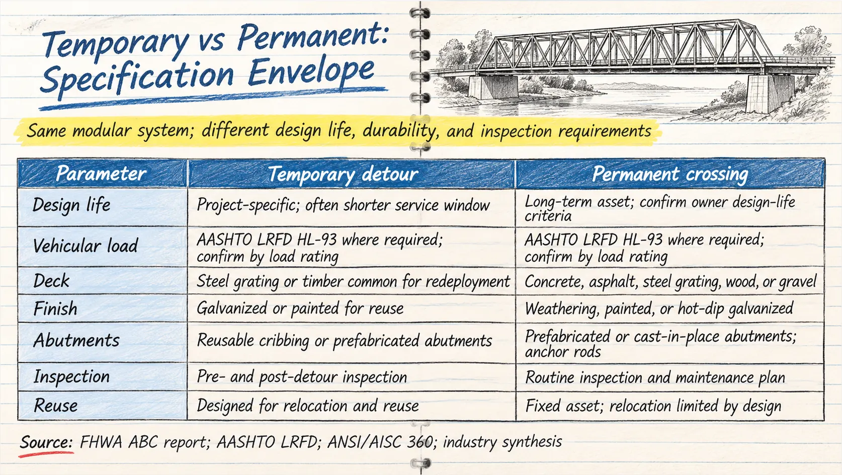
A temporary detour is still a bridge. Legal and vehicular loads require member design and a load rating to AASHTO LRFD HL-93 or the owner's criteria, and the plan set must show the rating before the structure opens to traffic. Detailing for recovery means bolted or pinned splices instead of field welds, lifting points coordinated with module weight, and a deck that can be lifted off without damaging the top flanges. Galvanizing per ASTM A123/A123M protects modules that will sit through several wet seasons and be stored between postings.
Permanent service adds a durability and fatigue case. Coating grade, drainage, and bearing detail are fixed for the life of the structure, so the finish specification needs a coating system description with surface preparation and dry film thickness recorded per module. Wind and seismic demand follow ASCE/SEI 7 for the actual site, and fatigue-prone welded details are assigned a detail category under ANSI/AISC 360 Appendix 3. Shop and field work holds to AISC 303 tolerances at the splice and bearing. The owner then adopts a written inspection plan with intervals matched to the coating system.
Installation time, price, and service life cannot be quoted as fixed values. They follow span, module size, site access, equipment, finish, and the load rating required. Set design life and load rating first, then let the specification table above drive the shop drawings.
Span and Load Capabilities by Steel Superstructure Type
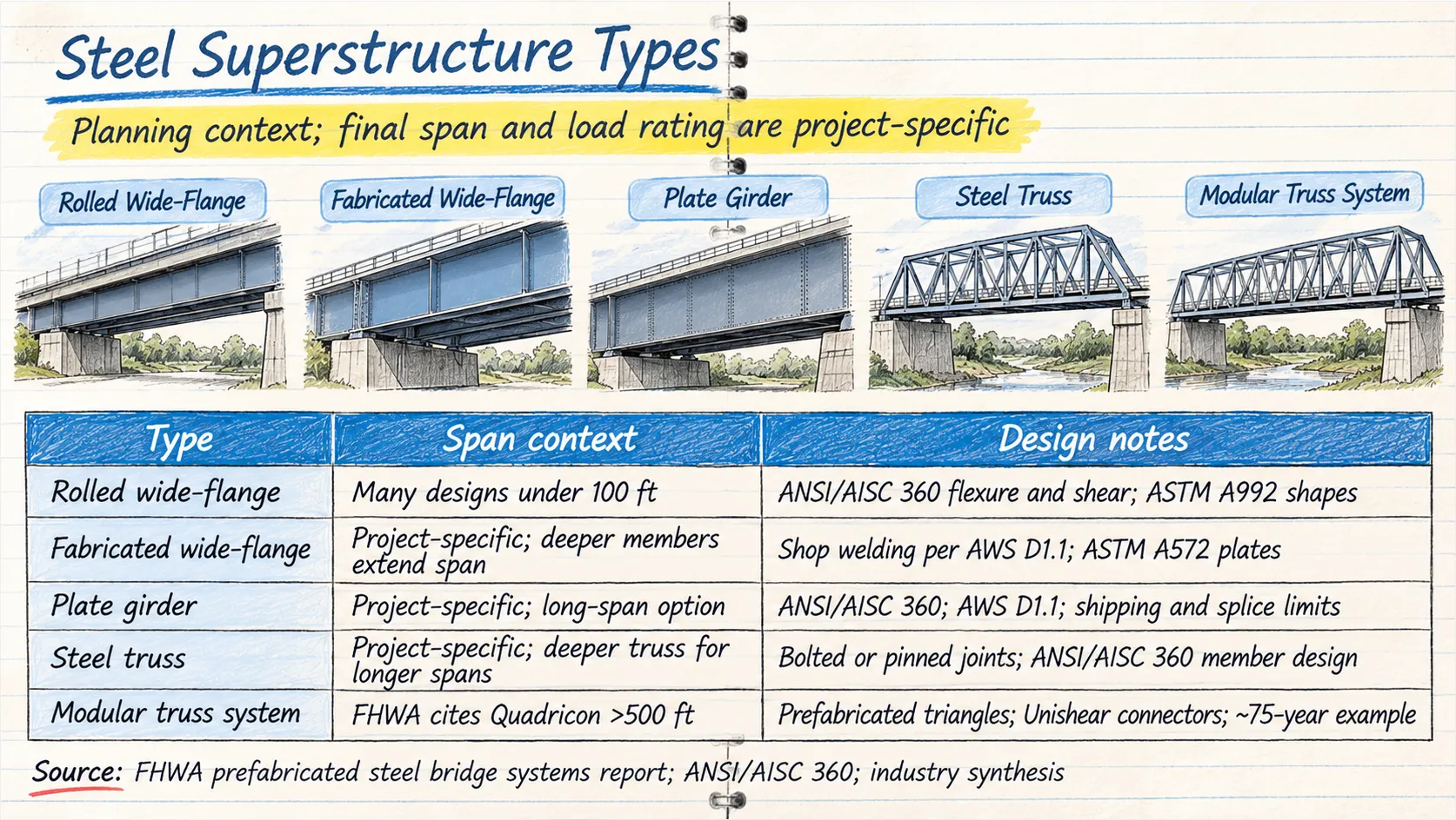
Span capability for a modular pre-engineered steel bridge is an output of ANSI/AISC 360 member design and site-specific load rating, not a fixed catalog figure. A modular pre-engineered steel bridge can be detailed for a short road crossing or an extended river crossing, and the superstructure type fixes how far the structure can reach before depth, module weight, or erection equipment takes control. The table below is a planning reference for a stated load rating, deck, and site; it is not a guarantee of capacity.
Table T4. Superstructure types for span and load planning
| Superstructure type | Typical planning span | Structural depth guide | Governing ANSI/AISC 360 checks | Bracing and detailing notes |
|---|---|---|---|---|
| Rolled wide-flange beams, ASTM A992 | Under 100 ft for many modular designs; 40 ft to 90 ft is common | Depth near span/20, limited by rolled shape availability | F2 flexure with lateral-torsional buckling from unbraced length, G2 shear, E3 compression at bearings | Cross-frames at splice points; deck or plan bracing to reduce unbraced length Lb |
| Fabricated wide-flange beams, ASTM A572 Gr. 50 or A992 plate | 80 ft to 150 ft | Span/20 to span/25 | F3 built-up flexure, G2 shear, J chapter welds per AWS D1.1 | Flange and web splices match-drilled; intermediate stiffeners where web slenderness requires |
| Plate girders, ASTM A572 Gr. 50 or Gr. 65 | 120 ft to 250 ft | Span/20 to span/25 with transverse stiffeners | F3 and F4 flexure, G2 shear including tension field action, stiffener design | Transverse stiffeners, cross-frames, and flange lateral bracing for curved or skewed layouts |
| Steel trusses, through or deck configuration | 150 ft to 400 ft | Span/10 to span/12 | E3 compression chords, D2 tension chords, gusset plate connection checks | Top chord lateral bracing, portal and sway frames at bearings |
| Proprietary modular truss, fabricated triangle modules | Extended range; published modular systems exist well beyond 100 ft | Span/10 or deeper | E3, D2, and connection design to AISC 360 chapter J with AWS D1.1 welding | Prefabricated triangle modules with corner connectors; bracing built into the module |
Member design checks that set the span
Every member in a modular pre-engineered steel bridge is checked for flexure, shear, compression, and tension under ANSI/AISC 360. Flexure follows chapter F, where the controlling limit state shifts from yielding to lateral-torsional buckling as the unbraced length of the compression flange grows. Shear follows chapter G, and web slenderness plus stiffener spacing set the capacity of deeper plate girders. Compression members follow chapter E, where effective length KL/r and slenderness govern chord and post capacity. Tension members follow chapter D, with net section and block shear checks at bolt holes. Bracing reduces the unbraced length used in chapters E and F, and it is the cheapest way to recover span capacity without adding plate thickness.
What controls the final span number
Five parameters move the number. Beam or truss depth sets the section modulus per pound of steel. Material grade sets the yield stress: ASTM A992 at 50 ksi, ASTM A36 at 36 ksi, and ASTM A572 Gr. 50 or 65 for fabricated plate. The load rating under AASHTO LRFD, commonly HL-93 for vehicular service, fixes the live load demand, and a higher rating shortens the feasible span for a given depth. Deck choice adds dead load, with concrete and asphalt heavier than steel grating or timber. Shipping length and lift weight cap module size, so a longer span may require field splices instead of a single shipped member. Welded fabrication follows AWS D1.1 with qualified procedure specifications, and rolled shapes are ordered to ASTM A992 chemistry and mechanical requirements.
Published systems provide qualified planning context. Many modular wide-flange designs serve spans under 100 ft, and proprietary truss systems built from prefabricated steel triangles and corner connectors extend well past that band. Span is a property of a specific design, not of the category: treat any published figure as planning context only, and require member design, load rating, and site-specific engineering before fabrication. Prefabricated steel truss bridges are the closest published comparison for the long-span end of that range.
Structural Loads, Load Rating, and Design Standards
A modular pre-engineered steel bridge carries load through a defined path: deck to stringers or floor beams, floor beams to the main beams or truss chords, chords to bearings, bearings to abutments or pier seats, and abutments to the foundation. Every element on that path is designed for a factored combination, not for a single nominal number. Bridge design follows AASHTO LRFD Bridge Design Specifications. Steel member and connection design follows ANSI/AISC 360. Wind and seismic criteria are checked to ASCE/SEI 7 where applicable. Shop and field welding follows AWS D1.1. Materials follow ASTM standards, typically ASTM A992 for rolled wide-flange shapes, ASTM A36 for plates and miscellaneous steel, and ASTM A572 Grade 50 or 65 for fabricated girders, with high-strength bolts to ASTM F3125.
Table T5. Governing load cases and the design basis behind each one
| Load case | Design reference | What it controls |
|---|---|---|
| Dead load (DC, DW) | AASHTO LRFD Section 3.5; steel self-weight, deck, wearing surface, railing | Beam size, camber, bearing seating |
| Vehicular live load, HL-93 | AASHTO LRFD Section 3.6.1.2; design truck or tandem plus lane load | Main member size and the load rating |
| Dynamic load allowance | AASHTO LRFD Section 3.6.2.1; 33% on truck and tandem axles, higher at deck joints | Deck, joints, and localized connection checks |
| Pedestrian live load | AASHTO LRFD Section 3.6.1.6 where a sidewalk is specified | Stringer and floor beam design under walkways |
| Wind | AASHTO LRFD Section 3.8, with ASCE/SEI 7 Chapter 26 to 30 where the owner specifies building-type exposure | Bracing, bearings, hold-down anchorage |
| Seismic | ASCE/SEI 7 seismic chapters and AASHTO LRFD seismic provisions, as directed by the engineer of record | Seat width, anchorage, ductile detailing |
| Temperature | AASHTO LRFD Section 3.12 uniform temperature range for the site | Expansion bearings, joints, module splice gaps |
| Utility, roof, and hanging loads | ASCE/SEI 7 Chapter 4 dead load provisions plus project attachment loads | Local member and connection design at attachment points |
HL-93 capability is a design output, not a catalog property. A stated HL-93 rating applies only to the span, deck, girder spacing, and steel section that the shop drawings define, and it must be confirmed by a load rating calculation to the AASHTO Manual for Bridge Evaluation using the LRFR method, with inventory and operating rating factors reported per member. A bridge detailed for a shorter span or a lighter design vehicle does not inherit an HL-93 rating by default, and a fabricator should not claim one without the rating sheet.
Roofs, utility supports, and hanging loads add eccentric mass and localized forces at their attachment points, so the connection detail and the local stiffening are checked separately from the global member design. Where fatigue applies, detail categories are checked to ANSI/AISC 360 Appendix 3, and welded details are qualified under AWS D1.1 with a written weld procedure specification. Bearing reactions, anchor rod layouts held to a field tolerance of about ±1/8 in (3 mm), and bearing seat elevations are transferred to the foundation design, which remains the responsibility of the engineer of record.
Engineering desk
Where We Can Help
Bridge procurement starts with the crossing, not the catalog. Send the span, the alignment, and the design vehicle, and our engineering desk checks module breakdown, splice locations, and the rating basis before abutment dimensions are frozen. Fabrication runs from a 60,000 sqm base with heavy H-beam assembly stations, automated submerged-arc welding bays, and CNC cutting held to plus or minus 0.5 mm. Review the steel bridge fabrication scope against your plan set.
Materials, Welded Connections, and Shop Fabrication
Material selection for a modular pre-engineered steel bridge follows the duty of each member, not a single plant-wide grade. On a bridge, main members are usually ordered to ASTM A709 Grade 50 in the toughness zone the owner's fracture-control plan requires; A992 and A572 Grade 50 are the equivalent non-bridge designations for the same strength level. Rolled wide-flange main girders are normally ordered to ASTM A992 Grade 50, plates, stiffeners, bearing assemblies, and miscellaneous steel to ASTM A36, and built-up girder webs and flanges to ASTM A572 Grade 50 or Grade 65 where higher strength or plate thickness drives the design. All rolled shapes must satisfy ASTM A6 general requirements, which set permitted variations in straightness, camber, and mass; the shop checks mill certificates and shape tolerance before layout. Anchor rods are specified to ASTM F1554 Grade 36, 55, or 105 depending on the required anchorage strength, and structural bolts to ASTM F3125 Grade A325 or A490, with tension-control F1852 assemblies where pretension is specified per ANSI/AISC 360 Table J3.2.
Table T6. Material and fabrication standard assignment by component
| Component | Governing standard | Grade or class | Shop record |
|---|---|---|---|
| Rolled wide-flange girders | ASTM A992 / ASTM A6 | Grade 50 | Mill certificate and heat number |
| Plates, stiffeners, bearing steel | ASTM A36 | Grade 36 | Mill certificate and heat number |
| Built-up girder flanges and webs | ASTM A572 | Grade 50 or 65 | Mill certificate, plate thickness check |
| High-strength bolts | ASTM F3125 | A325 or A490 | Lot certificate and rotation record |
| Anchor rods | ASTM F1554 | Grade 36, 55, or 105 | Mill certificate and tensile test |
| Member and connection design | ANSI/AISC 360 | Chapters B through J | Design calculations and shop drawings |
| Shop and field welding | AWS D1.1 | Clause 4, 5, and 8 | WPS, PQR, welder certificates, NDT reports |
| Erection tolerance | AISC 303 | Section 7.13 alignment limits | As-built survey |
Shop welding follows AWS D1.1 for every structural weld. Each welding procedure specification is supported by a procedure qualification record tested under AWS D1.1 Clause 4, and every welder is performance-qualified under Clause 5 for the process, position, and thickness range used. Inspection follows Clause 6, with visual examination on all welds and ultrasonic testing on complete joint penetration groove welds in tension splices and flange transitions. Preheat and interpass limits are held to the AWS D1.1 Table for the steel grade and thickness in use.
Fabrication tolerances are fixed before cutting. Shop capability on CNC plasma-cut plate edges and shop-drilled holes is typically within about ±0.5 mm and 1 mm of the drawing layout respectively; those are fabrication capability figures recorded on the approved shop drawing, not code limits. Erected geometry is the toleranced item, and it is governed by AISC 303 Section 7.13 alignment limits. Girder camber is set from the shop drawing rather than adjusted at fit-up. Splice plates are match-drilled against their mating module, and modules are trial-assembled on the shop floor, bolted, and checked for squareness, camber, and bearing seat elevation before match-marking and shipment.
Field work is bolt-up and pin assembly. Connections are detailed to ANSI/AISC 360 Chapter J, and erected geometry is checked against AISC 303 tolerances. Holes are aligned with drift pins, and torch-cut or reamed holes require engineer of record approval. Field welding is minimized by bolted and pinned details; where field welding is required, it follows AWS D1.1 with a field WPS, qualified welders, preheat control, and documented inspection. Deck and finish records are covered in the coating section.
Deck, Finish, and Auxiliary Options
Deck and finish selection for a modular pre-engineered steel bridge is a structural and durability decision, not a cosmetic order. Deck mass enters the dead-load case and changes member size, camber, bearing reactions, and the AASHTO LRFD load rating. Finish selection fixes surface preparation, coating build, inspection access, and maintenance cost. Auxiliary items such as back walls, sidewalks, utility supports, faux trusses, roofs, and prefabricated abutments add local loads and connection details that belong on the shop drawings.
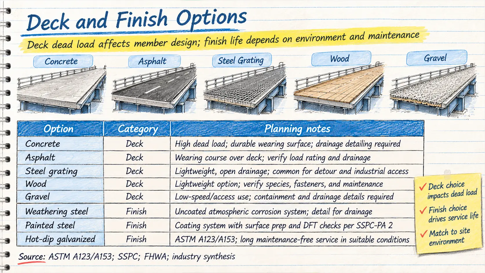
Table T7. Deck options and dead-load planning values
| Deck option | Typical build-up | Dead-load planning range | Drainage and structural effect | Typical fit |
|---|---|---|---|---|
| Concrete | 6 to 8 in reinforced slab on stay-in-place forms | 75 to 100 psf | Highest mass; sets girder size and camber; needs slope, scuppers, and sealed joints | Permanent vehicular bridges |
| Asphalt | 2 to 3 in wearing surface over concrete or steel deck | 25 to 35 psf | Adds mass over concrete; needs crown, curb, and edge drainage | Permanent crossings with concrete base |
| Steel grating | 1 to 1.5 in grating on stringers | 4 to 8 psf | Open drainage and low dead load; debris control and edge details are required | Temporary detours, industrial access |
| Wood | 3 to 4 in timber deck on joists | 8 to 12 psf | Light deck; gaps drain but joist blocking and flashing are required | Low-volume and temporary crossings |
| Gravel | 6 to 12 in compacted aggregate with geotextile | 55 to 100 psf | Mass depends on depth; needs curbs, retention, and positive drainage | Remote and low-volume roads |
Deck dead load is assigned to DC or DW under AASHTO LRFD Section 3.5. A heavier concrete or gravel deck lowers the available live-load rating unless girders, diaphragms, and bearings are sized for it. Drainage controls durability as much as coating. Ponding at a low point, trapped water at a splice plate, or a clogged scupper keeps steel wet and shortens coating life. Steel grating drains through the surface but passes debris. Concrete and asphalt need slope to scuppers or edge drains. The shop drawings should show deck attachment, stud or clip details, joint seals, and drainage paths.
Table T8. Finish systems, surface preparation, and coating build
| Finish | Surface preparation and standard | Coating build and DFT | Environment fit | Maintenance and limits |
|---|---|---|---|---|
| Weathering steel | Uncoated; SSPC-SP 6/NACE No. 3 where uniform oxide or shop primer is specified | No coating build; oxide forms with wet and dry cycles | Rural and low-chloride sites with good drainage | Inspect for pack rust at laps and crevices; poor fit in salt splash or trapped moisture |
| Painted steel | SSPC-SP 6/NACE No. 3 commercial blast; edges and welds prepared | Zinc primer plus intermediate and topcoat; total system often 8 to 12 mils DFT, measured per SSPC-PA 2 | Industrial and coastal sites with an owner maintenance program | Recoat when rust breakthrough or topcoat breakdown appears; inspection access is required |
| Hot-dip galvanized steel | Fabricated steel to ASTM A123; fasteners to ASTM A153 | Average minimum per ASTM A123 Table 1 for the governing thickness tier (3.5 mil / 89 µm on steel 3/16 in and thicker) | General exposure; duplex coating for severe chloride or abrasion | Zinc is consumed in chlorides; touch up damaged areas and inspect connections |
Coating build values in the finish table are typical shop targets. Final dry film thickness follows the project coating specification and SSPC-PA 2 measurement, with gauge readings recorded by area. Blast cleaning to SSPC-SP 6/NACE No. 3 is the common commercial blast grade for painted structural steel. A near-white blast to SSPC-SP 10/NACE No. 2 is used where the owner requires a higher-grade system. Primer, intermediate, and topcoat are applied as a system. Welds are inspected to AWS D1.1 before coating, and slag, spatter, and sharp edges are removed where welds are coated. Rolled shapes to ASTM A992/A572 and fabricated plate are prepared and recorded by heat number and coating batch.
Hot-dip galvanizing follows ASTM A123 for fabricated steel and ASTM A153 for fasteners. The coating grade depends on material thickness and environment. Galvanizing is not a paint substitute where acid or severe chloride exposure exists. A duplex system, galvanized plus paint, is used where appearance or added barrier protection is required. Weathering steel needs detailing that sheds water and avoids crevices. It is not a universal low-maintenance finish for coastal or continuously wet sites. Painted steel needs an owner with inspection and recoat capability. On a modular pre-engineered steel bridge, finish choice therefore follows the environment and the maintenance plan, not a single default.
Auxiliary options change local design. Sidewalks add pedestrian live load and railing loads. Utility supports add point loads and eccentricity. Faux trusses and roofs add wind area and attachment forces. Back walls and prefabricated abutments fix bearing seats and end drainage. Each item should appear on the shop drawings with its load path and coating.
Published supplier and industry literature on hot-dip galvanizing cites maintenance-free service well beyond 100 years in favorable exposure, and proprietary modular systems are sometimes quoted at around 75 years. Neither figure is traceable to a test standard, and both depend on exposure, coating quality, drainage, inspection, and maintenance. Treat them as planning references, not a site-specific guarantee. For a modular pre-engineered steel bridge, the specification should state surface preparation, coating standard, DFT, repair method, and inspection interval so the service-life claim can be verified.
Abutments, Foundation Interface, and Erection Tolerances
The abutment and foundation interface fixes the geometry that a modular pre-engineered steel bridge must close on site. Shop fabrication can hold member dimensions and camber, but the bridge still seats on bearing seats and anchor rods set in the foundation. For a modular pre-engineered steel bridge, the interface package includes the abutment or sill, back wall, bearing seats, anchor rods, grout bed, and survey control. Each item must be shown on the approved shop drawings and checked before modules are lifted.
Table T9. Foundation interface elements and field verification
| Interface element | Design requirement | Typical field or shop check | Governing reference |
|---|---|---|---|
| Prefabricated abutment, including proprietary systems such as SuperSill | Bearing capacity, settlement, sliding, overturning, scour, frost depth, and drainage reviewed by the engineer of record | Sill elevation, level, anchor rod template, and grout bed checked before setting modules | Project geotechnical report and foundation design |
| Cast-in-place abutment and back wall | Reinforcement, embedment, and backfill loads designed for the deck and soil pressure | Formwork dimensions, anchor rod projection, and back wall plumb checked before pour | Project structural drawings |
| Bearing seat elevation | Set from the approved plan and shop drawing, with allowance for bearings and grout | Survey elevation within about ±1/8 in (3 mm) of plan, typical contractor practice | AISC 303-22 Section 7.13 |
| Anchor rods | ASTM F1554 Grade 36, 55, or 105 selected for anchorage demand | Rod spacing, projection, plumb, thread condition, and template position checked before concrete cure | ASTM F1554; ANSI/AISC 360 |
| Structural bolts at bearings and splices | ASTM F3125 Grade A325 or A490, pretensioned where required | Lot certificate, tensioning method, and nut engagement checked against the shop drawing | ASTM F3125; ANSI/AISC 360 Table J3.2 |
| Grout bed | Non-shrink grout placed to the thickness and strength stated on the drawings | Bearing contact, full grout coverage, and cured strength checked before loading | Manufacturer data and project specification |
Survey control starts from project benchmarks outside the excavation. The contractor sets a steel anchor rod template, checks rod spacing and projection, and records as-built coordinates before the concrete pour. After cure, the survey crew records bearing seat elevations and anchor rod locations. The erector compares that survey with the approved shop drawing before module setting. AISC 303-22 Section 7.13 alignment limits govern the erected steel geometry. Member and connection design remains under ANSI/AISC 360; erection tolerance does not relax the design check.
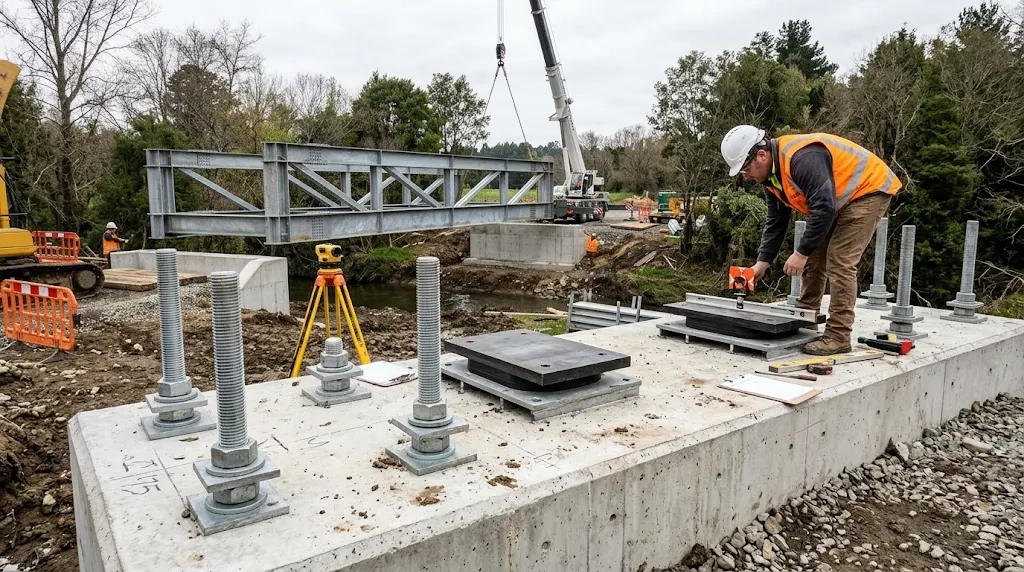
Anchor rods are inspected for straightness, thread damage, and elevation before modules arrive. Field cutting, heating, or bending anchor rods to force alignment is not permitted without the engineer of record. Grouting follows the bearing seat check. The module is set, bearing contact is verified, and non-shrink grout is placed under the base plate or sill. Anchor rod nuts are tightened after grout cure. For a modular pre-engineered steel bridge, this sequence keeps the steel geometry independent of foundation construction error.
A proprietary prefabricated abutment such as SuperSill is a supplier system, not a substitute for foundation engineering. Its use requires geotechnical review of bearing stratum, settlement, scour, sliding, frost, and drainage, plus foundation engineering review by the engineer of record. Proprietary literature supports that review. The project geotechnical report and the engineer of record govern the final abutment design.
Installation Speed, Equipment, and Site Access
A modular pre-engineered steel bridge moves the labor from the site into the shop. Site work is setting, connecting, decking, and inspecting. The schedule is driven by equipment availability, abutment readiness, and the condition of the access road, not by bolt-up. Bolted and pinned connections reduce field hours, but they do not remove the hold points that control a safe erection.
The sequence below is the standard order for a permanent or temporary crossing. Each step has a hold point that must close before the next crew moves in.
Table T10. Erection sequence, hold points, and governing reference
| Step | Field activity | Hold point before proceeding | Governing reference |
|---|---|---|---|
| 1 | Site access and staging: haul road grade, culvert capacity, turning radius, crane or excavator pad, overhead line clearance | Haul route and pad approved, delivery permits issued | Project traffic control plan |
| 2 | Abutment and foundation readiness: bearing seat elevation, anchor rod template, grout bed | Survey of seat elevations and rod locations signed off against approved shop drawings | AISC 303 Section 7.13 |
| 3 | Module delivery and match-mark check | Module tags, splice plates, and bolt lots counted against the shipping list | ASTM F3125 lot certificates |
| 4 | Setting on bearings with excavator or crane | Lift plan signed, rigging inspected, module landed within alignment limits | AISC 303 Section 7.13 |
| 5 | Bolted or pinned connections, working from the center outward | Bolt grade, hole alignment, and pretension method verified | ANSI/AISC 360 Chapter J and Table J3.2 |
| 6 | Field splice if the layout requires one | Fit-up gap, splice plate match, and camber checked | AWS D1.1 where welding is used |
| 7 | Deck placement and edge details | Deck attachment and drainage path confirmed | AASHTO LRFD Section 3.5 for the added dead load |
| 8 | Finish touch-up at damaged coating and field welds | Surface preparation and DFT checked against the coating specification | Project coating specification |
| 9 | Inspection and handover of records | As-built survey, bolt records, NDT reports, and load rating sheet filed | AASHTO MBE rating documentation |
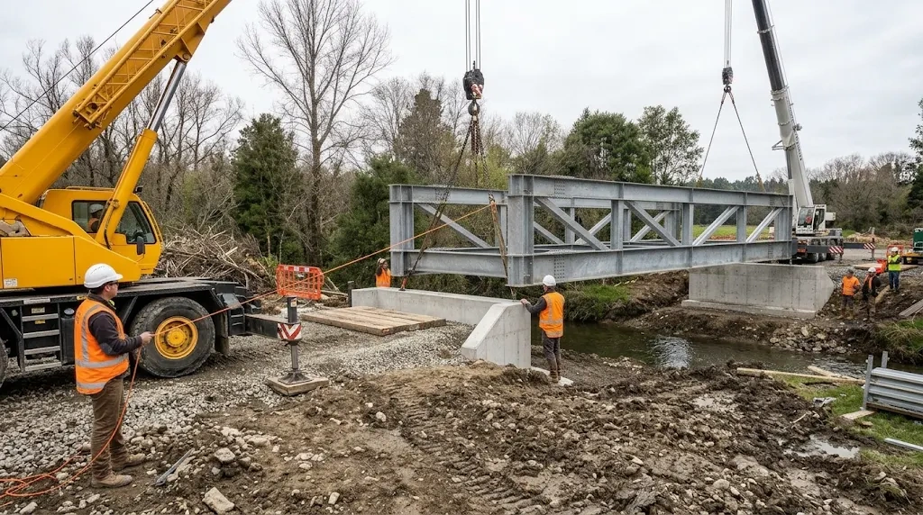
Equipment selection follows module weight, lift radius, boom reach, ground bearing pressure, and overhead clearance. Vendor planning examples commonly set modules up to about 50 ft with a single hydraulic excavator fitted with lifting eyes and a spreader bar, which suits sites where a crane cannot reach or where a crane is not on site. That is a planning example, not a rule. Longer spans, heavier deck options such as concrete, and tight or soft ground push the lift to a crane with a documented lift plan. Confirm the working load limit at the actual radius, not at the bare tip rating.
Table T11. Setting equipment by module size and site condition
| Module band | Indicative module weight (planning range) | Typical setting equipment | Access requirement | Main risk |
|---|---|---|---|---|
| Up to 50 ft, steel grating or timber deck | 5 to 15 tons | Single excavator, 8 to 15 ton class, with spreader bar | 16 ft travel lane, firm pad at both abutments | Pad bearing failure on soft ground |
| 50 to 90 ft, concrete or asphalt deck | 23 to 80 tons | Crawler crane or large excavator with boom extension | 20 ft lane, crane pad designed for outrigger pressure | Radius derating and two-point pick |
| Over 90 ft, truss or plate girder modules | 65 tons and above | Crawler or truck crane, tandem pick where required | Staging area for assembly, engineered crane pad | Reach, wind limit, and load share during tandem lift |
Planning basis: two main girders at 120 to 200 plf each, deck at 10 psf grating or timber and 75 to 100 psf concrete or asphalt, plus a 10 percent bracing and connection allowance. Each lift still needs a site-specific lift plan.
Field welding, where a splice or a bearing detail calls for it, follows AWS D1.1. The contractor uses a qualified WPS from the shop, performance-qualified welders under Clause 5, and inspection under Clause 6. Bolted connections use ASTM F3125 Grade A325 or A490 assemblies with the pretension method stated on the drawings. Erected geometry is checked against AISC 303 alignment limits, and connection design remains under ANSI/AISC 360.
There is no universal installation time for this product class. Supplier examples of assembly in a few hours apply to a stated module count, span, deck, and site, and they assume the abutments are ready and the access road is passable. Ask for a schedule broken down by step, with the equipment class and the hold points named, and compare that to the site conditions rather than to a headline number.
Durability, Inspection, and Maintenance by Finish
Durability of a modular pre-engineered steel bridge is set by four variables that interact: the finish system, the exposure environment, the deck and drainage detail, and the inspection plan that keeps the first three working. A galvanized superstructure on a well-drained concrete deck in a rural crossing behaves nothing like the same steel under a gravel deck in a chloride splash zone. Finish selection fixes the maintenance interval, and the shop drawing set must state that interval so the owner can budget for it.
Table T12. Finish systems, governing standards, and service-life expectation
| Finish | Governing standard | Shop verification | Inspection focus in service | Service-life expectation |
|---|---|---|---|---|
| Hot-dip galvanized members | ASTM A123, coating thickness by material thickness | Coating mass and thickness verified per ASTM A123 lot sampling against the Table 1 average minimum for the governing thickness tier (3.5 mil / 89 µm on steel 3/16 in and thicker) | Coating thickness gauge readings, white rust at trapped water, touch-up per ASTM A780 | Long maintenance-free service in suitable exposure; published figures above 100 years assume favorable conditions and a maintained coating |
| Hot-dip galvanized fasteners and hardware | ASTM A153 | Coating class checked against the bolt and nut specification | Thread damage, coating loss at wrench contact | Matches the connected member where the class is specified |
| Painted system | SSPC-SP 6/NACE No. 3 blast, zinc-rich primer plus intermediate and topcoat; DFT per SSPC-PA 2 | Surface profile and dry film thickness recorded at each coat, with 80 percent of readings at or above specification and no reading below 80 percent of specification | DFT spot checks, rust bloom at edges and welds, chalking and pinholing | Recoat interval depends on exposure and coating build; plan for spot repair before section loss starts |
| Weathering steel | ASTM A588 / A709 grade with weathering chemistry | Uncoated surfaces, SSPC-SP 6 where uniform oxide is specified | Pack rust at laps, crevices, and bearing seats; staining below deck joints | Good service in low-chloride sites with positive drainage; poor fit where water is trapped |
Structural welds are inspected to AWS D1.1 Clause 6, with visual examination on all structural welds and ultrasonic testing on complete joint penetration groove welds in tension splices. Bolt and erection inspection follows AISC 303 and the pretension requirements of ANSI/AISC 360 Table J3.2, with the turn-of-nut or tension-control method recorded per connection lot. Galvanized members that are field welded require zinc removal before welding and repair of the damaged zone after, and that repair is a documented hold point, not a paint touch-up.
Table T13. Inspection and maintenance planning schedule
| Interval | Activity | Reference |
|---|---|---|
| Pre-handover | Verify as-built survey, bolt pretension records, NDT reports, coating DFT log, and load rating sheet | AISC 303; AWS D1.1 Clause 6; SSPC-PA 2 |
| First year | Inspect drainage paths, deck joints, and all coating breaks; clear scuppers and debris racks | Project maintenance manual |
| Annual (routine) | Walk the superstructure for rust bloom, pack rust, loose bolts, and deck deterioration at bearings | AASHTO MBE element-level inspection practice |
| Biennial or per owner policy | Coating thickness survey on painted and galvanized surfaces; section loss measurement where corrosion is active | SSPC-PA 2 for DFT; ASTM A123 for galvanized reference values |
| After flood or debris impact | Check bearing seating, anchor rod condition, scour at abutments, and module alignment against the as-built survey | AISC 303 alignment limits |
| Recoat trigger | Spot repair when coating breakdown reaches bare steel on more than a small fraction of a member face | Coating manufacturer data sheet |
Maintenance planning checklist for the owner
- Keep the coating specification and DFT log with the as-built drawings, so a future inspector measures against the original build.
- Record bearing seat elevations and anchor rod templates at handover; alignment drift is only detectable against a baseline.
- Confirm deck drainage discharges away from steel, and that grating decks have debris control at the inlet end.
- For proprietary truss systems, any published service life of roughly 75 years is a planning figure tied to the design, environment, deck, finish, and maintenance plan. It is not a warranty, and no test standard fixes it.
- Set the inspection interval from measured coating condition after the first two cycles, not from a generic schedule.
Actual service life remains a function of design, environment, deck choice, finish, and maintenance. A galvanized bridge with blocked drainage will not reach its coating potential, and a painted bridge with an unrecorded DFT log cannot be assessed when the first rust appears.
Engineering Features and Buyer Benefits
Off-site fabrication of a modular pre-engineered steel bridge moves welding and dimensional control into a shop where AWS D1.1 Clause 4 procedure qualification, Clause 5 welder qualification, and Clause 6 inspection records are produced before shipment. The buyer receives documented weld quality and a fabrication sequence less exposed to weather and site labor availability. Schedule still depends on approved shop drawings, abutment readiness, and lifting access. Each feature below ties to a standard and to a procurement record the buyer can require.
Table T14. Engineering features tied to a standard and to procurement evidence
| Feature | Engineering basis | Buyer benefit | Procurement evidence |
|---|---|---|---|
| Shop-fabricated modules | ANSI/AISC 360 Chapter N quality control; AWS D1.1 Clause 6 inspection | Weld and dimensional defects are found before mobilization | WPS, PQR, welder certificates, NDT reports, mill certificates |
| Bolted or pinned module connections | ANSI/AISC 360 Chapter J; ASTM F3125 bolts; AISC 303 Section 7.13 alignment limits | Less field welding and fewer weather-sensitive field operations | Bolt lot certificates, pretension records, match-drilled splice plates |
| Clear-span superstructure | AASHTO LRFD Section 3 load cases; member design to ANSI/AISC 360 | Removes intermediate piers where span and rating support it, reducing foundation and channel work | Load rating sheet, foundation layout, bearing seat elevations |
| Coating system | ASTM A123/A153 galvanizing or project coating specification | Extends the service interval when drainage and exposure are controlled; maintenance can be budgeted | Coating mass and thickness records, DFT readings, touch-up records |
| Prefabricated abutments | AASHTO LRFD Section 10 foundation design and Section 11 abutment design | Simplifies the foundation interface and fixes bearing seat geometry before module delivery | Abutment design, anchor rod template, as-built survey |
Specify the rating basis, connection type, coating class, and abutment interface on the approved shop drawings. Where field welding remains, it follows AWS D1.1. Erection tolerances follow AISC 303. Coating repair follows the project coating specification. This record set lets a buyer compare bids on the same technical basis rather than on a headline span or price.
Best-Fit Use Cases and Application Considerations
A modular pre-engineered steel bridge fits where off-site fabrication, bolted or pinned assembly, and a defined foundation interface reduce site labor. The structural basis stays with the engineering sections above: AASHTO LRFD HL-93 for live load, ANSI/AISC 360 for member and connection design, ASCE/SEI 7 for wind and seismic, ASTM A123 for galvanized coating, and AISC 303 Section 7.13 for erection alignment. The table below maps common applications to the fit checks that decide whether this procurement route is appropriate. It is a screening aid, not a substitute for project-specific design.
Table T15. Application fit checks by use case
| Use case | Access and staging | Permitting and load rating | Deck and finish | Abutment and inspection |
|---|---|---|---|---|
| County roads | Confirm haul route, turning radius, and overhead clearance for module delivery | County right-of-way permit; design and rating basis to AASHTO LRFD HL-93 as required by the owner | Concrete or asphalt deck; galvanized or painted steel | Cast-in-place or prefabricated sill; inspect bearing seats and drainage paths |
| Public works and municipal projects | Urban traffic control; crane or excavator pad outside live lanes | Public bid documents; environmental permits; load rating sheet at handover | Concrete deck with sidewalk and utility supports where specified | AISC 303 alignment check; inspect anchor rods and bearing grout |
| State and national parks | Narrow access roads and limited crane reach | Environmental and cultural review; owner-specified rating basis | Wood or gravel for low-volume crossings; grating for temporary use | Weathering steel in low-chloride sites or galvanized steel; inspect for pack rust and trapped water |
| Timber harvesting roads | Unpaved haul road; seasonal staging | Forest permit; logging vehicle loads outside HL-93 require a defined project vehicle | Wood or gravel deck; galvanized finish for wet exposure | Prefabricated sill; inspect deck retention and edge details |
| Energy, mining, and industrial access | Heavy equipment access and crane reach | Site permits; mine or plant vehicle loads require project-specific load definition | Steel grating or concrete; galvanized or painted for abrasion | Check anchor rods and impact details; inspect connections and deck fixings |
| Driveways and private crossings | Small modules; light setting equipment | Local access permit; owner-specified load basis, often below HL-93 | Gravel or wood deck; galvanized finish | Prefabricated abutment; inspect coating and drainage |
| Remote sites | Long haul and limited lifting equipment; planning context only: modules up to about 50 ft are commonly set with a single excavator in typical supplier practice | Transport and environmental permits; rating basis confirmed before fabrication | Grating or wood deck; galvanized finish | Prefabricated abutment; set inspection interval before delivery |
| Temporary detours | Rapid set and removal; staging away from traffic | Temporary structure approval; detour traffic load rating | Steel grating for low dead load and open drainage | Reusable sill blocks; inspect bolted connections at each move |
For every case, confirm the deck dead load under AASHTO LRFD Section 3, the finish and inspection plan from the durability section, the abutment interface from the foundation section, and the erection hold points from the installation section. The application changes the deck, finish, abutment, and inspection plan. It does not change the design standard.
Site-Specific Design and Procurement Checklist
A modular pre-engineered steel bridge is procured on documents, not on a headline span. Two suppliers quoting the same 80 ft crossing can deliver very different structures if the load rating basis, deck dead load, finish class, and abutment interface stay open. Fix those variables before fabrication release so bids compare on the same technical basis.
Table T16. Procurement checklist for site-specific design release
| Item | Buyer input or approved document | Governing reference | Hold point |
|---|---|---|---|
| Span and geometry | Clear span, skew, profile grade, vertical clearance, module count, splice locations, camber | AASHTO LRFD Section 3; ANSI/AISC 360 | Approved shop drawing |
| Site survey and geotechnical data | Topographic survey, project benchmark, boring logs, bearing capacity, settlement, scour, frost depth | AASHTO LRFD Section 10 | Foundation design released |
| Design loads and load rating | Dead load, HL-93 live load, wind and seismic, project vehicles, permit loads | AASHTO LRFD HL-93; ASCE/SEI 7 | Load rating sheet issued at handover |
| Temporary or permanent design life | Stated service target, inspection interval, reuse plan, coating class | Project specification | Finish and deck locked |
| Deck and finish | Deck type and thickness, wearing surface, drainage path, galvanized or painted system | AASHTO LRFD Section 3.5; ASTM A123/A153 | Dead load confirmed against member design |
| Abutment and anchor rod interface | Sill or cast-in-place abutment, bearing seat elevation, rod grade and template, grout bed | ASTM F1554; AISC 303 Section 7.13 | Anchor rod survey signed off before pour |
| Erection equipment and access | Module weight, lift radius, ground bearing pressure, haul route, overhead clearance | Project lift plan and traffic control plan | Lift plan approved |
| Shop drawings | Erection marks, connection details, bolt lists, weld symbols, coating notes | AISC 303 | Written approval before cutting |
| Welding inspection | WPS, PQR, welder qualification, visual and UT coverage on complete joint penetration welds | AWS D1.1 Clause 6 | NDT reports filed |
| Coating and DFT inspection | Surface preparation, coating class, dry film thickness readings by lot | ASTM A123/A153; SSPC-PA 2 | Coating records accepted |
| Permits | Right-of-way, environmental, transport, waterway | Local and owner requirements | Permits issued before shipment |
| Engineering review | Sealed calculations, rating package, erection plan, as-built survey | ANSI/AISC 360; ASCE/SEI 7 | Final record set delivered |
Cost drivers move together, so quote them as a package rather than as a span number. The table below shows what changes the fabricated and installed cost and which design lever controls it.
Table T17. Cost drivers and the design lever that controls each one
| Cost driver | Effect on cost | Design lever |
|---|---|---|
| Span and module count | Longer spans add girder depth, plate weight, and splice count, raising weight per square foot of deck | Compare clear span against a pier option early |
| Load rating basis | HL-93 versus a defined project vehicle resizes members and the rating package | State rating vehicle and permit loads in the inquiry |
| Deck | Concrete at a 75 to 100 psf planning range versus grating at 4 to 8 psf changes girder size and camber | Match deck to traffic and drainage |
| Finish | Galvanizing adds shop cost and cuts maintenance; three-coat paint adds blast and DFT inspection hours | Set exposure class and recoat budget |
| Abutments | Prefabricated sill versus cast-in-place changes foundation scope and survey effort | Release geotechnical data before pricing |
| Access and erection | Excavator versus crane, haul route length, and permit conditions drive site hours | Confirm lift radius and pad bearing pressure |
| Engineering scope | Load rating, shop drawings, erection plan, and sealed review are separate deliverables | List deliverables in the purchase order |
Plan on anchor rod templates and bearing seats held to about ±1/8 in (3 mm) of plan under AISC 303 Section 7.13, with as-built survey recorded before modules ship. Where field welding is unavoidable, it follows AWS D1.1 and the repaired coating zone is a documented hold point.
Frequently Asked Questions
Common questions about a modular pre-engineered steel bridge cover span, load rating under AASHTO LRFD HL-93, ANSI/AISC 360 member design, deck and finish options, installation equipment, and cost drivers. Answers below are design-dependent: statements that rest on a named standard are cited, and the service-life examples are planning context rather than guarantees. Confirm the final values against the approved shop drawings and the project load rating sheet.
Table T18. FAQ topics and the governing reference behind each answer
| Question topic | Governing reference | What the reference fixes |
|---|---|---|
| Live load and rating basis | AASHTO LRFD HL-93 | Design vehicular live load and load rating format |
| Member and connection design | ANSI/AISC 360 | Strength, serviceability, bolt and weld capacity checks |
| Wind and seismic loads | ASCE/SEI 7 | Load combinations and lateral demand cases |
| Shop and field welding | AWS D1.1 | Procedure qualification, welder qualification, inspection |
| Galvanized coating | ASTM A123, ASTM A153 | Coating thickness on members and fasteners |
| Erection alignment | AISC 303 | Plumbness, elevation, and setting tolerances |
| Structural steel grade | ASTM A992, ASTM A709, ASTM A588 | Yield, tensile, and weathering chemistry |
| Anchor rods and bolts | ASTM F1554, ASTM F3125 | Anchorage and high-strength bolting grades |
What is a modular pre-engineered steel bridge?
A modular pre-engineered steel bridge is a site-specific crossing whose steel superstructure is engineered and fabricated off-site in modules, then delivered and assembled with bolted or pinned connections and minimal field welding. Pre-engineered describes the off-site engineering process. Each unit is designed to its span, deck, finish, abutment, and AASHTO LRFD HL-93 rating basis.
Does pre-engineered mean the bridge is not customized?
No. Each bridge is custom-designed for its location. Span, skew, deck mass, finish, abutment type, and rating basis change member sizes, camber, and connection details. The pre-engineered label covers shop fabrication under AWS D1.1 and ANSI/AISC 360, not a fixed catalog span. Treat any stock drawing as a starting point for site-specific design.
How fast can a modular pre-engineered steel bridge be installed?
Module setting can take a few hours on a favorable site, with total erection measured in days once abutments are ready and surveyed. Speed depends on module count, lift access, and connection type. Bolted and pinned joints cut field hours, but AISC 303 alignment checks and AWS D1.1 weld inspection remain hold points. Abutment readiness, not bolt-up, drives the schedule.
What equipment is needed to set the modules?
Standard site equipment usually suffices. Supplier practice commonly sets modules up to about 50 ft with a single hydraulic excavator using lifting eyes and a spreader bar. Longer spans, concrete decks, or soft ground move the lift to a crane with a documented lift plan. Confirm capacity at the actual radius and check ground bearing pressure before lifting.
How far can a modular pre-engineered steel bridge span?
Many modular wide-flange designs serve spans under 100 ft, while proprietary truss systems built from prefabricated triangles extend well beyond that band. Span capability is design-dependent: girder depth, deck mass, live load, and lateral stability set the limit under ANSI/AISC 360, and the rating is confirmed against AASHTO LRFD HL-93. Transport and lifting limits can bind before structural capacity does.
Can one bridge serve temporary and permanent use?
Yes, if the unit is designed and rated for both roles from the start. Temporary detour service still needs a defined vehicle load and a rating basis, and permanent service adds durability requirements for finish, deck, and drainage. Specify both service targets at procurement. AASHTO LRFD sets the rating basis, and ASTM A123 documents the galvanized coating for each use.
What load standard should the bridge be rated to?
Highway crossings are normally rated to AASHTO LRFD HL-93, confirmed by a load rating sheet issued at handover. Wind and seismic effects follow ASCE/SEI 7, and member and connection design follows ANSI/AISC 360. Logging, mine, and plant vehicles often exceed HL-93, so define those project vehicles explicitly. The owner states the required rating basis before fabrication release.
How long does a galvanized bridge last?
Industry literature reports hot-dip galvanized systems providing long maintenance-free service, with figures beyond 100 years in favorable exposure. Actual service life is design-dependent and follows coating thickness under ASTM A123, drainage, chloride exposure, and inspection interval. Galvanized fasteners to ASTM A153 complete the system. State the inspection interval on the shop drawings so the owner can budget for it.
Can I buy a bridge from plans or as a kit?
Yes, procurement from plans or as a modular kit is normal, provided the scope is site-specific. The package should include sealed calculations to ANSI/AISC 360, a load rating to AASHTO LRFD HL-93 where applicable, shop drawings to AISC 303, welding records to AWS D1.1, and coating records to ASTM A123. Compare bids on that document set, not headline span.
What drives the cost of a modular pre-engineered steel bridge?
Span and module count drive steel weight, and deck type, finish class, abutment scope, and permitting drive the rest. Longer spans add girder depth, plate weight, and splice work. Galvanizing to ASTM A123 costs more initially than a basic paint system but changes the maintenance budget. Quote the package, not a price per foot, because cost drivers move together.
Send the span, the design vehicle, and the abutment type
A modular bridge package is quoted from three inputs: span and alignment, the design vehicle and rating basis, and the abutment type you are building to. Send those with the target design life, and the reply covers module count, coating system, weld inspection regime, and the erection sequence, priced ex-factory by Jinan XinQiao Steel Structure Co., Ltd. Submit bridge alignment drawings and vehicle load specifications for a fabrication review.
References
AASHTO LRFD Bridge Design Specifications
American Association of State Highway and Transportation Officials (2020)
Specification for Structural Steel Buildings
American Institute of Steel Construction (2016)
Structural Welding Code — Steel
American Welding Society (2020)
Code of Standard Practice for Steel Buildings and Bridges (Section 7.13: Erection Tolerances)
American Institute of Steel Construction (2022)
Standard Specification for Zinc (Hot-Dip Galvanized) Coatings on Iron and Steel Products
ASTM International (2017)
Minimum Design Loads and Associated Criteria for Buildings and Other Structures
American Society of Civil Engineers (2022)
Standard Specification for General Requirements for Rolled Structural Steel Bars, Plates, Shapes, and Sheet Piling
ASTM International (2021)
Standard Specification for High Strength Structural Bolts and Assemblies, Steel and Alloy Steel, Heat Treated
ASTM International (2019)
Commercial Blast Cleaning
AMPP (formerly SSPC) (2018)
Standard Specification for Zinc Coating (Hot-Dip) on Iron and Steel Hardware
ASTM International (2016)
Standard Specification for High-Strength Low-Alloy Columbium-Vanadium Structural Steel
ASTM International (2021)
Standard Specification for Anchor Bolts, Steel, 36, 55, and 105-ksi Yield Strength
ASTM International (2020)
Measurement of Dry Coating Thickness with Magnetic Gages
AMPP (formerly SSPC) (2018)
AASHTO Manual for Bridge Evaluation
American Association of State Highway and Transportation Officials (2018)
Standard Specification for Carbon Structural Steel
ASTM International (2019)
Standard Specification for General Requirements for Rolled Structural Steel Bars, Plates, Shapes, and Sheet Piling
ASTM International (2022)
Standard Specification for High-Strength Low-Alloy Structural Steel, up to 50 ksi Minimum Yield Point, with Atmospheric Corrosion Resistance
ASTM International (2019)
Standard Specification for Structural Steel for Bridges
ASTM International (2021)
Execution of steel structures and aluminium structures — Part 2: Technical requirements for steel structures
European Committee for Standardization (CEN) (2018)
Upstream Precision: How XinQiao Steel Keeps a Rated Bridge Rated
A load rating is a calculation about a specific structure: a specific module length, a specific camber, a specific match-drilled splice, a specific coating build. Once the module leaves the shop with a drifted camber or an off-line hole, the rating no longer describes the steel on site. That is why the bridge package is controlled at the cutting line and the welding bay, before anything is loaded for transport.
Operating a 60,000 m² heavy industrial steel manufacturing facility in Taian, China, XinQiao Steel (Jinan XinQiao Steel Structure Co., Ltd.) controls the bridge build at the fabrication source: