PEB Portal Frame Anchor Bolt Detailing: AISC & ACI Standards
In pre-engineered building (PEB) design, detailing the base interface between the steel superstructure and foundation demands clear coordination across multiple structural codes. Everything begins at the column base. High axial loads combine with lateral wind suction or seismic drift to generate horizontal thrust and overturning moments. Detailing this critical boundary requires rigorous compliance with AISC Design Guide 1 for plate flexibility, ACI 318-19 Chapter 17 for concrete anchorage mechanics, and OSHA 29 CFR 1926.755 for field erection stability.

Specialist in industrial PEB detailing, AISC 360 connection design, and overseas turnkey project delivery at Shandong XinQiao Steel Structure Co., Ltd.
Table of Contents
Governing Codes and Design Specifications for PEB Base Detailing
In pre-engineered building (PEB) design, detailing the base interface between the steel superstructure and foundation demands clear coordination across multiple codes. Everything starts at the column base. High axial forces combine with lateral wind or seismic drift to generate horizontal thrust and base moments. The MBMA Metal Building Systems Manual defines standard PEB boundary conditions and horizontal thrust limits. This standard establishes whether an internal portal frame operates under a nominally pinned or moment-resisting base model.
PEB Portal Frame Base Design Interface Hierarchy
AISC Design Guide 1 & MBMA
Governs base plate flexibility, cantilever yield line mechanisms (m, n, λn'), and tension distribution across rod clusters.
OSHA 1926.755 & AISC 303-22
Mandates ≥4 anchor rods per column, 300 lbf (1.33 kN) eccentric erection stability load, and field setting tolerances (±3 mm cluster, ±6 mm grid).
ACI 318-19 Chapter 17
Concrete Capacity Design (CCD) checks: tensile breakout cone, pullout, side-face blowout, concrete pryout, and shear breakout.
To resolve these actions into the foundation, AISC Design Guide 1 (2nd Edition) sets base plate flexibility rules and anchor rod tensile distribution. It governs the plate thickness tp through cantilevered yield line mechanisms using the m, n, and λn' parameters. The engineer uses these checks to evaluate whether anchor rod tension follows rigid plate assumptions or elastic-plastic strain compatibility formulations.
PEB Column Base Physical Layering & Tolerance Architecture
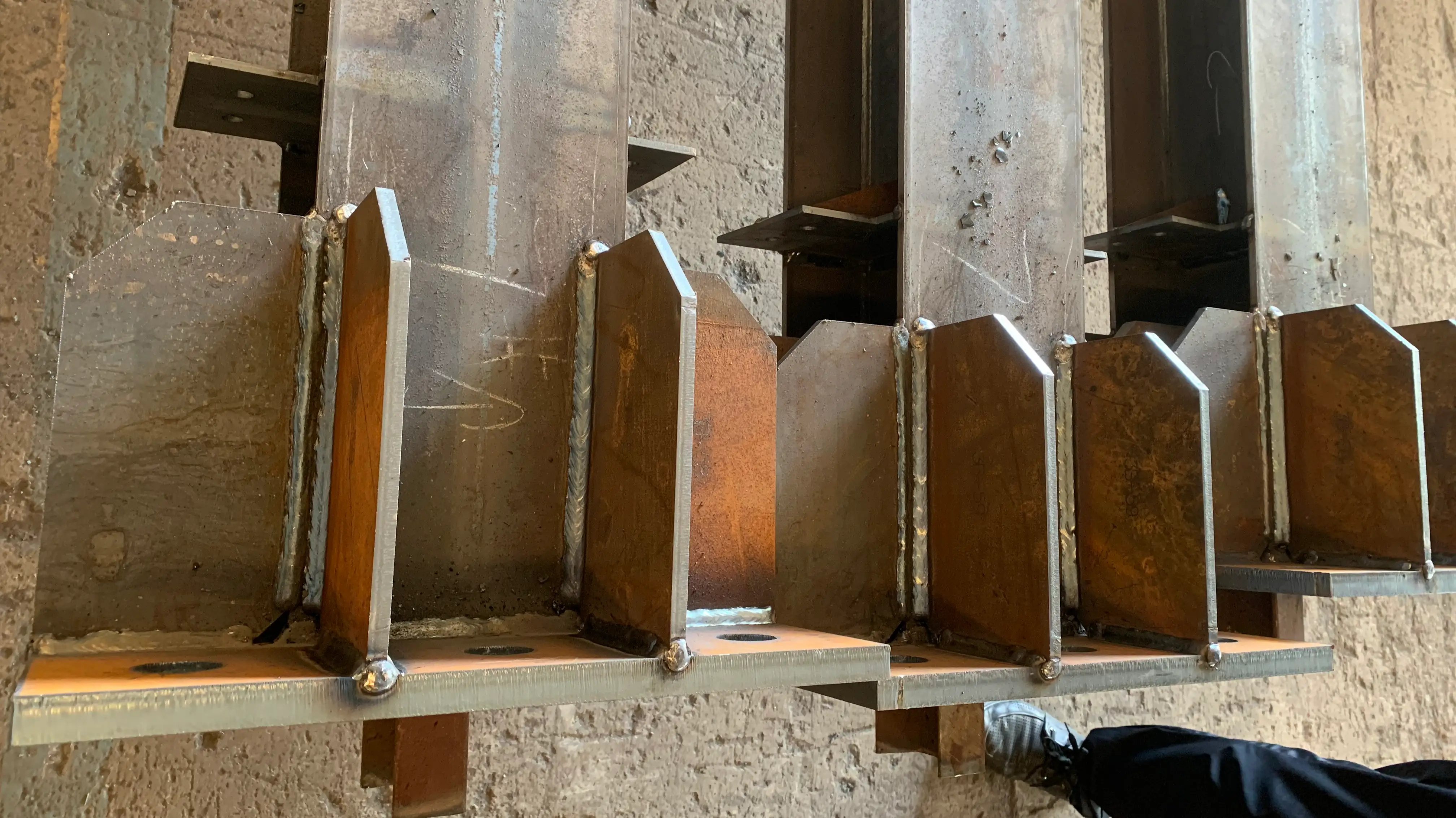
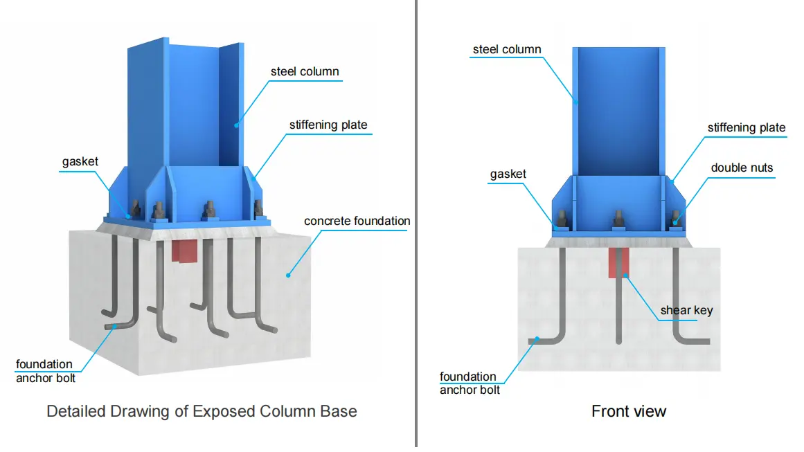
AISC DG1 / ACI 318 AlignmentWelded H-column flange transitions axial and bending forces through full-width fillets or CJP welds into base plate. Oversized holes provide erection clearance, sealed with heavy plate washers.
High-strength non-shrink grout bed (25 mm to 50 mm) elevates steel above pooling water. Below lies the reinforced pedestal with effective embedment depth hef and ACI tie confinements.
Once past the non-shrink grout bed, statutory jurisdiction shifts to concrete mechanics. Grout thickness typically runs between 25 mm and 50 mm. Below this line, ACI 318-19 Chapter 17 dictates anchorage failure modes and embedment requirements. Design checks must verify concrete breakout in tension, pullout, concrete pryout in shear, and side-face blowout for headed bolts or hooked rods (ASTM F1554 Grades 36, 55, or 105). High shear transfer often overloads the base plate interface. When friction fails, the connection requires dedicated embedded shear lugs under ACI 318-19 Section 17.11 to stop anchor rods from bending across the grout space.
Design assumptions yield to safety rules on site. Even if a structural model assumes an idealized zero-moment pinned boundary, OSHA 29 CFR 1926.755 mandates a minimum of four anchor rods per column for erection stability. Columns must withstand a minimum eccentric gravity load of 300 lbs (1.33 kN) placed at the extreme column flange tip. That mandate outlaws common two-bolt PEB base details.
Site execution must also allow for geometric tolerances in the field. AISC 303-22 Section 7.5 establishes standard placement tolerances for foundation anchor rods. It delineates the contractual boundary between the concrete contractor and the steel erector:
- • Within-group variation: ±3 mm (±1/8 in.) variation between centers of any two rods within an anchor bolt group.
- • Adjacent group variation: ±6 mm (±1/4 in.) between adjacent column group centers.
- • Grid line deviation: A non-cumulative variation along established column grid lines not to exceed ±13 mm (±1/2 in.).
| Anchor Rod Parameter | AISC 303-22 Standard Tolerance | Engineering Implications |
|---|---|---|
| Within Anchor Rod Group | ±3 mm (±1/8 in.) | Dictates clearance hole diameter in base plate to avoid torch slotted butchering. |
| Between Adjacent Group Centerlines | ±6 mm (±1/4 in.) | Governs clear bay length and longitudinal eave strut fit-up precision. |
| Cumulative Grid Line Deviation | Max ±13 mm (±1/2 in.) | Controls overall building plumbness and Crane Runway rail alignment limits. |
| Vertical Projection Elevation | ±6 mm (±1/4 in.) | Guarantees full nut thread engagement plus minimum one exposed thread pitch. |
Field variances regularly exceed shop fabrication tolerances. To handle the offset, standard PEB portal frame anchor bolt detailing implements oversized holes per AISC Design Guide 1 Table 2.3. The connection pairs these oversized holes with heavy plate washers (minimum ASTM A36 plate, 8 mm to 12 mm thick) field-welded to the base plate to reliably transmit combined horizontal shear.
Anchor Rod Material Specifications, Grades, and Component Selection
Selecting the right steel grade and matching hardware determines whether a frame survives cyclic lateral wind loads, seismic drift, and thermal swings. Anchor rods carry overturning moments, uplift reactions, and base shears directly from the column into the reinforced concrete pedestal. Base details must account for rod ductility, nut thread engagement, washer bending, and grout strength.
ASTM F1554 Material Grades and Metallurgical Constraints
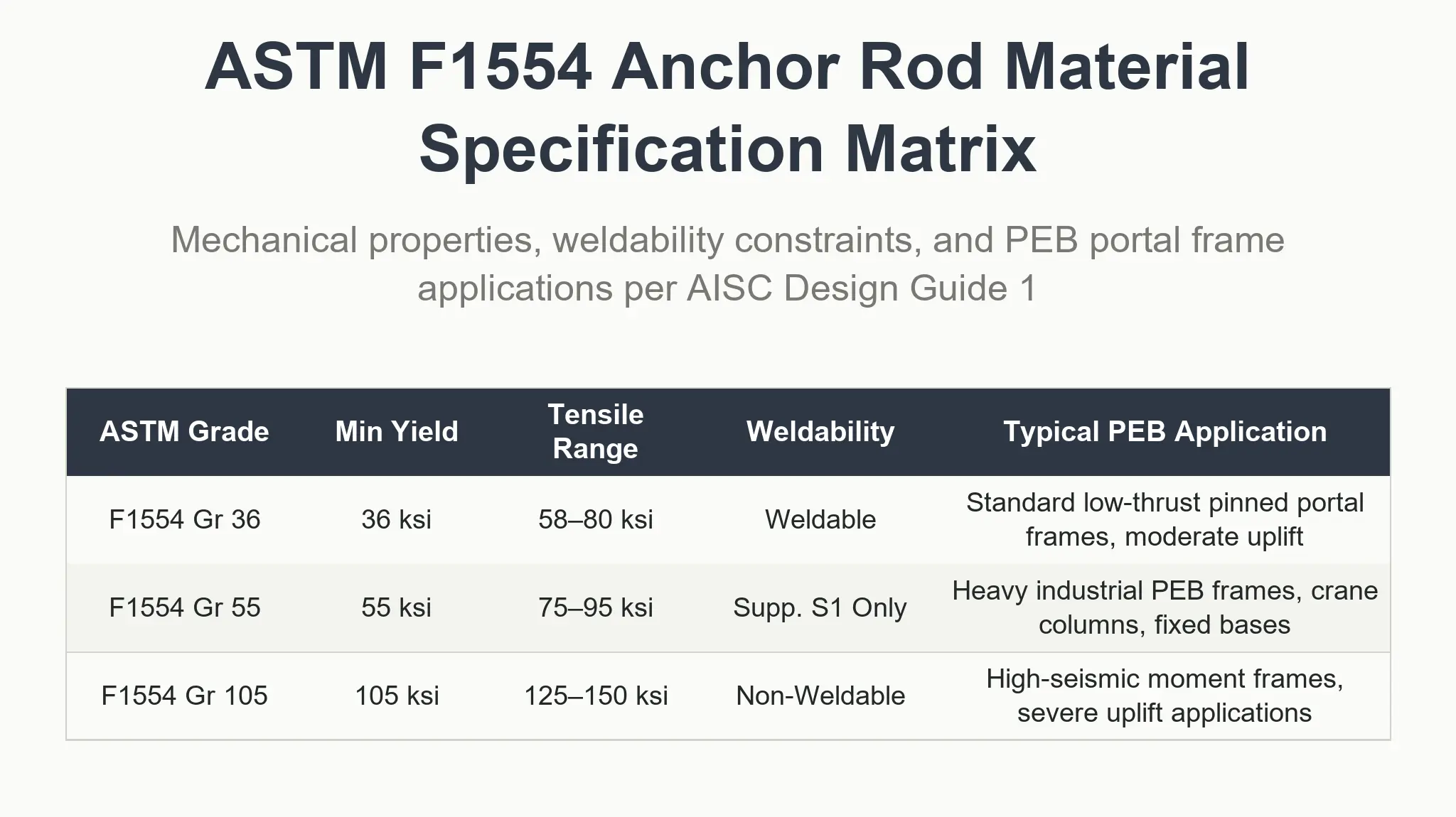
ASTM F1554 is the governing standard for structural steel anchor rods, categorized into three distinct strength grades:
-
•
Grade 36: Mild carbon steel with a nominal yield strength of Fy = 248 MPa (36 ksi), tensile strength of Fu = 400 to 550 MPa (58 to 80 ksi), and a minimum elongation of 23%. This grade offers high ductility and welds cleanly without special field preheat procedures.
-
•
Grade 55: Micro-alloyed or medium-carbon structural steel offering Fy = 380 MPa (55 ksi) and Fu = 517 to 655 MPa (75 to 95 ksi) with 21% minimum elongation. Standard Grade 55 is not weldable by default. When tack-welding to internal reinforcement templates or modifying rods on site, fabrication drawings must specify Supplementary Requirement S1. S1 restricts chemical composition to a maximum carbon equivalent (CE) of 0.45% (or C ≤ 0.30% and Mn ≤ 1.35%) per AWS D1.1.
-
•
Grade 105: Quenched and tempered alloy steel delivering high tensile capacity: Fy = 724 MPa (105 ksi), Fu = 862 to 1034 MPa (125 to 150 ksi), and a minimum elongation of 15%. ASTM F1554 Grade 105 rods must never be welded, tack-welded, hot-bent, or flame-cut under any circumstance. Heat beyond the original tempering threshold (≈ 425°C to 595°C) destroys the tempered grain structure, creating localized brittle zones vulnerable to sudden fracture under lateral wind shear or seismic uplift.
| ASTM F1554 Grade | Min. Yield Fy | Tensile Range Fu | Min. Elongation | Weldability Protocol | Standard Nut Compatibility |
|---|---|---|---|---|---|
| Grade 36 | 248 MPa (36 ksi) | 400–550 MPa | 23% | Inherently weldable | ASTM A563 Grade A Hex |
| Grade 55 | 380 MPa (55 ksi) | 517–655 MPa | 21% | Restricted: Requires Supp. S1 | ASTM A563 DH / A194 2H |
| Grade 105 | 724 MPa (105 ksi) | 862–1034 MPa | 15% | Strictly Prohibited (No Heat) | ASTM A563 DH / A194 2H |
Hardware Pairing and Washer Detailing
Hardware selection must balance proof-load capacity against rod tensile limits:
- Nut specifications: Standard ASTM A563 Grade A nuts are restricted to Grade 36 rods. For Grade 55 and Grade 105 assemblies, ASTM A563 Grade DH or ASTM A194 Grade 2H heavy hex nuts are required. Standard finished hex nuts lack sufficient thread shear area, causing thread stripping before the rod develops its full tensile rupture capacity.
- Hardened washers: Hardened steel washers conforming to ASTM F436 Type 1 sit directly below the heavy hex nut to provide a uniform bearing face and prevent galling.
- Plate washers for oversized holes: Per AISC Manual Table 14-2, base plates feature significantly oversized holes (typically nominal rod diameter db + 13 mm for db ≤ 25 mm, up to db + 25 mm for db ≥ 38 mm) to accommodate field erection tolerances of ±3 mm to ±6 mm during cage setting. Standard F436 washers will dish or pull through these openings under peak tension. Dedicated ASTM A36 plate washers bridge this gap. To resist severe flexural yield line bending across the oversized clearance gap, AISC Table 14-2 demands plate washer thicknesses of 8 mm to 12 mm, increasing to 16 mm or thicker for rod diameters exceeding 32 mm.
Grouting Media: Cementitious vs. High-Strength Epoxy
Grout transfers axial compression from the column base plate directly to the foundation concrete while elevating the steelwork clear of moisture pooling:
ASTM C1107 Cementitious Grout
Standard for industrial PEB frames. Hydraulic cement with expanding agents for volume stability in plastic and hardened states. Keep nominal bed thickness between 25 mm and 50 mm (1 to 2 inches). Thinner lifts (< 20 mm) choke flow; beds over 75 mm risk drying shrinkage cracks. Minimum compressive strength f'g ≥ 35 MPa (5,000 psi) prior to crane release.
High-Performance Epoxy Grout
Specified when frames support dynamic cyclic machinery, high-tonnage overhead bridge cranes, or chemical exposure. Delivers tensile strength above 14 MPa, compressive strength exceeding 80 MPa, and superior vibration dampening. Pours deeper than 50 mm require temperature control to prevent exothermic runaway.
Pinned vs. Fixed Column Bases: Detailing and Kinematic Behavior
In industrial pre-engineered building design, selecting and detailing the column base connection governs both frame kinematics and foundation economics. The structural engineer must balance drift limitations against the cost of substructure concrete. While a pinned base concentrates flexural demand at the rafter-to-column haunch, a fixed base distributes lateral overturning moments into concrete pedestals, reducing the required steel tonnage of the primary frame at the expense of substantial geotechnical foundation footprints.
Clustered 4-Bolt Pattern Inside Flanges
Anchor rods (ASTM F1554 Gr. 36/55) cluster tight to the column web along the weak axis. Rod pitch along the web is constrained to 100 mm–150 mm, yielding negligible internal moment lever arm. Allows rotational deformation under gravity loads without transferring moment into the foundation.
- • Base Moment: Mu ≈ 0
- • Typical Plate Thickness: 16 mm to 25 mm
- • Stiffeners: Omitted (plate flexure is desired)
- • Foundation Footprint: Compact; shear and axial loads only
Outer-Flange Wide Bolt Array & Gussets
Rods position 75 mm to 100 mm outside column flanges to establish maximum internal moment lever arm (db). Utilizes 6-to-8 bolt arrays or large-diameter (Ø36 mm to Ø48 mm) Grade 105 rods paired with full-penetration welded vertical gussets to resist frame overturning.
- • Drift Control: Restricts lateral drift to Δ ≤ H/150 or H/200
- • Typical Plate Thickness: 32 mm to 60 mm
- • Stiffeners: Vertical gusset plates aligned with flanges
- • Foundation Footprint: Substantial concrete volume & tie beams
Kinematics and Load Transfer Mechanisms
Kinematic differences between pinned and fixed conditions come down to rotational stiffness (Sj,ini). Pinned bases assume zero rotational restraint (Mu ≈ 0). They route axial compression (Pu), uplift tension (Tu), and lateral shear (Vu) straight into the concrete footing.
Fixed connections do the opposite: they preserve rotational continuity (θz → 0) to keep lateral drift within limits (Δ ≤ H/150 or H/200) during peak wind events. A fixed base resolves overturning moment (Mu) into a tension-compression couple:
This tension demand requires deep anchor embedment to engage the pedestal tie cage under ACI 318-19 Chapter 17.
Flexible vs. Rigid Base Plate Behavior (AISC Design Guide 1)
For pinned plates, AISC Design Guide 1 cantilever dimensions m and n govern base plate thickness. Sizing checks critical cantilever projections from the column profile under uniform concrete bearing pressure fp = Pu / (B · N) ≤ φc (0.85 f'c √(A2/A1)):
where l = max(m, n, λn'), with m = (N − 0.95d)/2 and n = (B − 0.8bf)/2. The resulting plate remains thin (16 mm ≤ tp ≤ 25 mm for typical frames), accommodating rotational deformation without prying failure.
In contrast, fixed base design assumes a rigid plate where plane sections remain plane during moment transfer. Under combined axial load and flexure, plate thickness escalates rapidly. Rigid fixed base plates require vertical stiffener gussets when plate bending under tension exceeds allowable limits. When calculated plate thicknesses exceed 40 mm to 50 mm, engineers introduce full-penetration welded gusset plates aligned with the column flanges. These vertical stiffeners reduce the effective cantilever span of the plate, preventing localized out-of-plane plate bending and ensuring uniform load distribution into the anchor rods.
Unintended Rotational Stiffness in Pinned Detailing
A frequent pathology in metal building engineering is detailing a "pinned" base that exhibits unintended semi-rigidity (Sj > 0.2 EIcol / Lcol). When designers widen bolt patterns toward the outer edges of the base plate or use excessively thick plates, the assembly behaves as a semi-rigid connection. This unintended rigidity transfers unexpected moment into the concrete pedestal. A nominally pinned pedestal, typically designed for concrete compressive strengths of f'c = 25 to 30 MPa and nominal reinforcing steel, is subjected to uncalculated flexural tension. This defect often manifests as horizontal shear-cracking along the cold joint at the pedestal-footing interface or diagonal tension spalling at the pedestal corners directly beneath the anchor rods.
Horizontal Shear Transfer: Interface Friction, Bolt Bearing, and Shear Lugs
Column base shear comes from portal frame thrust, wind drift, and seismic action. Detailing must transfer these lateral loads cleanly to the concrete footing. In standard PEB portal frame anchor bolt detailing, base shear transfer relies on three distinct load paths evaluated sequentially: interface friction, anchor rod bearing, and embedded shear lugs.
Tri-Tier Horizontal Shear Load Path Evaluation
ACI 318-19 & AISC DG1Governed by normal clamping force Vf = μ Pu. If uplift load combinations (0.9D + 1.0W) create net vertical tension (Nu < 0), interface friction vanishes entirely (Vf = 0).
Standard oversized holes prevent simultaneous bearing across all rods. Only 2 bolts engage unless ASTM A36 heavy plate washers (≥0.5 × db) are field-welded to the top of the base plate.
Mandatory when clear-span frame thrust exceeds rod shear capacity. A structural WT or plate welded to base underside transfers lateral shear directly into high-strength pocket concrete.
1. Interface Friction (Grout-to-Concrete Mechanics)
Interface shear resistance relies on the compressive clamping force developed at the contact plane between the column base plate, the non-shrink cementitious grout pad, and the reinforced concrete foundation. Per ACI 318-19 Section 22.9, the nominal friction capacity (Vf) is governed by:
where Pu is the factored axial compressive load perpendicular to the shear plane. Under pure gravity regimes, interface friction (μ = 0.45 to 0.55) offers an efficient primary shear transfer path. When factored load combinations such as 0.9D + 1.0W or 0.9D + 1.0E produce net vertical tension (Nu < 0), the normal clamping force vanishes across the grout interface. Consequently, Vf = 0, requiring internal mechanical anchors or shear lugs to resist the entire lateral thrust.
2. Anchor Rod Shear Bearing and Bolt Hole Kinematics
When friction is absent, lateral force shifts straight to the anchor rods. However, standard base plate fabrication introduces substantial geometric clearance. AISC Design Guide 1 permits hole diameters significantly larger than rod diameters (e.g., a 33 mm hole for an M24 rod) to accommodate typical construction placement tolerances of ±2 mm on bolt cluster patterns.
Because of these oversized holes, anchor rod bearing in oversized holes assumes only two bolts engage in shear unless heavy plate washers are field-welded to the base plate top surface. Without field welding, random hole clearance causes uneven displacement; two rods will contact the base plate edge and yield in shear long before the remaining fasteners pick up load.
To mobilize the full bolt pattern capacity:
- • Specify ASTM A36 plate washers with a minimum thickness of 0.5 × db (minimum 10 mm to 12 mm).
- • Execute field-welding of each washer to the column base plate using fillet welds designed for the allocated bolt shear force (Vu / n).
- • Restrict nominal hole clearance to 1.5 mm if using standard pre-engineered holes without welded washers.
3. Embedded Shear Lugs (Design to ACI 318-19 Section 17.11)
Structural shear lugs (WT sections or heavy plates) are mandatory when horizontal frame thrust exceeds rod shear and friction capacity, common in clear-span frames with spans exceeding 36 meters or in facilities equipped with heavy overhead bridge cranes. The shear lug typically comprises a cut structural WT (e.g., WT5×22.5 to WT8×38.5) or a heavy structural plate welded transversely to the underside of the base plate using a Complete Joint Penetration (CJP) groove weld or balanced double-fillet welds.
ACI 318-19 Section 17.11 Shear Lug Governing Equations
Nominal concrete bearing resistance of the embedded shear lug:
• f'c is the specified compressive cylinder strength of foundation concrete (min. 28 MPa to 35 MPa).
• Aslg represents the effective net projected area of the lug, deducting the grout bed thickness (tgrout, typically 25 mm to 50 mm): Aslg = blug × (hlug − tgrout).
• ψbrg,sL accounts for concrete confinement conditions (1.0 for standard edges, up to 1.4 for fully confined pedestals).
Cantilever bending moment at the base plate interface:
The plastic section modulus of the shear lug plate must satisfy φMn ≥ Mu (φ = 0.90).
Grout pockets for shear lugs require high-early-strength, non-shrink grout placement without voids. Blockouts in the concrete pedestal should provide at least 50 mm clearance on all sides of the lug. Grout formulations must achieve a minimum compressive strength of 60 MPa at 28 days and be poured with sufficient head pressure to prevent trapped air pockets beneath the base plate.
ACI 318-19 Anchorage Calculations: Concrete Breakout, Pullout, and Embedment
In clear-span pre-engineered metal buildings (PEB), wind uplift and lateral frame thrust create severe demands on foundation connections. Under high wind and seismic lateral conditions, rigid frame base plates transmit substantial axial tension (Nu) and base shear (Vu) directly into reinforced concrete pedestals. Reliable design requires applying the Concrete Capacity Design (CCD) method codified in ACI 318-19 Chapter 17. Proper execution of PEB portal frame anchor bolt detailing demands calculating all steel and concrete limit states to eliminate brittle failure modes prior to ductile yielding of the structural anchor rod steel.
1. Steel Strength in Tension (Nsa) and Shear (Vsa)
Anchor rods fabricated from ASTM F1554 (Grade 36, 55, or 105) must first be verified for pure tensile rupture and direct shear across their threaded sections:
Where Ase,N is the effective tensile stress area and futa ≤ min(1.9 fya, 860 MPa). When anchors are installed with non-shrink grout pads under base plates without built-in shear lugs, a reduction factor of 0.80 is applied per Section 17.7.1.2.1.
2. Concrete Breakout Strength in Tension (Ncbg)
Concrete breakout is modeled using an idealized 35° failure prism measured from the anchor bearing head to the concrete surface, projecting outward to a distance of 1.5 hef. Effective embedment depth hef must satisfy concrete cone breakout capacity per ACI 318-19 Section 17.6.2:
• ANco = 9 · hef2 is the base breakout area of a single anchor in deep, unconfined concrete.
• ANc is the projected failure area limited by pedestal edges (ca < 1.5 hef) and overlapping anchor cones (s < 3 hef).
• Nb = kc · λa · √f'c · hef1.5 is basic breakout strength in cracked concrete (kc = 24 for cast-in-place anchors).
3. Concrete Pullout Strength (Np)
Pullout occurs when compressive stress directly above the anchor head exceeds the bearing capacity of concrete. Heavy hex head anchors provide pullout resistance governed by the 8 · f'c · Abrg bearing threshold under ACI 318-19 Section 17.6.3:
Bearing area Abrg is limited strictly to the nut perimeter minus rod shank area. Under high wind uplift, this frequently causes pullout to govern over ductile steel yielding.
Welding thick structural plates (e.g., 100 × 100 × 20 mm ASTM A36) to the base of the rod vastly expands Abrg, eliminating pullout failure and enforcing ductile cone breakout.
4. Concrete Side-Face Blowout (Nsb)
Governs in slender pedestals where edge distance ca1 < 0.4 hef. Bursting stresses escape laterally:
For group spacing s < 6 ca1: Nsbg = [1 + s / (6 ca1)] · Nsb.
5. Concrete Pryout (Vcpg)
Deep, stiff anchor groups displace concrete behind the anchor head, failing opposite to applied shear:
Where kcp = 1.0 for hef < 65 mm, and kcp = 2.0 for hef ≥ 65 mm.
6. Combined Tension and Shear Interaction (ACI 318-19 Section 17.8)
Anchor rods under simultaneous uplift tension and lateral thrust must satisfy tri-linear or elliptical interaction limits:
7. Anchor Reinforcement Detailing: Hairpins and Ties
In PEB column pedestals with tight architectural or boundary conditions, concrete breakout cannot resist heavy seismic or cyclonic wind loads on its own. Supplementary anchor reinforcement and hairpin rebar transfer uplift and shear directly into pier longitudinal bars and the building slab system, bypassing concrete breakout limitations.
OSHA 29 CFR 1926.755 Compliance and Column Erection Stability
Erection safety precedes final service state design. Structural collapse during the initial erection phase remains a primary hazard during pre-engineered building (PEB) assembly. To mitigate unrestrained tipping hazards, OSHA 29 CFR 1926.755(a)(1) mandates that all steel columns must be secured with a minimum of four anchor rods. Within standard PEB portal frame anchor bolt detailing, this four-bolt threshold represents an absolute statutory baseline, completely outlawing the historically common practice of using two-bolt configurations for secondary framing, lean-to posts, and gable columns. A two-bolt layout creates an idealized pinned hinge along its centerline axis, possessing zero inherent rotational stiffness (kθ ≈ 0). This configuration cannot stabilize an unbraced vertical member once released from the crane hoist line.
OSHA 1926.755(a)(2) 300-Pound Eccentric Stability Formulation
Under OSHA 1926.755(a)(2), column base assemblies must withstand a 300-pound eccentric load at the column cap without collapse. That load covers dynamic forces when an ironworker climbs, connects, or ties off during steel erection. The base must resist the resulting cantilever moment without temporary guy wires:
Leveling nuts beneath the base plate must be ASTM A563 Grade DH heavy hex nuts bearing on structural F436 washers. Clear standoff distance between concrete top and leveling nut must not exceed one bolt diameter (1.0 db, typically 25 mm–50 mm) to avert Euler buckling of exposed rod shanks prior to grouting.
When columns sit on shims, packs must be leveled with full contact bearing (≥70% flat area) before hoisting to prevent rocking or edge spalling. Shims must maintain an elevation tolerance of ±2 mm, delivering a flat reference plane that prevents prying stresses in anchors.
Until non-shrink, high-strength cementitious grout (minimum compressive strength f'g ≥ 35 MPa at 24 hours, conforming to ASTM C1107) is pumped and completely consolidated beneath the base plate, the entire erection stability relies solely on the flexural rigidity of the anchor bolt cage and base plate assembly. Engineered four-bolt configurations keep PEB frames stable during erection.
Erection Tolerances, Grout Sleeves, and Field Remediation Protocols
In industrial steel construction, the geometric interface between cast-in-place concrete substructures and pre-engineered framing demands strict dimensional control. While concrete foundation construction routinely operates within coarse tolerances, structural framing requires millimeter-scale precision to avoid inducing secondary bending moments, eccentric bearing stresses, or prying actions across column baseplates. Fit-up on site demands strict anchor bolt tolerances, rigid setting templates, and clear field remediation rules.
AISC 303-22 Erection and Placement Tolerances
AISC 303-22 (Code of Standard Practice for Steel Buildings and Bridges), Section 7.5, governs the acceptable geometrical variances for anchor rod placement prior to column erection. Anchor rod groups must adhere to strict spatial boundaries relative to established building lines.
| Tolerance Parameter | AISC 303-22 Limit | Practical Field Impact |
|---|---|---|
| Centerline Offset | ±6 mm (±1/4 in.) | AISC 303-22 limits anchor rod group placement deviation to ±6 mm from established column grid centerlines. |
| Intra-Cluster Spacing | ±3 mm (±1/8 in.) | Dictates bolt-hole clearance sizing in the baseplate (AISC standard vs. oversized holes). |
| Elevation / Projection | ±6 mm (±1/4 in.) | Controls thread engagement length above leveling and clamping nuts. |
| Plumbness (Tilt) | Max 1:40 slope (1.43°) | Prevents non-uniform washer seating and localized bolt bending stress (≈25 mm/m). |
Rigid Setting Templates and Corrugated Grout Sleeves
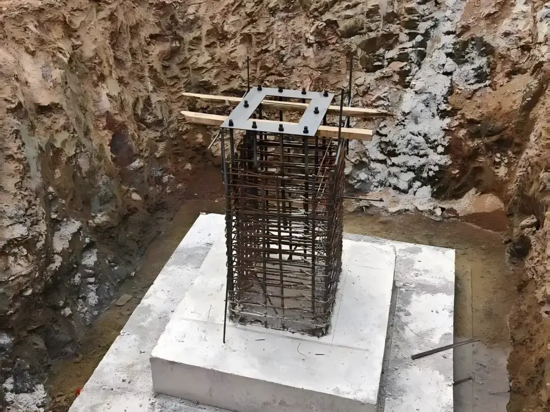
To prevent rod movement during concrete placement and vibratory compaction, anchor bolt assemblies must not be tied directly to dynamic rebar cages. Instead, clusters must be secured using rigid, reusable steel setting templates fabricated from minimum 3 mm to 5 mm carbon steel plate. These templates are CNC-machined to match baseplate bolt hole patterns, secured with top and bottom jam nuts, and cross-braced directly to the primary foundation formwork.
Corrugated Pipe Grout Sleeves for Field Adjustment
Where dynamic wind or seismic uplift does not mandate full-depth bonded embedment, engineers detail corrugated steel or HDPE grout pipe sleeves around the upper portion of the rod. Configured to an embedment depth of 6db to 8db (where db is the nominal rod diameter), corrugated pipe grout sleeves provide 25 mm to 50 mm of lateral rod ductility to accommodate casting deviations. Following final frame alignment and plumbing, these internal voids are fully consolidated using high-strength, non-shrink cementitious grout (minimum 28-day compressive strength of f'g ≥ 50 MPa).
Non-Destructive Field Remediation Protocols
When survey data indicates out-of-tolerance placement, ad-hoc torching, slotted plate butchering, or uncontrolled sledgehammer bending are prohibited. Deficiencies must be remediated per AISC Design Guide 1 (DG1) protocols:
Misaligned Rods
Cold bending is strictly limited to 1:40 slope and prohibited on ASTM F1554 Grade 105 rods. For mild Grade 36 or weldable Grade 55 rods, controlled heat-assisted bending is permissible under AWS D1.1 (rosebud torch, capped at 650°C / 1200°F, still-air cooled; water quench strictly prohibited).
Short Projection
Thread engagement must provide full nut thickness plus one exposed thread pitch. If poured low, remediate using AISC/AASHTO-compliant threaded couplers (ASTM A563 Grade DH / A194 2H) and matching threaded studs per AISC DG1 Sec. 2.11. Use beveled washers (max 1:20) for angularity.
Stripped Threads
Minor galling is dressed with a chasing die nut. If stripping exceeds two adjacent pitches within the nut grip zone, cut back below sound steel, preheat, extend via Complete Joint Penetration (CJP) butt-welding with low-hydrogen electrodes (E7018), and verify via Magnetic Particle Testing (MT).
Upstream Precision: How XinQiao Steel Eliminates Site Erection Headaches
The smoothest construction projects are those where the risk of field error is engineered out long before steel leaves the fabrication plant. When building in remote overseas destinations where specialized heavy equipment and certified rigging crews are expensive, prefabricated structural components must fit together seamlessly upon arrival.
Operating a 60,000 ㎡ heavy industrial steel manufacturing facility in Taian, China, XinQiao Steel (Shandong XinQiao Steel Structure Co., Ltd.) solves overseas assembly challenges at the fabrication source:
Governing References and Standard Specifications
Base Plate and Anchor Rod Design (Second Edition)
Fisher, J. M., & Kloiber, L. A. (2006). American Institute of Steel Construction.
Official Standard →Building Code Requirements for Structural Concrete (Chapter 17: Anchoring to Concrete)
American Concrete Institute (2019).
Official Standard →Standard Specification for Anchor Bolts, Steel, 36, 55, and 105-ksi Yield Strength
ASTM International (2020).
Official Standard →Code of Standard Practice for Steel Buildings and Bridges (Section 7.5)
American Institute of Steel Construction (2022).
Official Standard →Design of steel structures — Part 1-8: Design of joints (Section 6: Structural joints connecting H or box sections)
European Committee for Standardization (CEN) (2005).
Official Standard →