Optimized 40HQ Container Loading for Prefab Steel Buildings: Custom Dunnage, Bundling, and Volume Maximization
Optimized 40HQ container loading for prefabricated steel building components requires precise calculation of volumetric limits, payload distribution, dynamic ocean accelerations, and site erection sequences. Far from simple bulk cargo handling, loading fabricated structural steel demands advanced mechanical nesting, certified timber load-spreading grillages, and rigorous moisture micro-climate management.

Specialist in industrial PEB detailing, AISC 360 connection design, and overseas turnkey project delivery at Shandong XinQiao Steel Structure Co., Ltd.
Table of Contents & Quick Navigation
1. 40HQ Container Engineering Envelope: Volumetric Limits, Payload Thresholds, and Floor Mechanics
Stop treating an ISO 668 1AAA high-cube container like a generic bulk cargo hold. Marine export of pre-engineered steel buildings is bound by a rigid internal envelope: 12,032 mm in length, 2,352 mm in width, and 2,698 mm in height. Loading clearances are dictated strictly by the rear door aperture, limiting pass-through to 2,340 mm in clear width and 2,585 mm in clear height. Rigorous planning demands a mandatory 25 mm to 50 mm operational buffer between fabricated steel profiles and door headers to account for boom deflection, forklift mast tilt, and packaging banding clips.
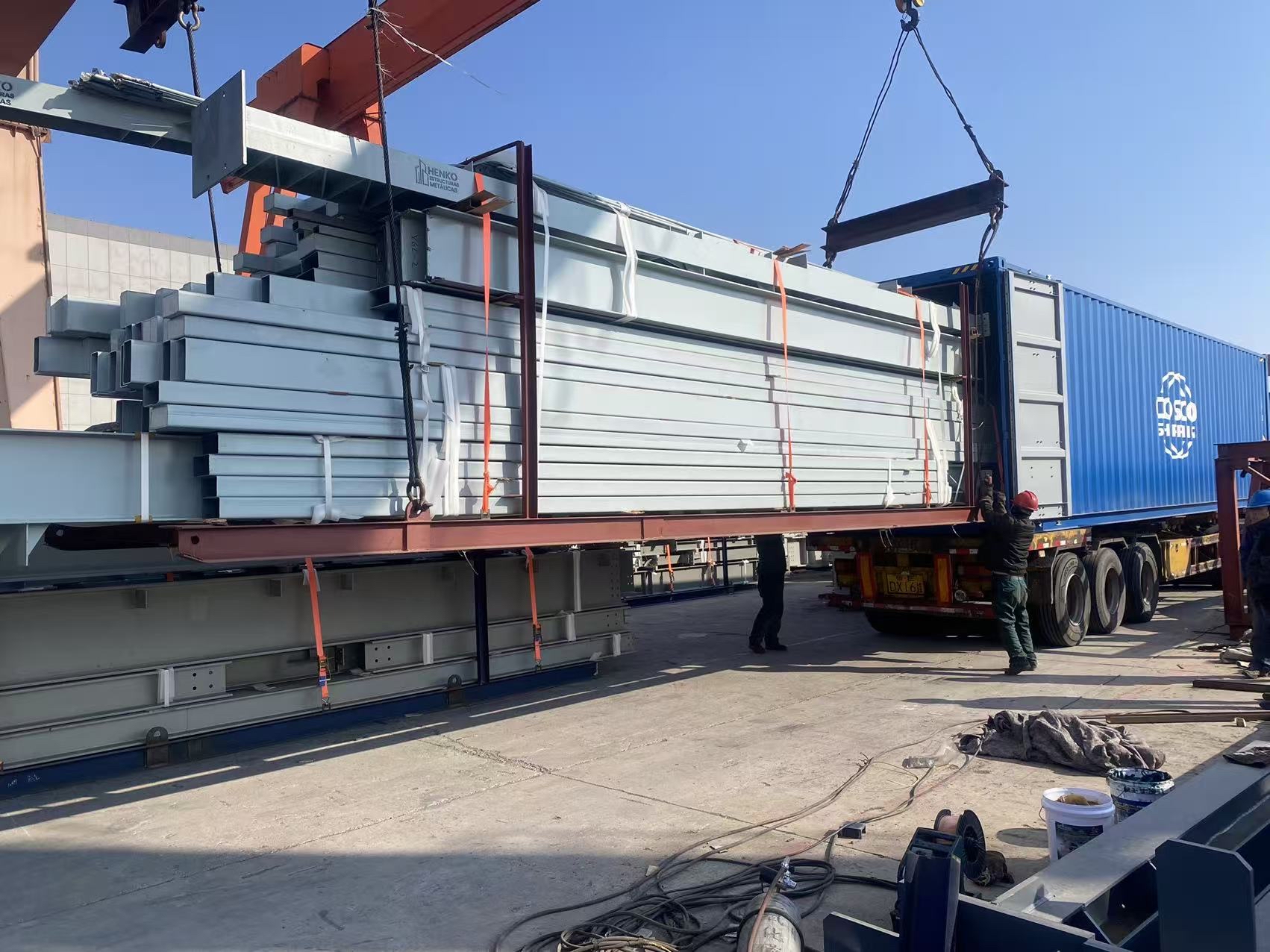
While the nominal internal volume of an ISO 1AAA container reaches 76.4 m³, the realistic effective usable volume for prefabricated structural steelwork tops out at 68.5 m³ (an effective packing density limit of approximately 89.6%). Fabricated structural elements, produced from ASTM A992 or Chinese GB/T 1591 Q355B sections under EN 1090-2 Execution Class 2 (EXC2) and EXC3 standards, feature welded moment baseplates, shear tabs, bolted haunches, and web stiffeners. Plate preparation using CNC plasma cutting maintains profile tolerances of ±0.5 mm, but protruding connection plates prevent continuous, zero-gap stacking. The resulting volumetric void spaces require engineered containment to maintain stability without sacrificing container payload capacity.
Payload distribution is controlled by the structural capacity of the container chassis and floor system. Standard ISO 1AAA containers exhibit a certified maximum gross mass of 30,480 kg. With a standard tare mass averaging 3,900 kg, the absolute payload threshold is 26,580 kg. The floor structure typically consists of 28 mm apitong or high-density laminated bamboo plywood supported by cold-formed C-channel crossmembers spaced at 300 mm to 350 mm on center. To prevent catastrophic failure of the bottom crossmembers or punch-through of the floorboards, cargo distribution must strictly comply with structural floor load limits:
- ▪ Maximum permissible running line load: ≤ 4.5 kN/m (approximately 458 kg per linear meter) along the longitudinal floor span when resting on continuous longitudinal runners.
- ▪ Concentrated axle/point loads: Per ISO 1496-1 floor testing protocols, local wheel loads must not exceed 2,730 kg over an active contact footprint of 142 cm² (standard industrial handling equipment limit).
| Engineering Parameter | ISO 668 1AAA Nominal Value | Structural Export Loading Limit | Engineering Standard / Reference |
|---|---|---|---|
| Internal Length | 12,032 mm | 11,900 mm (bundled clearance) | ISO 668 / EN 1090-2 |
| Internal Width | 2,352 mm | 2,280 mm (clear of corrugation) | ISO 668 Type 1AAA |
| Internal Height | 2,698 mm | 2,500 mm (door clearance safe line) | ISO 1496-1 |
| Door Clear Aperture (W × H) | 2,340 mm × 2,585 mm | 2,300 mm × 2,535 mm (handling envelope) | ISO 1496-1 Sec. 5.3 |
| Enclosed Gross Volume | 76.4 m³ | 68.5 m³ (effective usable volume) | XinQiao Packaging Standard |
| Maximum Gross Mass | 30,480 kg | 30,480 kg (statutory CSC plate) | IMO/ILO/UNECE CTU Code |
| Tare Weight | 3,900 kg (nominal ±2%) | 3,900 kg (actual stamped tare) | ISO 668 |
| Maximum Net Payload | 26,580 kg | 26,580 kg (subject to route limits) | Verified Gross Mass (VGM) |
| Running Line Load Limit | ≤ 4.5 kN/m | ≤ 4.5 kN/m (requires dunnage if >4.5) | ISO 1496-1 Floor Flexure |
| Point Load Limit (Floor) | 2,730 kg per 142 cm² footprint | 1,500 kg per steel bearing foot | ISO 1496-1 Sec. 6.5.2 |
| LCG Envelope Tolerance | Centerline (6,016 mm) | 6,016 mm ± 300 mm (±5% of length) | IMO CTU Code Rule 4.2.3 |
| TCG Envelope Tolerance | Centerline (1,176 mm) | 1,176 mm ± 29 mm (±2.5% of width) | EN 12195-1 / CSC Rules |
Center of Gravity (CoG) control is paramount for sea container transport safety. Packing plans must isolate the Longitudinal Center of Gravity (LCG) within ±5% of the internal length (a window of 6,016 mm ± 300 mm measured from the threshold face toward the door sill). Concurrently, the Transverse Center of Gravity (TCG) must sit within ±2.5% of the container lateral centerline (1,176 mm ± 29 mm). Failing to control these centers of gravity results in off-axis tipping moments during quayside spreader pick-up, triggering automated hoist interlocks, port-side cargo restow fees, and severe dynamic rollover hazards during tractor-trailer transit. Structural members finished with Sa 2.5 blast cleaning and 80 μm dry film thickness (DFT) epoxy zinc-rich primer must be chocked using dense timber blocking to ensure friction coefficients remain stable and CoG coordinates do not shift under marine heave and pitch accelerations.
2. Algorithmic Nesting Strategies for Tapered Rafters and Built-Up Portal Frame Columns
Non-prismatic structural profiles must be squared off into stable, rectangular modules before loading. Variable-depth portal rafters and welded H-columns (ASTM A992 or Q355B) degrade packing efficiency inside a 40-foot High Cube (12,032 mm length, 2,352 mm width, 2,698 mm height). Stacking tapered rafters in uniform orientation packs dead air, dropping shipping density below 210 kg/m³ and cubing out the container long before reaching the allowable 26,500 kg to 28,000 kg payload limit.
Base Flange: Tapering down to 420 mm at bolted field splice over 11,400 mm length.
Flange-to-web inverted placement balances aggregate cross-section across entire span.
Parallel-sided block allows 4 to 6 large rafters per bay with full rigging access.
2.1 Alternating-Taper Inversion Protocol
To neutralize trapezoidal envelope losses, fabrication facilities implement a mechanical pairing process: alternating-taper rafter nesting yields a 34.5% volumetric density increase across standard portal rafter configurations. Paired rafters are positioned flange-to-web by rotating the second member 180 degrees along its longitudinal axis. The deep haunch end (d1, typically 900 mm to 1,200 mm) nests adjacent to the shallow rafter splice end (d2, typically 350 mm to 500 mm).
Where tf is flange plate thickness and Sclear represents mechanical separation clearance (≥ 25 mm)
| Member Profile Designation | Deep End Depth (mm) | Shallow End Depth (mm) | Raw Stack Height (2 Units) | Nested Stack Height (2 Units) | Volumetric Density Gain | Primary Interlock Risk |
|---|---|---|---|---|---|---|
| PR-600/300-10 | 600 mm | 300 mm | 1,200 mm | 900 mm | 25.0% | Purlin Cleat Contact |
| PR-900/400-12 | 900 mm | 400 mm | 1,800 mm | 1,300 mm | 27.8% | Web Stiffener Clash |
| PR-1050/420-14 | 1,050 mm | 420 mm | 2,100 mm | 1,470 mm | 30.0% | Haunch Plate Binding |
| PR-1200/450-16 | 1,200 mm | 450 mm | 2,400 mm | 1,650 mm | 31.3% | Splice End-Plate Overhang |
| PR-1350/480-18 | 1,350 mm | 480 mm | 2,700 mm | 1,830 mm | 34.5% | Crane Bracket Protrusion |
2.2 Staggered Flange-to-Web Inversion Offset Calculation
Primary portal frames feature protruding welded hardware, including beam-to-column moment connection end-plates, haunch gussets, crane runway brackets, shear tabs, and cold-formed Z-purlin cleat brackets. Positioning two members directly flange-to-web without axial displacement causes rigid steel components to bind, preventing full seating and damaging protective coatings (such as Sa 2.5 blast cleaning with 80 μm dry film thickness zinc-rich epoxy primer).
The staggered flange-to-web inversion offset calculation dictates the minimal longitudinal displacement (ΔLoffset) required to clear shop-welded end-plates and haunch projections:
Where Lhaunch is haunch plate extension, tplate is end-plate thickness (25–40 mm), and Lweld_clear is weld bead buffer (≥ 25 mm)
| Welded Appendage Type | Typical Projection (mm) | Minimum Offset Margin | Dunnage Isolation Material | Fastener / Restraint System | Code Reference |
|---|---|---|---|---|---|
| Extended End-Plate | 75 to 125 mm | 25 mm | Hardwood Timber (Larch/Oak) | 32 mm Steel Banding + Corner Protectors | AISC 360-16 Table C-B4.1E |
| Haunch Gusset Stiffener | 100 to 250 mm | 30 mm | High-Density Plywood Blocks | Direct Blocking to Flange Face | AWS D1.1 Clause 5.22 |
| Purlin Cleat Bracket | 100 to 180 mm | 25 mm | Rubberized Isolation Strip | Steel Stud Retention Straps | EN 1090-2 EXC2 |
| Crane Rail Support Seat | 150 to 300 mm | 50 mm | Heavy Pine Dunnage Cradles | M16 High-Tensile Clamping Bolts | AISC Design Guide 7 Sec. 4 |
2.3 Dynamic Web Crippling and Stacking Mechanics
Ocean roll and pitch will damage poorly blocked steel framing. Per the IMO/ILO/UNECE CTU Code, multi-tier cargo stacks must be engineered for vertical dynamic accelerations reaching 1.8g (av ≈ 17.65 m/s²). When stacking tiers of tapered members inside a 40HQ, dunnage transmits upper framing weight directly onto the slender, unstiffened webs of bottom members as concentrated line loads.
Preventing web crippling under vertical dynamic acceleration requires evaluating local web compressive resistance (Pn) in accordance with AISC 360-16 Section J10.3:
Where tw = web thickness, tf = flange thickness, N = bearing dunnage length (≥ 150 mm), d = section depth, E = 205,000 MPa, Fyw = 355 MPa (Q355B)
| Stacking Configuration | Multi-Tier Height (mm) | Dynamic Load per Point | Unstiffened Web Cap. Pn | Stiffened Web Cap. Pn | Safety Factor | Web Buckling Risk |
|---|---|---|---|---|---|---|
| 2-Tier Stack (Unstiffened) | 1,470 mm | 28.5 kN | 32.1 kN | 88.4 kN | 3.10 | Low; Safe with 150mm Dunnage |
| 3-Tier Stack (Unstiffened) | 2,150 mm | 57.0 kN | 44.2 kN | 114.6 kN | 2.01 | Critical; Requires Bearing Stiffeners |
| 3-Tier Stack (Aligned Stiffener) | 2,150 mm | 57.0 kN | 44.2 kN | 162.0 kN | 2.84 | Verified Safe Under 1.8g Dynamic |
| 4-Tier Stack (Low Depth PR) | 2,450 mm | 76.5 kN | 38.6 kN | 148.2 kN | 1.93 | Failure Risk; Mandates Custom Cradles |
3. Cold-Formed Secondary Framing Bundling: C, Z, and Sigma Purlin Packaging Matrices
Cold-formed secondary steel (Z-purlins, C-sections, Sigma girts, and eave struts) consumes container volume faster than heavy structural members. Packaging operations must strap and nest these flexible, light-gauge profiles into dense, rigid bundles. Loading or flat-stacking purlins loose wastes up to three times their solid envelope volume, exhausting the container's cubic capacity long before reaching its 26.5 to 28.0 metric ton payload rating.
3.1 Nesting Geometry and Volumetric Densification
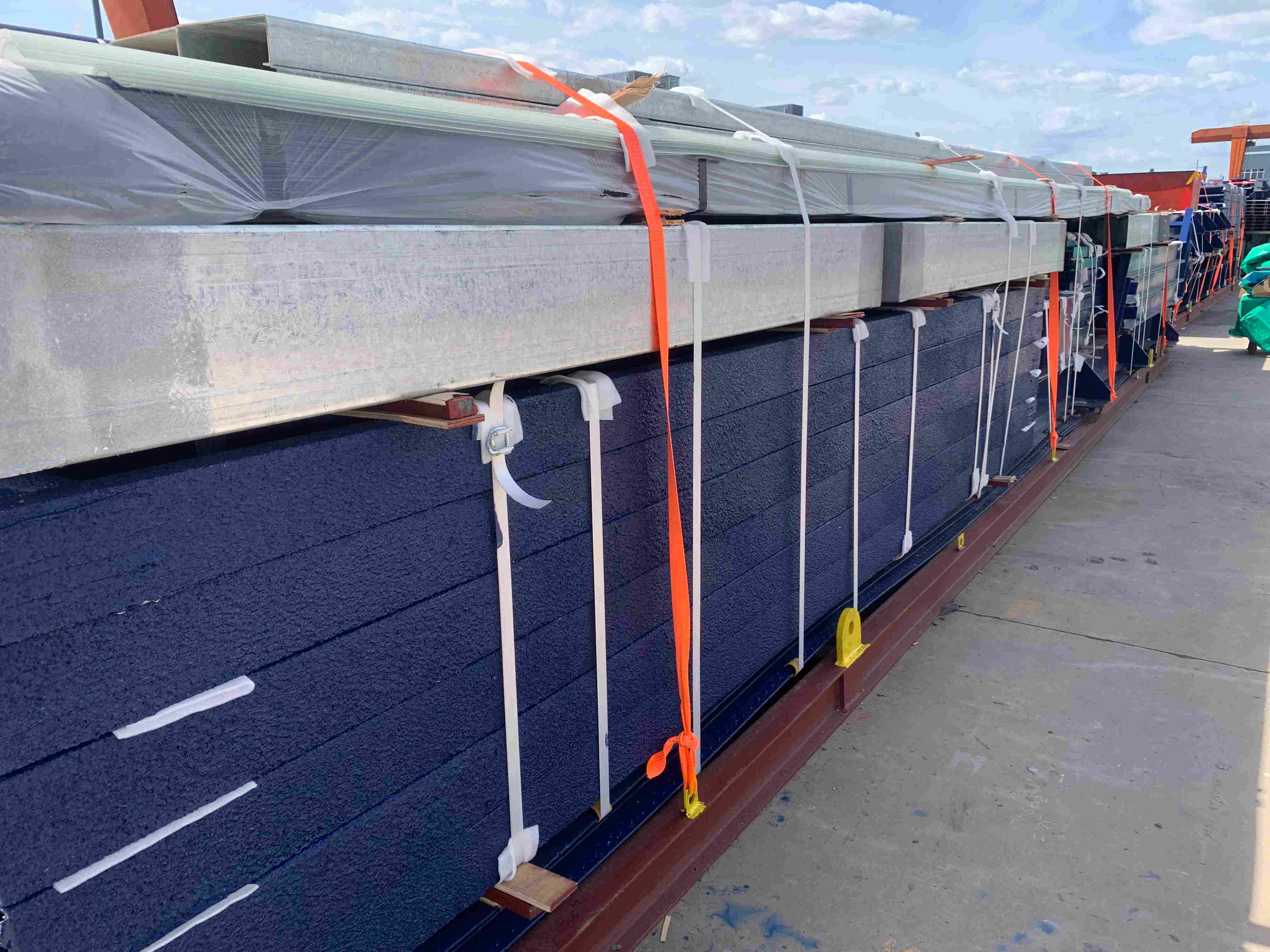
Cross-sectional profile geometry governs bundle packing efficiency. Z-sections engineered with asymmetrical flange widths (for example, a 68 mm top flange paired with a 62 mm bottom flange per EN 10162 tolerances) allow inverted web-to-web nesting. Alternating each profile top-to-bottom creates self-stabilizing rectangular blocks of 20 to 25 units per bundle. Cold-formed Z/Sigma web-to-web nesting achieves 52.0% volume reduction compared to standalone profile staging.
| Profile Designation | Depth × Flange × Lip (mm) | Thickness Range | Nesting Matrix Config | Un-Nested Vol (m³/ton) | Nested Vol (m³/ton) | Net Volume Reduction |
|---|---|---|---|---|---|---|
| Z200 Purlin | 200 × 68/62 × 20 mm | 1.8 to 2.5 mm | 4 wide × 5 high (20 pcs) | 3.42 m³ | 1.64 m³ | 52.0% |
| Z250 Purlin | 250 × 75/68 × 22 mm | 2.0 to 3.0 mm | 5 wide × 5 high (25 pcs) | 3.18 m³ | 1.55 m³ | 51.3% |
| C200 Girt | 200 × 70 × 20 mm | 1.8 to 2.5 mm | 2 × 10 opposed (20 pcs) | 3.55 m³ | 1.88 m³ | 47.0% |
| Sigma 240 Girt | 240 × 70 × 20 mm | 2.0 to 3.2 mm | 4 wide × 5 high (20 pcs) | 3.25 m³ | 1.60 m³ | 50.8% |
| Eave Strut (C-Type) | 220 × 90 × 25 mm | 2.5 to 3.5 mm | 2 × 6 opposed (12 pcs) | 2.90 m³ | 1.68 m³ | 42.1% |
3.2 Strapping Mechanics and Galvanic Coating Integrity
Bundle integrity depends on systematic pretensioning. Packaging standards require ASTM D3953 Type 1 heavy-duty high-tensile (32 mm × 0.8 mm) zinc-coated steel bands, paired with closed-seal crimp joints achieving a joint efficiency rating above 85%. Pneumatic tensioners must apply a minimum strapping pretension of 12,000 N per band. Straps must be placed at 1,200 mm to 1,500 mm on-center spacings, with double strapping deployed 300 mm from bundle ends to suppress end-splay caused by maritime dynamic pitching.
Light-gauge framing relies on thin protective layers, typically Z275 hot-dip galvanizing (275 g/m² zinc) or AZ150 55% aluminum-zinc alloy coatings per ASTM A653 or ASTM A792. High-tension strapping generates localized contact stresses exceeding 350 MPa at profile corners, which can shear these metallic barriers and initiate rust.
Protection of Z275 / AZ150 protective coatings using edge-radiused corner protectors is mandatory. These protectors are manufactured from 1.6 mm galvanized steel sheet with an inside bend radius of at least 3.0 mm. They distribute the 12,000 N clamping load across a 100 mm span, preventing notch damage, flange deformation, and premature corrosion.
3.3 De-Nesting Safety Protocols and Field Clearances
Tightly nested purlin blocks retain elastic clamping strain. Uncontrolled cutting of high-tensile bands can induce violent kinetic whip or pinch failures. Jobsite crews must observe strict de-nesting safety protocols:
- 1. Pre-Release Clamping: Master bundles must sit level on wood sleepers. Before severing the ASTM D3953 bands, install two top-mounted screw-clamp retainers over the bundle center.
- 2. Sequential Severing: Cut bands progressively from the bundle ends inward toward the center clamps, standing clear of the band rebound arc.
- 3. Mechanical Separation: Never pry cold-formed profiles apart with structural crowbars, which dent flanges and tear zinc coatings. Insert non-marring UHMW polyethylene or hardwood wedges into the profile lips to release internal vacuum without damaging factory roll-formed tolerances.
4. Custom ISPM-15 Engineered Dunnage, Saddle Design, and Line-Load Spreading Architecture
Without an engineered load-transfer path from the steel to the container floor, transit dynamics can damage both cargo and container. Delivering an engineered 40HQ container loading program for prefab steel buildings requires timber grillage and isolation assemblies designed to withstand vertical pitch, lateral roll, and longitudinal shunts under the IMO/ILO/UNECE CTU Code.
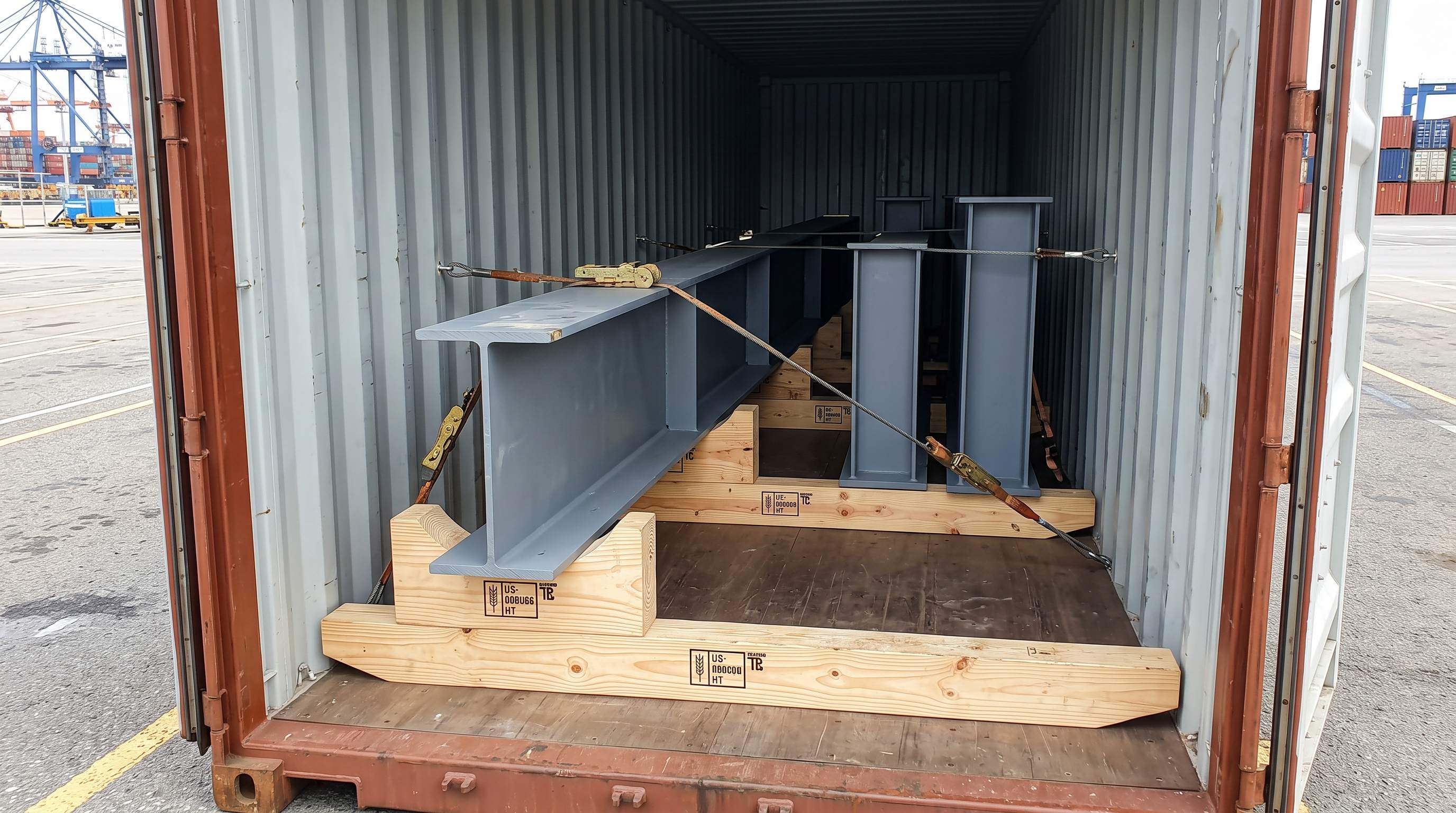
4.1 Phytosanitary Standards and Timber Selection
Untreated timber presents biosecurity risks and introduces uncalibrated moisture into the maritime envelope. Export regulations require full ISPM-15 compliance: Heat Treatment (HT) at 56°C core temperature for ≥ 30 minutes, debarked, and dried to moisture content < 18%. Kiln-drying below 18% prevents moisture transpiration inside sealed high-cube shipping containers, eliminating condensation cycles that cause coating blistering, pack rust, or micro-cracking on exposed steel surfaces. Raw timber is selected from dense structural hardwoods, specifically European Beech (Fagus sylvatica) or White Oak (Quercus alba), offering parallel-to-grain compressive strengths exceeding 45 MPa.
4.2 Container Crossmember Load Transfer Mechanics
Standard 40HQ marine containers use a 28 mm thick, 19-ply hardwood plywood floor supported by transverse cold-formed steel C-channel crossmembers (typically C120 × 45 × 4.0 mm) spaced on 300 mm to 350 mm centers. Direct point loading from thick-flanged columns (such as ASTM A992 or Chinese GB Q355B built-up H-sections) will cause punch-through failure or localized plastic deformation of the timber floorboard if concentrated between the hidden steel crossmembers.
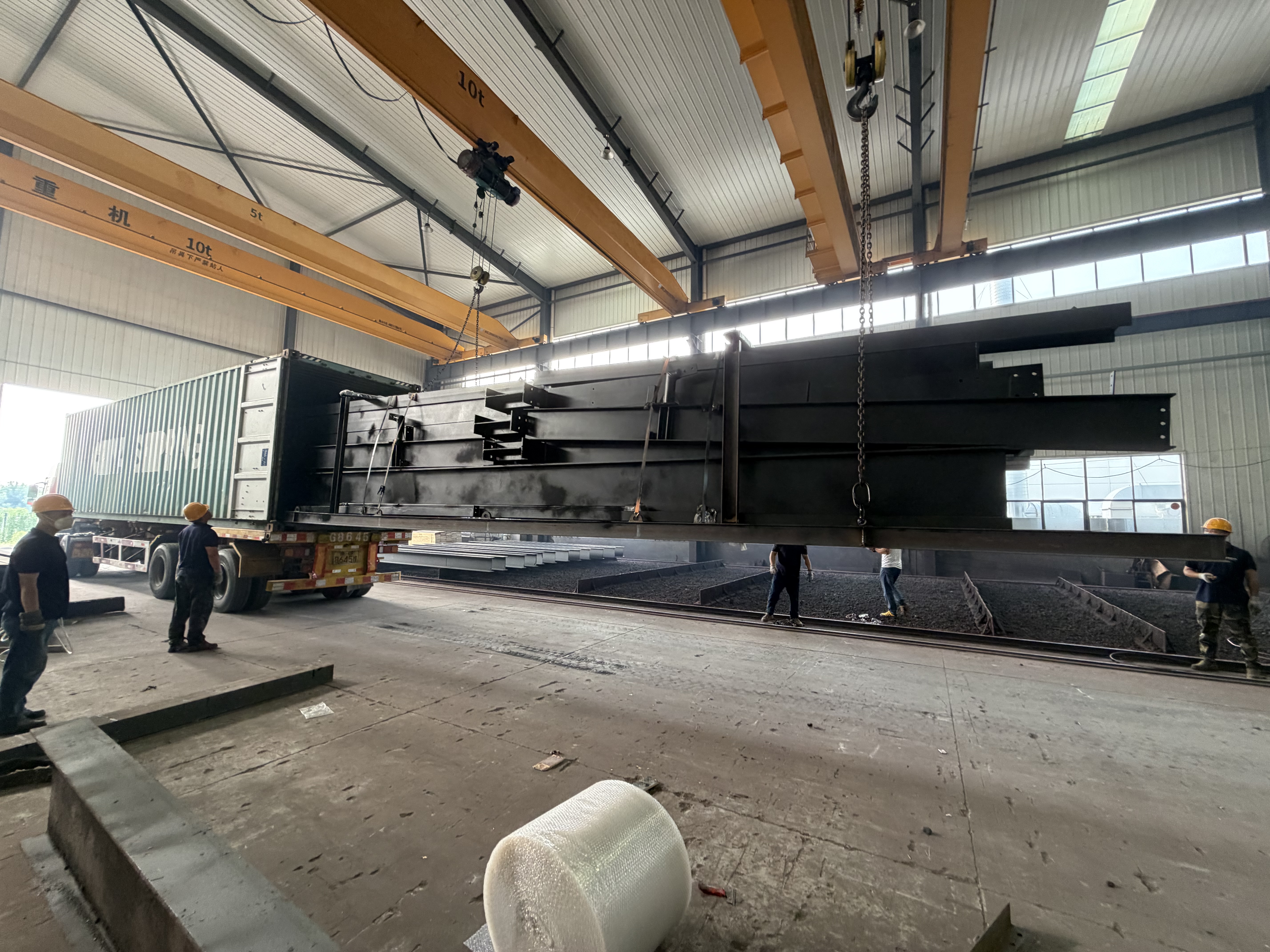
To eliminate point shear, the structural interface relies on 100 mm × 100 mm continuous longitudinal spreader runners. Aligning these runners along the container floor bridges heavy loads across a minimum of three transverse floor crossmembers at any contact point. This redistributes concentrated flange loads into broad line loads that remain well below the 4.5 kN/m limit and the 2,720 kg axle load rating dictated by ISO 1496-1.
| Dunnage Component | Nominal Dimensions (mm) | Material Specification | Structural Function | Max Design Metric |
|---|---|---|---|---|
| Longitudinal Spreader Runners | 100 × 100 continuous | Kiln-Dried Oak / Larch (ISPM-15) | Floor crossmember load bridging | ≤ 4.5 kN/m line load |
| Contoured Saddle Blocks | 150 × 75 CNC-profiled | Hardwood Beech (ISPM-15) | Rafter web and flange cradle | 65 kN static bearing per saddle |
| Vertical Tier Spacers | 50 × 100 vertical | Structural SPF Timber (ISPM-15) | Flange-to-flange tier separation | 30 kN clamping compression |
| Anti-Fretting Pads | 5 t × 100 w | Vulcanized Neoprene (Shore A 65) | Coating barrier & vibration damper | Dynamic friction μ ≥ 0.45 |
| Lateral Chock Wedges | 100 × 100 × 200 beveled | Structural Hardwood (ISPM-15) | Side wall roll restraint | 15 kN dynamic lateral thrust |
4.3 Saddle Blocks and Member Profile Geometry
Variable-depth structural rafters present unique packaging challenges. Placing tapered flanges directly on flat blocking generates single-point contact at the rafter taper inflection, creating high stress concentrations and unconstrained lateral movement.
To resolve this, processing shops cut 150 mm × 75 mm routed timber saddle blocks matching the member taper profile using 3-axis CNC timber routers driven by DXF files from Tekla structural models. These profiles match portal frame slopes (typically 1:10 or 1:12) within a shop tolerance of ±1.0 mm. Between stacked steel levels, 50 mm × 100 mm vertical separators isolate intermediate tiers. Strapped with high-tensile 32 mm × 0.8 mm cold-rolled steel bands tensioned to 8.5 kN, the entire bundle acts as a rigid, monolithic load block that prevents beam-to-beam contact during transit.
4.4 Steel-to-Steel Isolation and Coating Preservation
Ocean voyages induce continuous micro-vibrations that can damage exterior coating systems. High-exposure marine specifications require ISO 12944 C3 to C5 systems: Sa 2.5 blast profiles with 80 μm DFT epoxy zinc-rich primer, 160 μm high-build epoxy intermediate, and 60 μm polyurethane topcoat. Metal-on-metal or unpadded timber contact under vibration causes abrasive chafing that breaks the barrier film, leading to localized corrosion.
Installing 5 mm vulcanized neoprene (Shore A 65) and HDPE anti-fretting isolation barriers at all contact points absorbs low-amplitude kinetic shocks without extruding under heavy flange compression. High-density polyethylene (HDPE) buffers are mechanically fastened at rub points where sliding motion might occur during stuffing or de-stuffing, preserving the 300 μm total coating dry film thickness.
5. IMO/ILO/UNECE CTU Code Dynamic Restraint Calculations and Multi-Axis Cargo Securing
Structural calculations for 40HQ container loading cannot end at the shop gate. Fabricated Q355B and ASTM A992 built-up crane girders and columns act as rigid point loads inside a 40-foot high-cube container, subjecting framing to severe multi-axis dynamic forces governed by the IMO/ILO/UNECE Code of Practice for Packing of Cargo Transport Units (CTU Code).
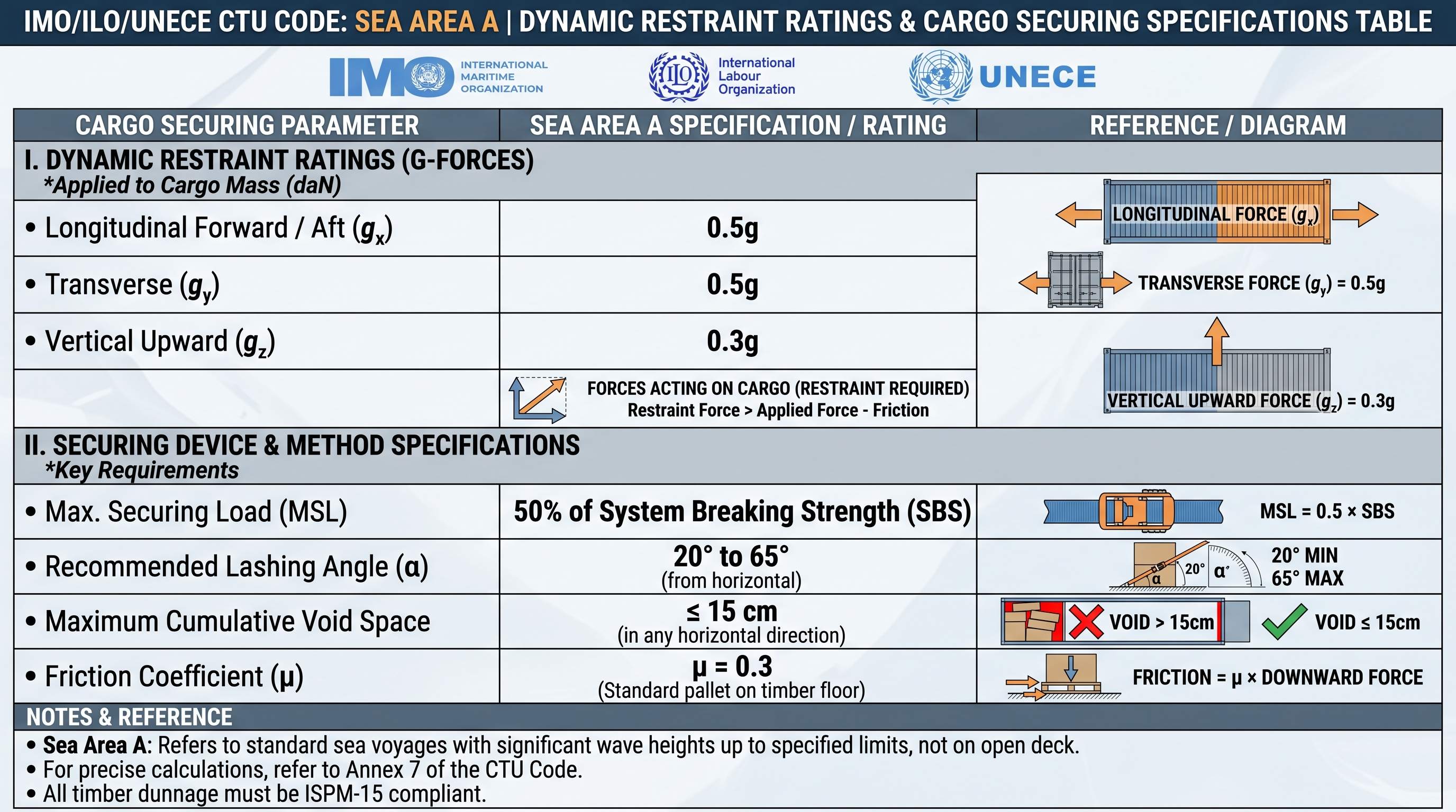
Sea Area A Dynamic Acceleration Envelope (Unrestricted Ocean Voyage)
| Motion Vector | Acceleration (c) | Dynamic Force (26t Payload) | Normal Force (cz = 0.5g) | Friction Force (μ = 0.3) | Net Unbalanced Force |
|---|---|---|---|---|---|
| Longitudinal Forward | 0.8g | 204.05 kN | 127.53 kN | 38.26 kN | 165.79 kN |
| Longitudinal Aft | 0.5g | 127.53 kN | 127.53 kN | 38.26 kN | 89.27 kN |
| Transverse Lateral | 0.8g | 204.05 kN | 127.53 kN | 38.26 kN | 165.79 kN |
| Transverse Tipping | 0.8g combined | Moment: Fy × hc | 0.5g × b/2 | Deficit creates roll moment | Lashing tension required |
5.1 Friction Interface Engineering and Rubber Mats
Unmodified contact interfaces between soft timber dunnage and untreated 28 mm container plywood exhibit static friction coefficients (μ) of only 0.30 to 0.40 under dry conditions, dropping to 0.20 when contaminated with oil or moisture. Relying on untreated timber to resist a 165.79 kN net sliding force overburdens internal container tie-down anchors.
Deploying certified 8 mm to 10 mm vulcanized granulated elastomeric friction pads (μ ≥ 0.60) beneath all longitudinal dunnage sleepers and column baseplates increases the base friction resistance under minimum vertical acceleration (cz = 0.5g) to:
This 100% increase in basal friction reduces tension demand on secondary lashing assemblies by 38.26 kN
5.2 Lashing Assemblies and Container Anchor Load Thresholds
Internal container anchor points have strict structural shear and tensile limits governed by ISO 1496-1:
- ▪ Internal floor anchor rings: 1,000 daN (10 kN) working load limit (rated breaking strength 2,000 daN), located along bottom side rails.
- ▪ Corner casting base eyes: 2,000 daN (20 kN) working load limit, located at internal corners.
- ▪ Upper side rail lashing points: 500 daN (5 kN) working load limit (designed solely for tarpaulins and light anti-chafing restraint).
| Securing Hardware | Size / Material | Lashing Capacity (LC) | Min. Break Strength | Paired Anchor Point | Permissible Working Angle |
|---|---|---|---|---|---|
| Transport Chain Assembly | 8 mm Grade 70 Alloy Steel | 4,000 daN | 8,000 daN | Corner Castings via Bridle | 30° to 60° direct tension |
| Heavy-Duty Webbing Strap | 50 mm PES Polyester | 2,500 daN | 5,000 daN | Bottom Side Rail Rings | 45° to 90° frictional tie-down |
| Ratchet Load Binder | 8 mm Drop-Forged Steel | 4,000 daN | 8,000 daN | Chain Assemblies | Inline direct pull |
| Friction Mats | 8 mm Vulcanized Granulate | μ ≥ 0.60 | 2.5 MPa compression | Floor / Dunnage Interface | Planar contact interface |
5.3 Longitudinal Positive-Form Timber Shoring and Void-Fill Bulkheads
CTU Code regulations prohibit transferring longitudinal dynamic crash-stop or pitch forces (up to 204 kN forward) directly onto container rear doors, which are certified to absorb only 0.4P (40% of total payload capacity uniformly distributed per ISO 1496-1). Concentrated structural steel tips will easily punch through corrugated steel door leaves.
Packaging layouts enforce positive-form timber shoring and void-fill bulkhead engineering. Void areas between bundle ends and corner posts are blocked with custom timber bulkheads constructed from European Spruce or Douglas Fir (minimum strength class C24 per EN 338). Shoring frameworks utilize 100 mm × 100 mm longitudinal stringers, 50 mm × 100 mm horizontal spreaders, and 100 mm × 100 mm diagonal knee braces. These transfer all forward inertia directly into bottom side rails, front corner posts, and corner casting sills. Intermediate transverse void spaces exceeding 150 mm between bundle stacks are secured with cross-laminated timber bracing or heavy-duty Level 4 dunnage air bags (bursting pressure ≥ 300 kPa).
6. Marine Micro-Climate Management: Container Rain Mitigation and VCI Preservation Protocols
Packing geometry and weight distribution represent only half the export logistics challenge. Ocean voyages subject dense structural steel shipments to severe internal atmospheric cycles. Without active micro-climate regulation, a structural steel payload leaving the fabrication yard in sound condition can arrive at an overseas project site compromised by underfilm corrosion and wet storage staining.
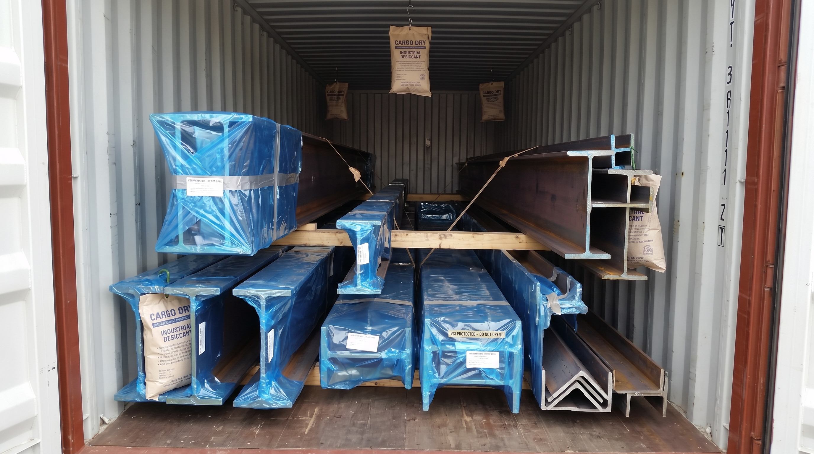
6.1 Thermodynamics of Ocean Transit and Intergranular Condensation
A standard 40HQ container functions as an uninsulated thermodynamic enclosure. Operating across trans-oceanic routes, ambient temperatures fluctuate drastically. During daylight in equatorial zones, direct solar radiation drives internal container temperatures upward to 65°C. Moisture trapped in ambient air, structural cavities, and organic timber vaporizes rapidly into the container envelope.
At night, ocean surface temperatures can drop to 12°C or lower. The thin corrugated corten steel container walls and roof cool far faster than the high-thermal-mass structural steel framing inside. When the temperature of the container roof drops below the internal dew point, moisture vapor condenses on the ceiling. Once surface tension is exceeded, this condensed liquid rains directly down onto the cargo beneath. This cycle repeats daily for 25 to 45 days, subjecting packaged steelwork to continuous wet-dry cycling in an oxygen-rich, high-salinity environment.
6.2 Coating Vulnerability and Vapor Corrosion Inhibitor (VCI) Deployment
While two-coat or three-coat marine epoxy-polyurethane systems (surface preparation to ISO 8501-1 Sa 2.5, nominal DFT 240 μm to 320 μm) provide long-term barrier protection, standing pools of acidic or high-chloride container rain induce osmotic blistering along flange edges. For hot-dip galvanized components (ASTM A123 / ISO 1461, 85 μm minimum local thickness), ponding condensation deprives the zinc coating of atmospheric carbon dioxide, forming hydrated zinc oxide and zinc hydroxide (white rust) and consuming the sacrificial zinc layer before installation.
To halt oxidation, structural components are sealed with advanced Vapor Corrosion Inhibitor (VCI) barriers:
- ▪ Co-extruded VCI film: Minimum 100 μm linear low-density polyethylene (LLDPE) film impregnated with amine carboxylate salts. Polar molecules vaporize continuously, electrostatically bonding to ferrous surfaces to form a monomolecular passivating shield.
- ▪ Bio-based VCI diffusers: Connection plates, high-strength bolts, and internal box-column cavities receive localized VCI foam emitters or breathable pouches to protect enclosed void spaces.
- ▪ Overlap seam sealing: Steel bundles are wrapped with a 150 mm overlap at all seams, sealed using heavy-duty VCI-compatible adhesive poly-tape to sustain chemical saturation.
| Transit Corridor / Severity | Primary Coating System | Target Dew Point Margin | Primary VCI Protocol | Desiccant Dosage |
|---|---|---|---|---|
| ISO 12944 C3: Temperate / Mild | Shop Primer + Epoxy (160 μm DFT) | ≥ 3°C above steel temp | 100 μm VCI film wrapping at bundle level | 1.5 kg CaCl2 / 10 m³ |
| ISO 12944 C4: Marine Moderate | Zinc-Rich + High-Build Epoxy (240 μm) | ≥ 5°C above steel temp | 120 μm VCI film + localized diffusers | 1.8 kg CaCl2 / 10 m³ |
| ISO 12944 C5-M: Direct Offshore | Zinc Silicate + Polyurethane (320 μm) | ≥ 8°C above steel temp | 150 μm reinforced VCI wrap + HSS emitters | 2.0 kg CaCl2 / 10 m³ |
| Galvanized: ASTM A123 / ISO 1461 | Hot-Dip Galvanizing (85–100 μm) | ≥ 5°C above steel temp | 100 μm neutral-pH non-acidic VCI wrap | 2.0 kg CaCl2 / 10 m³ |
6.3 Desiccant Sizing and Container Sealing Protocols
VCI films passivate surfaces, but bulk moisture extraction from the container air space is required to suppress gross dew point spikes. Desiccant selection prioritizes calcium chloride (CaCl2) over passive silica gel, which can desorb captured moisture back into the container atmosphere at temperatures exceeding 40°C.
Dosage requires 1.5 kg to 2.0 kg dry CaCl2 per 10 m³ container air envelope. In a standard 40HQ container (76.4 m³ gross volume), structural steel with dunnage occupies 30 m³ to 40 m³, leaving 36 m³ to 46 m³ of dynamic air. The standard dosage requires 8.0 kg to 10.0 kg of dry CaCl2 installed via hanging poles equipped with microporous Tyvek membranes, achieving a verified absorption capacity ≥ 200% by weight at 30°C and 90% RH. In addition, container labyrinth ventilation ports must be completely sealed with UV-stabilized butyl tape to prevent the desiccant from drawing external marine humidity during transit.
7. Logistics vs. Erection Sequencing: Reconciling Stowage Optimization with Site Erection (LIFO)
An operational divergence frequently occurs between freight logistics engineers and field erection superintendents. Logistics teams prioritize maximum volumetric stowage factor, pushing cubic capacity beyond 90% and payload weights toward the 26.5 metric ton line limit. Conversely, erection superintendents demand strict Last-In, First-Out (LIFO) accessibility matched to erection gridlines. Balancing cubic shipping efficiency with site assembly requirements is essential.
Direct-to-Erection vs. Intermediate Jobsite Laydown Workflow
- Crane Unloading: Riggers pick components directly from container threshold to foundation anchor bolts.
- Site Handling: Zero secondary handling cycles; requires zero intermediate laydown footprint.
- Constraint: Requires strict piece-mark sequence matching crane hook schedule.
- Yard Unloading: Telehandlers unstuff components into dedicated timber staging bays.
- Site Handling: 1 to 2 handling cycles; requires 1.5× to 2.5× building footprint area.
- Trade-Off: Maximum container cube density (88–94%) at the cost of double-handling.
| Evaluation Metric | Direct-to-Erection Strategy | Intermediate Laydown Staging |
|---|---|---|
| Container Stowage Efficiency | 72% to 82% cubic volume utilization | 88% to 94% cubic volume utilization |
| Secondary Handling Cycles | 0 cycles (direct pick to hook) | 1 to 2 complete handling cycles |
| Site Crane Standby Risk | High (requires exact arrival timing) | Low (yard acts as decoupling buffer) |
| Laydown Footprint Required | Negligible (chassis parking only) | 1.5× to 2.5× building footprint area |
| Coating Touch-Up Rate | 1% to 3% of surface area | 5% to 9% of surface area |
| Crane Demurrage Exposure | $250 to $450/hr on delays | $0 (unloaded by telehandler) |
| Net Handling Cost Delta | -$18 to -$32 per metric ton | Baseline field rigging cost |
7.1 Phased Erection Packaging Matrix
To balance container shipping efficiency with field assembly speed, structural steel shipments are segregated into phased component groupings:
| Erection Stage | Component Grouping | Target Erection Zone | Recommended Stowage Pattern | Target Utilization |
|---|---|---|---|---|
| Phase 1A | Anchor bolts, templates, base shims, baseplates | Foundation Grids A-1 to Z-9 | Container floor, wooden crates near door sill | 65% to 75% (Weight) |
| Phase 1B | Main building columns, portal bents, vertical bracing | Bay 1 to Bay 3 framing | Base-level dunnage tiers; web-to-web inverted | 80% to 85% (Mixed) |
| Phase 2A | Primary roof rafters, haunches, ridge monitors | Bay 1 to Bay 3 roof grid | Mid-level strapping with wall clearance | 82% to 88% (Volume) |
| Phase 2B | Crane runway beams, bracket assemblies, surge trusses | Runway Grids crane bays | Nested flatwise along floor center-of-gravity | 85% to 90% (Weight) |
| Phase 3A | Purlins, girts, eave struts, tie rods, fly braces | Envelope framing all bays | Bundled strapped packs in container upper quadrant | 90% to 95% (Cube max) |
| Phase 3B | Roof/wall cladding, insulation, flashings, fasteners | Exterior weather enclosure | Moisture-barrier protected ceiling stowage | 85% to 92% (Damage sens.) |
2-COL-04) matching 3D isometric vanning diagrams.
8. Pre-Vanning Quality Assurance Checklist, Axle Load Compliance, and Surveyor Sign-Off
Executing an engineered 40HQ container loading plan for prefab steel buildings requires strict pre-shipment quality gates before cargo enters the container. Structural checks begin with element readiness: fabricated Q355B and ASTM A992 built-up frames must have weld spatter dressed per AWS D1.1 and EN 1090-2 EXC2/EXC3 standards. Flush-ground web and flange splices prevent abrasive point-loading against adjacent members during transit. Coating systems (Sa 2.5 blast with 80 μm epoxy zinc-rich primer) must meet thickness tolerances measured per SSPC-PA 2, verified fully cured to avoid mechanical binding. Dunnage strapping mandates a calibrated tension meter verifying a minimum pre-tension of 500 daN across 50 mm strapping. Solid sawn timber used for chocking must carry legible ISPM-15 stamps and show wood moisture content strictly under 18%.
Weight distribution and axle loading demand systematic engineering control. Operations enforce dual-axle weighbridge protocols to achieve absolute SOLAS Chapter VI Verified Gross Mass (VGM) compliance. Axle load measurements confirm that the Longitudinal Center of Gravity (LCG) remains within 5% of the container geometric center (maximum permissible longitudinal offset of 299 mm from the mid-span of a 12.032 m internal floor length). Transverse Center of Gravity (TCG) offset is simultaneously restricted to under 3% of internal width (maximum 70 mm) to eliminate maritime rolling hazards and container chassis rollover risks during over-the-road transport.
| Inspection Parameter | Engineering Standard / Code | Yard Acceptance Criterion | Verification Tool / Protocol |
|---|---|---|---|
| Timber Moisture Content | ISPM-15 / CTU Code Annex 7 | < 18% moisture content | Digital pin-type resistance meter |
| Dunnage Strap Pre-Tension | EN 12195-2 / WSTDA-T-1 | ≥ 500 daN verified | Calibrated inline strap tension gauge |
| Total Container Mass (VGM) | SOLAS Chapter VI, Reg 2 | Verified Gross Mass within ±200 kg | Certified digital weighbridge (Method 1) |
| LCG Axle Load Eccentricity | CTU Code Section 8.2 | Within ±5% of geometric center | Dual-axle weighbridge balance test |
| Coating Barrier Thickness | SSPC-PA 2 / ISO 19840 | Sa 2.5 blast; 80 μm min DFT | Magnetic pull-off thickness gauge |
| Final Security Seal | ISO 17712:2013 Clause 5/6 | High-security bolt seal intact | Visual audit and pull-test verification |
Independent marine cargo surveyors supervise final container pack certification under the IMO/ILO/UNECE CTU Code. The surveyor executes a mandatory 4-stage photographic audit: Stage 1 documents the clean, empty container interior, structural crossmembers, and flooring condition; Stage 2 captures mid-tier framing, interleaving EPDM rubber friction mats, and intermediate bundling bands; Stage 3 records completed timber falsework, 100 mm × 100 mm end-wall chocking, and cross-braced diagonal lashings; Stage 4 logs shut container doors displaying identification numbers and the ISO 17712 High-Security Bolt Seal through the locking cam keeper.
9. Governing Structural Codes & Marine Logistics References
The design criteria, packaging calculations, and dynamic restraint metrics in this guide comply with the following international structural and maritime cargo codes:
Base Plate and Anchor Rod Design (Second Edition)
Fisher, J. M., & Kloiber, L. A. (American Institute of Steel Construction, 2006).
Building Code Requirements for Structural Concrete
Chapter 17: Anchoring to Concrete — American Concrete Institute (2019).
Standard Specification for Anchor Bolts
Steel, 36, 55, and 105-ksi Yield Strength — ASTM International (2020).
Code of Standard Practice for Steel Buildings and Bridges
Section 7.5: Anchor Rods and Foundation Bolting — AISC (2022).
Eurocode 3: Design of Steel Structures
Part 1-8: Design of joints — European Committee for Standardization (CEN, 2005).
Eurocode 2: Design of Concrete Structures
Part 4: Design of fastenings for use in concrete — CEN (2018).
Execution of Steel Structures & Aluminium
Technical requirements for steel structures (EXC2 & EXC3) — CEN (2018).
Mechanical Properties of Fasteners
Carbon steel & alloy steel bolts, screws and studs — ISO (2013).
Upstream Precision: How XinQiao Steel Eliminates Site Erection Headaches
The smoothest construction projects are those where the risk of field error is engineered out long before steel leaves the fabrication plant. When building in remote overseas destinations where specialized heavy equipment and certified rigging crews are expensive, prefabricated structural components must fit together seamlessly upon arrival.
Operating a 60,000 ㎡ heavy industrial steel manufacturing facility in Taian, China, XinQiao Steel (Shandong XinQiao Steel Structure Co., Ltd.) solves overseas assembly challenges at the fabrication source: