Prefabricated Multi-Storey Steel Schools & Hospitals: Seismic Safety and Rapid Turnkey Deployment
Forensic post-earthquake evaluations of the 2008 Wenchuan, 2011 Christchurch, and 2023 Kahramanmaraş seismic events documented clear structural vulnerability patterns across educational and medical buildings. Unreinforced masonry and non-ductile concrete shear walls exhibit catastrophic brittle shear failure under moderate-to-severe ground motions due to lack of flexural ductility and tensile rebar confinement. To protect life safety and preserve continuous emergency operations, modern engineering practice specifies prefabricated multi-storey steel framing, delivering up to a 45% reduction in seismic base shear and enabling rapid turnkey commissioning.

Specialist in industrial PEB detailing, AISC 360 connection design, and overseas turnkey project delivery at Shandong XinQiao Steel Structure Co., Ltd.
Table of Contents & Quick Navigation
1. Seismic Vulnerability in Critical Infrastructure: The Shift from Brittle Masonry to Ductile Steel
In unreinforced masonry (URM) and non-ductile cast-in-place reinforced concrete (RC) frames, high cyclic shear demands generate diagonal tension cracking across load-bearing piers and non-ductile beam-column joints. Once concrete spalling initiates and masonry mortar beds shear, degradation of lateral resistance accelerates rapidly, resulting in pancake collapse modes triggered by unmitigated P-Δ effects. To resolve these life-safety failures, modern engineering practice specifies prefabricated multi-storey steel framing, replacing low-ductility structural systems with factory-engineered steel frameworks.
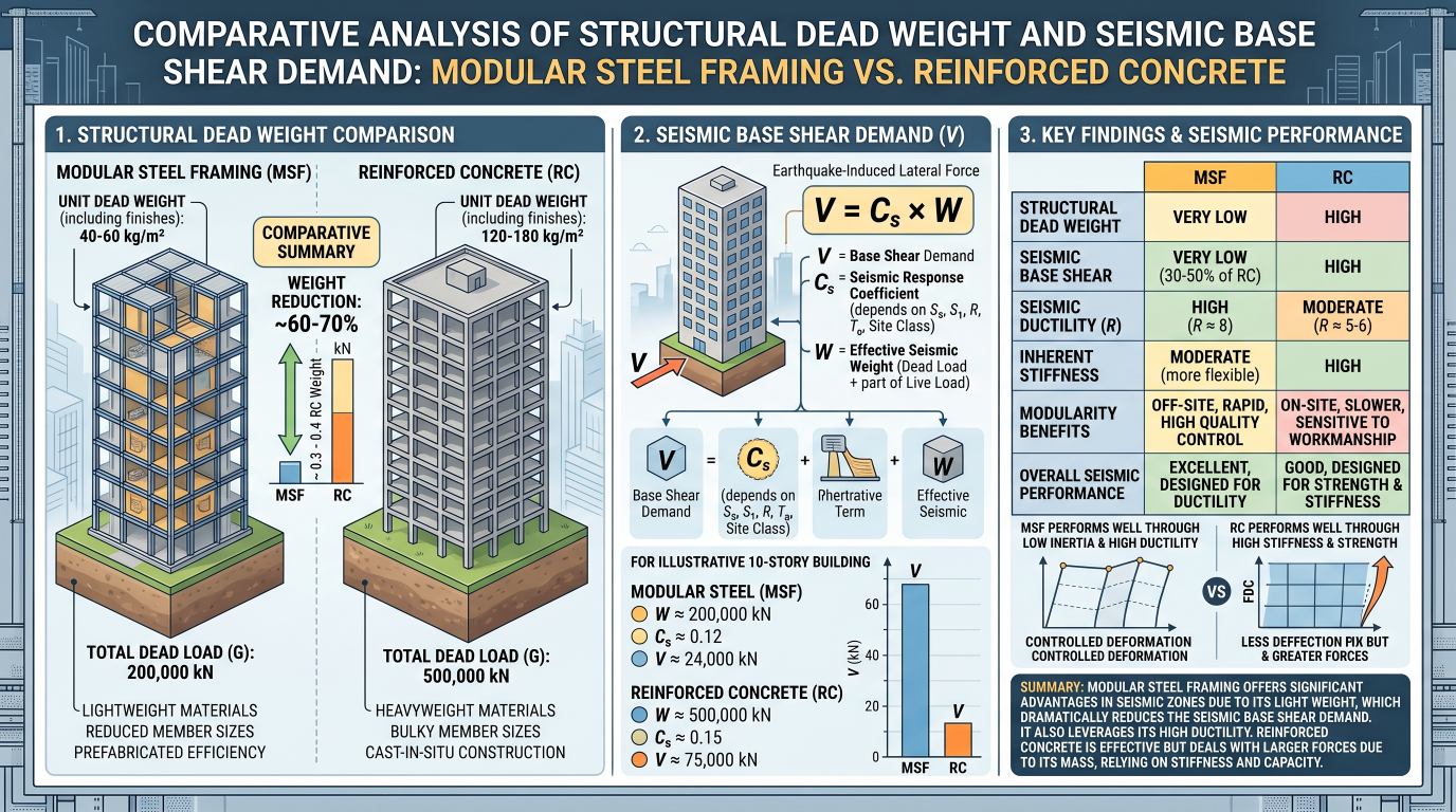
The dynamic physics of seismic response dictates that base shear demand (Vb) is governed directly by reactive building mass (W), represented through equivalent lateral force calculations (Vb = Cs · W). Lightweight steel structural systems reduce total building mass by 40% to 60% compared to monolithic concrete, directly cutting kinetic energy absorption demands during seismic excitation. Monolithic concrete structures dissipate dynamic energy via concrete cracking, rebar bond failure, and permanent pinching of hysteretic curves. In contrast, structural steel framing (fabricated using ASTM A992 or GB/T 1591 Q355B) delivers wide, stable hysteretic loops. Symmetrically placed energy-dissipating zones, such as Reduced Beam Sections (RBS per AISC 358-16) or eccentrically braced links (AISC 341-16), deform plastically without sacrificing gravity load capacity.
| Structural System Typology | Ductility Factor (R / q) | Dead Load (kg/m²) | Base Shear Demand (Vb / W) | Failure Mechanism Under Overload | Target Recovery Window |
|---|---|---|---|---|---|
| Unreinforced Masonry (URM) | 1.5 | 1,100 – 1,450 kg/m² | 0.28 – 0.35 | Brittle out-of-plane flexure & diagonal bed shear | Complete loss / Demolition |
| Non-Ductile Cast-in-Place RC | 2.5 – 3.0 | 800 – 1,150 kg/m² | 0.18 – 0.24 | Shear-compression failure, column hinge crushing | 6 to 18 months retrofitting |
| Prefabricated Steel SMF / BRBF | 8.0 | 320 – 480 kg/m² | 0.08 – 0.12 | Controlled flexural yielding of ductile beam links | Immediate occupancy to 72 hrs |
Under China GB 50011-2010 (2016 Edition), US IBC 2024 / ASCE 7-22, and Eurocode 8 (EN 1998-1), design goals for critical facilities have transitioned from basic collapse prevention to functional recovery. Functional recovery criteria require critical infrastructure (Risk Category III/IV) to remain structurally sound and re-occupiable within 72 hours post-MCE (Maximum Considered Earthquake). Achieving this performance level requires strict fabrication control: structural steel fabrications must comply with EN 1090-2 EXC3 and AWS D1.1 / AWS D1.8 seismic welding requirements, CNC plasma cutting tolerances within ±0.5 mm, anchor bolt layouts controlled to ±3 mm per AISC Design Guide 1 Section 2.3, and primary framing surface preparation blast-cleaned to ISO 8501-1 Sa 2.5 with an 80 μm DFT epoxy zinc-rich primer system to safeguard structural integrity across the building lifecycle.
2. Lateral Force-Resisting Systems (SFRS) and Seismic Base Shear Derivation in Multi-Storey Steel
Seismic force mitigation in multi-storey framing is governed directly by total building mass and the energy dissipation mechanics of the lateral force-resisting system (SFRS). Under ASCE 7-22 Section 12.8 and Eurocode 8 (EN 1998-1 Section 4.3.3.2), equivalent lateral force (ELF) procedures establish the seismic base shear (V) as a function of the seismic response coefficient (Cs) and the effective seismic weight (W):
Where SDS represents design spectral response acceleration in the short period range, R is the response modification coefficient, and Ie is the importance factor (assigned as 1.25 to 1.50 for critical educational and healthcare occupancies). A typical cast-in-place reinforced concrete floor plate imposes a structural dead load between 8.0 kN/m² and 12.0 kN/m² (averaging 10.5 kN/m²). Conversely, prefabricated modular steel framing configured with profiled steel composite decking and lightweight concrete topping imposes a self-weight of only 2.5 kN/m² to 3.5 kN/m² (averaging 3.2 kN/m²).
Ductility and Dissipation Mechanics Across Steel SFRS Typologies
Buckling-Restrained Braced Frames (BRBF)
BRBF systems achieve an AISC 341-22 response modification coefficient of R = 8, dissipating dynamic energy via stable yielding of a low-yield steel core under both tension and compression cycles. An unbonded mortar-filled steel casing prevents global flexural buckling.
Special Moment Frames (SMF)
SMF assemblies deliver architectural layout flexibility while providing high inelastic rotational capacity (θ ≥ 0.04 rad). AISC 358-22 prequalified connections (RBS and BSEEP) ensure plastic hinge relocation away from column faces.
Modular Space Frames with Infill Panels
Designed for accelerated erection schedules, modular cassettes incorporate perimeter cold-formed or hot-rolled steel shear panels acting as structural diaphragms (R = 6.5, Cd = 4.5), joined by ASTM A354 Grade BD high-tensile corner fittings.
| SFRS Typology | Governing Standard | Response Factor (R) | Overstrength (Ω0) | Deflection (Cd) | Design Drift Limit (Δa) | Steel Weight Range |
|---|---|---|---|---|---|---|
| Buckling-Restrained Braced Frame (BRBF) | AISC 341-22 / EN 1998-1 | 8.0 | 2.5 | 5.0 | 0.010 hsx (Risk IV) | 48 – 62 kg/m² |
| Special Moment Frame (SMF - RBS/BSEEP) | AISC 358-22 / AISC 341-22 | 8.0 | 3.0 | 5.5 | 0.010 hsx (Risk IV) | 58 – 75 kg/m² |
| Modular Space Frame with Infill Panels | AISC 341-22 / AISI S400 | 6.5 | 2.5 | 4.5 | 0.010 hsx (Risk IV) | 42 – 54 kg/m² |
| Monolithic RC Shear Wall (Baseline) | ACI 318-19 / ASCE 7-22 | 5.0 | 2.5 | 5.0 | 0.010 hsx (Risk IV) | Rebar: 85–110 kg/m³ |
3. Inter-Storey Drift Control and Regulatory Compliance for Risk Categories III and IV
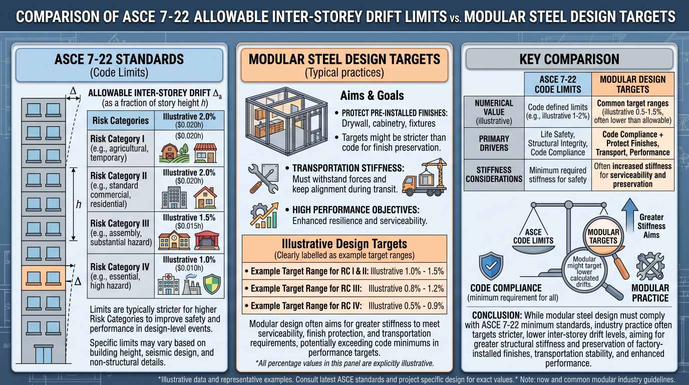
Designing structural steel framing for high-occupancy and critical-operations facilities requires strict adherence to lateral deformation limits under seismic loading. Under ASCE 7-22 Section 12.12.1 and IBC 2024 Table 1604.5, educational facilities sheltering large student bodies are classified as Risk Category III (Ie = 1.25), whereas acute healthcare facilities with 24/7 surgical suites and emergency rooms fall under Risk Category IV (Ie = 1.50). The importance factor Ie = 1.50 scales design seismic forces up by 50%, requiring structural steel systems to maintain elastic or near-elastic response during moderate ground shaking to ensure immediate occupancy.
| Performance Parameter | Risk Cat II (Commercial) | Risk Cat III (Schools) | Risk Cat IV (Hospitals) | Governing Code |
|---|---|---|---|---|
| Importance Factor (Ie) | 1.00 | 1.25 | 1.50 | ASCE 7-22 Tab. 1.5-2 |
| Allowable Elastic Drift (Δa) | 0.020 hsx | 0.015 hsx | 0.010 hsx | ASCE 7-22 Tab. 12.12-1 |
| Max Stability Coeff. (θmax) | ≤ 0.25 | ≤ 0.25 | ≤ 0.25 | ASCE 7-22 Sec. 12.8.7 |
| Non-Structural MEP Racking Limit | 0.020 hsx | 0.010 hsx | 0.005 hsx | NFPA 13 / NFPA 99 |
| Post-DBE Residual Drift Target | No prescriptive limit | < 0.75% | < 0.50% | FEMA P-58 |
| Base Frame Steel Tonnage Range | 42 – 55 kg/m² | 52 – 68 kg/m² | 72 – 95 kg/m² | Shop Fabrication Datum |
Second-order P-Δ effects must be verified under dynamic nonlinear displacement regimes per ASCE 7-22 Section 12.8.7. The stability coefficient, θ, is evaluated at each storey level:
Second-order P-Delta stability coefficients (θ) must remain strictly below θmax = 0.50 / (β · Cd) ≤ 0.25 to prevent progressive collapse in tall modular steel stacks.
Limiting residual drift to less than 0.5% after a Design Basis Earthquake (DBE) is necessary to ensure post-disaster operational continuity and prevent structural condemnations. Factory CNC drilling lines maintain bolt-hole positioning within ±0.5 mm across multi-tier connection plates, while anchor bolt alignments on foundation interfaces are held within ±2 mm tolerances. Using heavy ASTM A992 / Q355B structural columns joined by complete-joint-penetration (CJP) welds certified under AWS D1.1 ensures that modular column-to-column connections transfer lateral shears elastically, avoiding soft-storey mechanisms and preserving utility corridors during seismic events.
4. Structural Joint Detailing: Inter-Module Shear Keys, Vertical Tension Ties, and Diaphragm Transfer
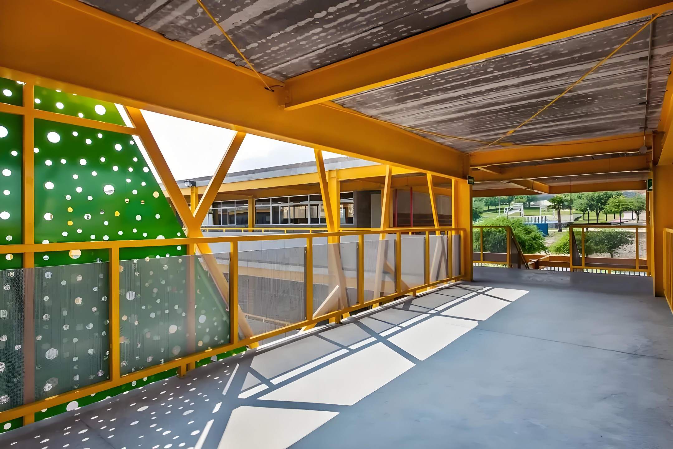
Volumetric modular steel construction requires direct load path continuity across segmented units to prevent localized stress concentrations and joint unseating. Horizontal floor cassettes must resist high lateral inertial loads without relying on the continuous cast-in-place concrete decks found in traditional framing. Modular floor cassettes function as composite diaphragms using cold-formed corrugated steel decking with engineered concrete topping (50 mm to 75 mm normal weight concrete over 0.9 mm to 1.2 mm profile steel deck) or heavy-duty rigid fiber-cement board subfloors fastened to perimeter rim beams. Lateral forces migrate from the diaphragm field into perimeter collector angles, through intermediate bolted splice plates, and directly into localized column nodes.
| Connection Component | Material Specification | Nominal Design Capacity | Structural Function | Shop / Erection Standard |
|---|---|---|---|---|
| Machined Shear Key | ASTM A572 Gr 50 / Q355B | 120 – 150 kN / node | In-plane diaphragm shear transfer | CNC ±0.5 mm, milled face |
| Slip-Critical Bolts | ASTM F3125 Gr A490 / Cl 10.9 | 185 kN slip res. / M24 | Collector force transfer across chords | AISC 360-16, Class B (μ ≥ 0.50) |
| Vertical Tension Tie | ASTM A193 Gr B7 / Cl 10.9 | 350 – 850 kN continuous | Multi-storey overturning & uplift | Hydraulic pre-tensioning |
| Cast Steel Corner Node | ASTM A216 Gr WCB / G20Mn5 | ≡ Column Capacity (Pn) | 3-axis structural node convergence | AWS D1.1 / Ultrasonic NDT |
| Slotted Bearing Shims | ASTM A36 / Grade 250 | 250 MPa bearing resistance | Vertical height leveling adjustment | AISC 360 Sec. J3 Table J3.3 |
To maintain rigid structural load continuity while accommodating ±2 mm erection tolerances, primary volumetric frameworks utilize automated robotic welding cells to maintain strict geometric tolerances: overall module length and width within ±1.5 mm, squareness across diagonals within 2.0 mm, and column verticality within 1:1000. In accordance with AISC 360-16 Chapter J and Section J3.3, oversized or short-slotted holes are fitted with 8 mm thick ASTM F436 hardened steel plate washers. Finger shims machined from structural grade steel permit precise leveling of stacked corner castings, preventing uneven bearing across vertical column faces and ensuring full structural contact area prior to post-tensioning.
5. Clinical and Educational Building Physics: Dynamic Vibration Dampening and MEP Isolation
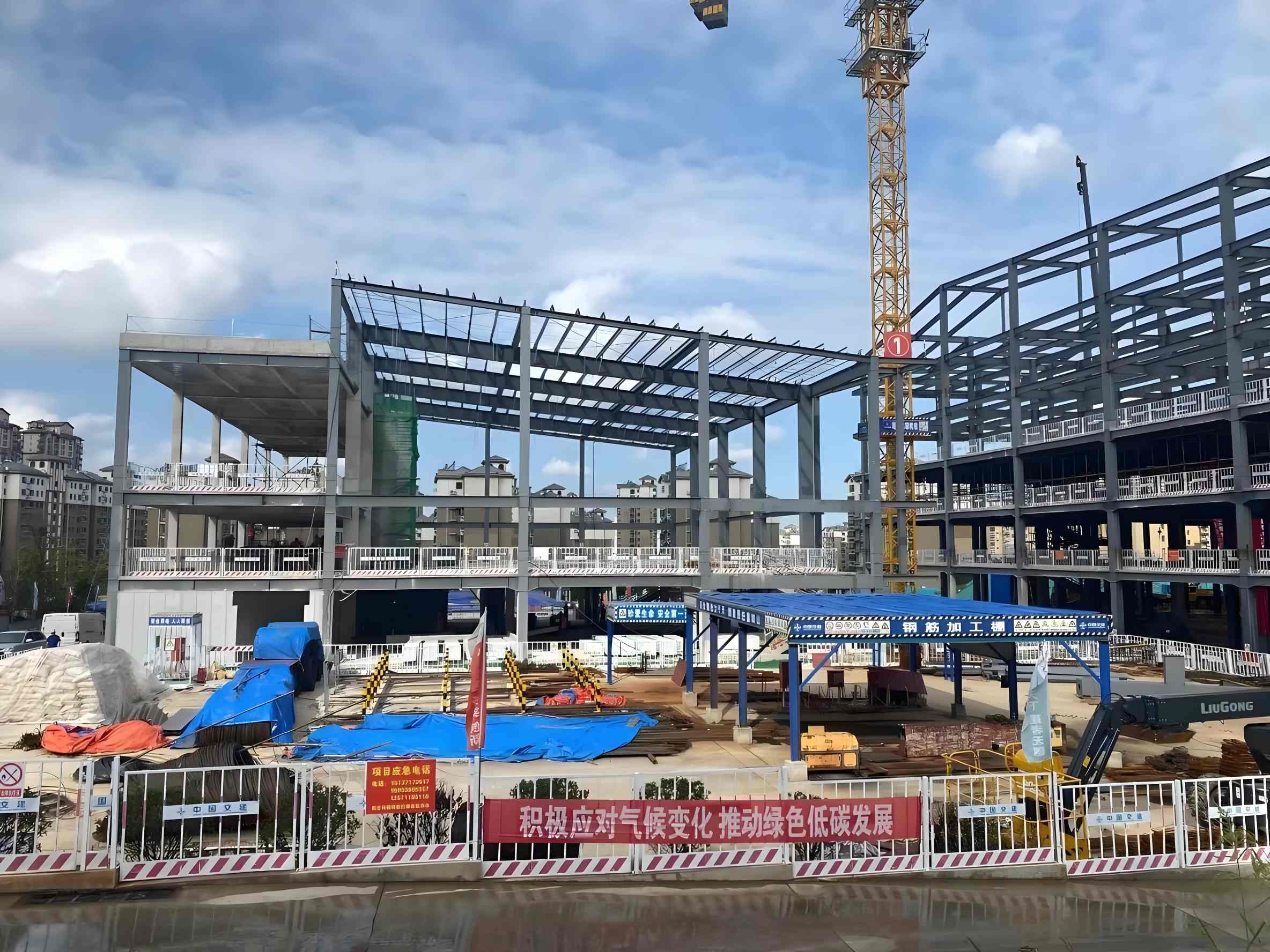
Engineering structural framing for institutional healthcare and academic infrastructure requires balancing dynamic stiffness against rapid assembly. In modular hospital and school designs, floor system performance cannot be treated as a basic static deflection problem (L/360 or L/480). Footfall-induced resonance and mechanical vibration transmission directly jeopardize delicate surgical procedures, diagnostic imaging clarity, and learning comprehension.
Dynamic Floor Tuning and AISC Design Guide 11 Compliance
Human walking pacing frequencies typically range between 1.5 Hz and 2.5 Hz, with higher harmonics generating significant kinetic energy up to 8.0 Hz. Floor natural frequencies must be engineered above 8.0 Hz to avoid resonant excitation induced by footfall harmonics in primary hospital corridors and school hallways. To safeguard sensitive clinical equipment, AISC Design Guide 11 specifies velocity limits of 100 μm/s (4,000 μ-in/s) for general surgical suites and 50 μm/s for micro-surgery, necessitating dynamic mass-tuning of modular steel floor cassettes.
| Module Spatial Function | Governing Standard | Natural Freq. (fn) | Peak Velocity (vmax) | Acoustic Partition | Primary Damping Mechanism |
|---|---|---|---|---|---|
| General Operating Rooms | AISC DG 11 / ISO 10121 | ≥ 8.5 Hz | 100 μm/s (4,000 μ-in/s) | STC 50 | 120 mm concrete slab + viscoelastic base |
| Micro-Surgery & Eye Theaters | AISC DG 11 / ASHRAE V-C | ≥ 10.0 Hz | 50 μm/s (2,000 μ-in/s) | STC 52 | Neoprene pads + mass-tuned stringers |
| Imaging Suites (MRI / CT) | OEM Spec / AISC DG 11 | ≥ 9.0 Hz | 25 – 50 μm/s | STC 55 | High-stiffness composite framing + inertia pad |
| Primary School Classrooms | ANSI/ASA S12.60 / IBC | ≥ 6.5 Hz | 400 μm/s (16,000 μ-in/s) | STC ≥ 50 | Double-stud cavity + dense mineral wool |
| Lecture Theaters & Auditory Pods | ANSI/ASA S12.60 | ≥ 7.0 Hz | 200 μm/s (8,000 μ-in/s) | STC 55 | Resilient drywall channel clips + tuned slab |
Factory-certified medical gas piping installed in modular chassis incorporates flexible stainless steel braided seismic loop joints capable of absorbing differential inter-module drift up to ±50 mm without pressure loss per NFPA 99. In educational modules, ANSI/ASA S12.60 acoustic performance (STC ≥ 50 to 55) is achieved using two independent cold-formed steel stud rows (0.9 mm thickness, 90 mm depth) separated by a 25 mm acoustic air break and filled with 70 kg/m³ high-density basalt mineral wool, completely eliminating flanking noise transmission between adjacent classrooms.
6. DfMA Manufacturing Protocols, Shop Tolerances, and Intumescent Fire Protection
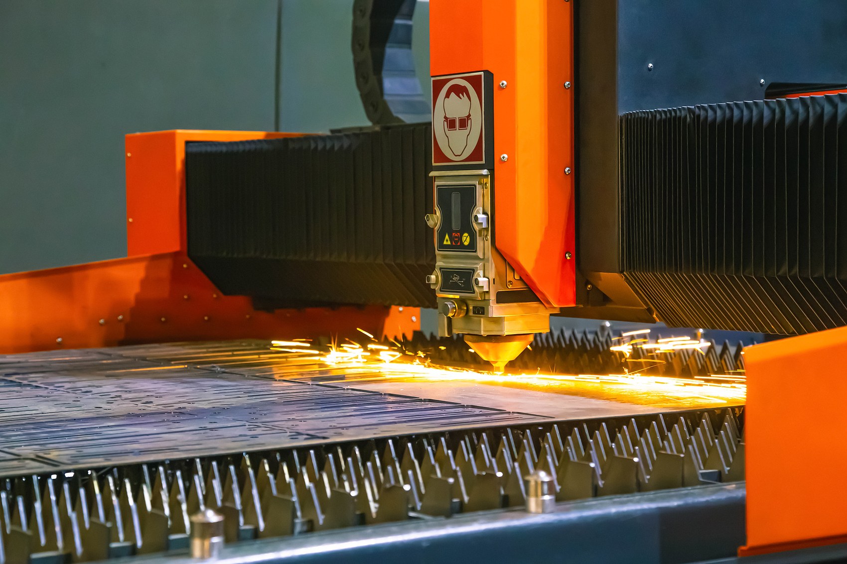
Industrialized Design for Manufacture and Assembly (DfMA) shifts critical structural operations from uncontrolled jobsite environments into precision shop floors. Automated CNC heavy-gantry laser and high-definition plasma cutting systems achieve edge cut tolerances within ±0.5 mm, maintaining root face and bevel angle precision (±1.0 degree) for pre-qualified Complete Joint Penetration (CJP) weld preparations.
| Quality Metric / Parameter | DfMA Controlled Shop Execution | Conventional Field Erection | Governing Standard |
|---|---|---|---|
| CNC Plate Cutting & Milling | ±0.5 mm | ±2.0 mm to ±3.0 mm | ISO 9013 Class 2 / EN 1090-2 |
| Volumetric Module Orthogonality | ±1.5 mm per 12 m span | ±6.0 mm per 12 m span | AISC COSP / EN 1090-2 |
| Bolt Hole Pitch Tolerance | ±0.4 mm center-to-center | ±1.5 mm center-to-center | AISC 360-16 Tab. J3.3 |
| Surface Cleanliness Profile | Sa 2.5 to Sa 3.0 (50–75 μm) | St 2 to Sa 2.0 (inconsistent) | ISO 8501-1 / SSPC-SP 10 |
| CJP Weld Volumetric Examination | 100% PAUT / TOFD inline gate | 10% to 25% random sampling | AWS D1.8 / EN 1090-2 EXC3 |
| Intumescent Fireproofing DFT | ±5% calibrated target profile | -15% to +35% uneven passes | SSPC-PA 2 / EN ISO 2808 |
For institutional facilities in active seismic zones, 100% non-destructive ultrasonic testing is performed on all complete-joint-penetration (CJP) moment frame welds using Phased Array Ultrasonic Testing (PAUT) and Time-of-Flight Diffraction (TOFD). Following automated shot blasting to ISO 8501-1 Sa 2.5, structural members receive a two-pack zinc-rich epoxy primer (60 to 80 μm DFT) followed by shop-applied thin-film intumescent fireproofing calibrated to section factors. These shop-applied intumescent systems achieve UL 263 2-hour and 3-hour fire-resistance ratings with zero cracking under transport vibrations up to 1.5g.
7. Turnkey Site Erection Sequencing, Crane Logistics, and Parallel Foundation Scheduling
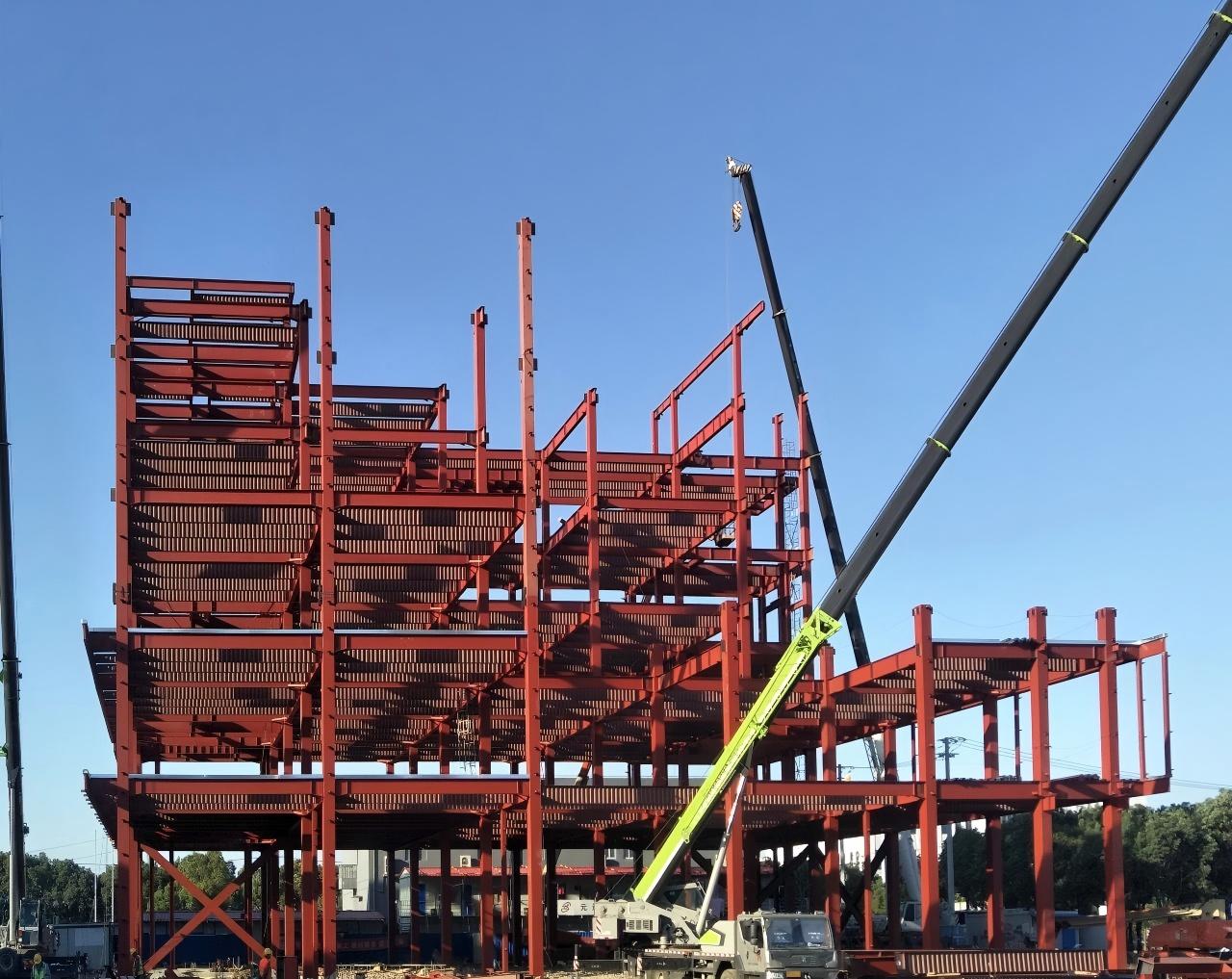
Traditional construction sequences subgrade civil engineering, superstructure frame erection, building envelope closure, and internal MEP fit-out in series. Volumetric steel delivery decouples site preparation from vertical assembly, running the primary work streams concurrently. Parallel on-site civil works and off-site modular chassis manufacturing compress the overall hospital construction timeline from 24–36 months down to 12–16 weeks.
Step 1: Substructure Laser Verification and Shimming
Anchor bolt placement tolerances are governed by 3D laser scanning to maintain base plate alignment within ±1.0 mm prior to module landing. High-early-strength non-shrink cementitious grout beds conforming to ASTM C1107 are cast to exact finished floor datum levels.
Step 2: Controlled Descent and Module Positioning
The crawler crane hoists the unit directly from the transport trailer using custom multi-point spreader beams with hydraulic leveling pins. Riggers guide the chassis onto tapered CNC-machined locating pins welded to lower module corner blocks.
Step 3: Column Splicing and High-Strength Bolting
Inter-module structural junctions are joined using ASTM F3125 Grade A490 structural bolts tightened with calibrated electric shear wrenches to certified pretension per RCSC specifications. Vertical high-strength tie rods (ASTM A354 Grade BD) are post-tensioned through internal column voids.
Step 4: Marriage Wall Interface and Utility Interconnection
Module perimeters are sealed using fire-rated elastomeric intumescent gasketing and factory-installed EPDM compression seals. Vertical MEP utility risers feature quick-connect seismic-rated mechanical couplings, reducing field hookup labor by over 75%.
| Parameter / Milestone | Conventional In-Situ RC | Turnkey Volumetric Steel | Standard / Verification |
|---|---|---|---|
| Project Duration (200-Bed Facility) | 24 to 36 Months | 12 to 16 Weeks | ISO 21500 / Critical Path |
| Foundation & Structure Timeline | Sequential (Linear path) | Parallel (Concurrent civils & shop) | ACI 318 / AISC 360-16 |
| Anchor Bolt Placement Tolerance | ±3.0 mm to ±6.0 mm | ±1.0 mm (3D Laser Scan) | AISC 303-16 Sec. 7.5 |
| Erection Assembly Velocity | 2 to 4 Structural Bays / Day | 8 to 12 Finished Pods / Day | OSHA 1926 Subpart R |
| Hook Time per Unit / Pick | 45 to 60 Minutes (Unfitted) | 15 to 20 Minutes (Fully fitted) | Rigging Engineering Standard |
| Site Labor Density | 250 to 400 Workers Daily | 35 to 55 Workers Daily | Contractor Field Logs |
8. Techno-Economic Feasibility, Lifecycle Resilience, and Capital Asset Value
Procurement evaluations for institutional infrastructure frequently fall into the trap of comparing initial structural material bills of quantities while ignoring total cost of ownership (TCO) and capital capitalization velocity. Cast-in-place concrete structures impose extended site casting schedules, heavy subsoil loading, and unpredictable labor productivity variances. In contrast, shop-fabricated structural steel framing alters the financial return model by compressing project schedules by 40% to 60%. Early facility commissioning generates 12 to 18 months of acute healthcare operating revenue, amortizing upfront prefabrication costs within the first two quarters of clinical occupancy.
Substructure engineering yields immediate capex relief. Superstructure dead loads for multi-storey steel framing configured with composite decks (ASTM A992 / Q355B wide-flange beams with profiled metal decking) average 3.8 kPa to 4.5 kPa, compared to 8.5 kPa to 11.0 kPa for equivalent reinforced concrete shear wall designs. Consequently, foundational concrete and piling volumes are reduced by 30% to 45% due to the 50% dead load reduction of structural steel framing.
| Techno-Economic Metric | Traditional Cast-in-Place RC | Prefabricated Steel with BRBF | Financial / Operational Impact |
|---|---|---|---|
| Superstructure Dead Load | 8.5 to 11.0 kPa | 3.8 to 4.5 kPa | 50% dead load reduction |
| Foundation and Piling Volume | 100% baseline | 55% to 70% of baseline | 30% to 45% substructure capex savings |
| Erection Duration (15,000 m²) | 18 to 24 months | 7 to 9 months | 11 to 15 months accelerated revenue |
| On-Site Rework Contingency | 8.0% to 12.0% of capex | < 1.5% of capex | Net 6.5% to 10.5% project capex saved |
| Post-MCE Restoration | Demolition or 6–12 mo retrofit | 2 to 3 weeks fuse replacement | 80% lower post-disaster downtime |
| Property Insurance PML Estimate | 22% to 35% replacement value | 8% to 14% replacement value | 15% to 25% recurring premium reduction |
9. Governing Structural Codes & Design References
The seismic detailing criteria, tolerance thresholds, and dynamic structural calculations in this engineering manual comply strictly with the following international building standards:
Base Plate and Anchor Rod Design (Second Edition)
Fisher, J. M., & Kloiber, L. A. (American Institute of Steel Construction, 2006).
Building Code Requirements for Structural Concrete
Chapter 17: Anchoring to Concrete — American Concrete Institute (2019).
Standard Specification for Anchor Bolts
Steel, 36, 55, and 105-ksi Yield Strength — ASTM International (2020).
Code of Standard Practice for Steel Buildings and Bridges
Section 7.5: Anchor Rods and Foundation Bolting — AISC (2022).
Eurocode 3: Design of Steel Structures
Part 1-8: Design of joints — European Committee for Standardization (CEN, 2005).
Eurocode 2: Design of Concrete Structures
Part 4: Design of fastenings for use in concrete — CEN (2018).
Execution of Steel Structures & Aluminium
Technical requirements for steel structures (EXC2 & EXC3) — CEN (2018).
Mechanical Properties of Fasteners
Carbon steel & alloy steel bolts, screws and studs — ISO (2013).
Upstream Precision: How XinQiao Steel Eliminates Site Erection Headaches
The smoothest construction projects are those where the risk of field error is engineered out long before steel leaves the fabrication plant. When building in remote overseas destinations where specialized heavy equipment and certified rigging crews are expensive, prefabricated structural components must fit together seamlessly upon arrival.
Operating a 60,000 ㎡ heavy industrial steel manufacturing facility in Taian, China, XinQiao Steel (Shandong XinQiao Steel Structure Co., Ltd.) solves overseas assembly challenges at the fabrication source: