Multi-Span PEB Logistics Steel Warehouse Cost Saving: Column Grid & Structural ROI Analysis
Cut warehouse structural steel weight by 25%–42% and total turnkey CAPEX by 20%–35%. An engineering breakdown of how multi-span Pre-Engineered Building (PEB) frames exploit quadratic span mechanics, eliminate deep moment-resisting foundations, synchronize with NFPA 13 racking flue spaces, and optimize container shipping payloads.

Specialist in industrial PEB detailing, AISC 360 connection design, and overseas turnkey project delivery at Jinan XinQiao Steel Structure Co., Ltd.
Table of Contents & Quick Navigation
CAPEX Reality Check: The Financial and Structural Tipping Point of Multi-Span PEB
Logistics developers, third-party logistics (3PL) directors, and EPC cost estimators frequently fall into an expensive over-specification trap: demanding completely unobstructed clear-span floor plates under the assumption that any interior column compromises material handling. While a 30-meter clear-span portal frame is structurally practical, bending moments scale quadratically with span (M = wL2 / 8). As rafter spans extend further, rafter web depths, flange thicknesses, and lateral torsional buckling restraints escalate rapidly. The economic tipping point occurs at building widths between 45m and 60m, beyond which clear-span weight scales exponentially.
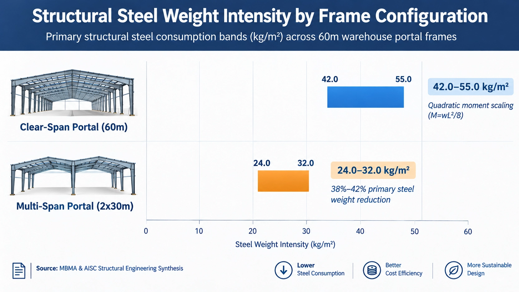
At widths exceeding 48 meters, forcing a clear span requires built-up rafter depths often exceeding 1,500 mm at the haunch. This drives up building ridge heights and conditioned HVAC volumes. By introducing one to three intermediate columns to create a multi-span rigid frame, engineers reset the effective span length L. Primary steel consumption drops from 42.0–55.0 kg/m² in clear-span to 24.0–32.0 kg/m² in multi-span configurations. Total turnkey CAPEX decreases by 20%–35% across structural steel and substructure scopes.
Structural and Commercial Comparison: Clear-Span vs. Multi-Span Logistics Facilities
The following baseline metrics reflect audited fabrication and site data based on ASTM A572 Grade 50 (or GB/T 1591 Q355B) structural steel, fabricated under EN 1090-2 EXC2 and AWS D1.1 execution standards:
| Parameter / Framing Scheme | 60m Clear-Span Portal Frame | 60m Multi-Span (2×30m Modules) | 72m Multi-Span (3×24m Modules) |
|---|---|---|---|
| Primary Frame Steel Intensity | 46.5 – 54.0 kg/m² | 27.5 – 33.0 kg/m² | 23.5 – 28.0 kg/m² |
| Haunch Rafter Web Depth | 1,450 – 1,700 mm | 750 – 900 mm | 600 – 750 mm |
| Column Base Fixity & Foundation Load | High moment base; large overturning | Pinned/semi-rigid base; low moment | Pinned base; minimal moment |
| Civil Footing Concrete Volume | 1.8 – 2.4 m³ per perimeter base | 0.9 – 1.2 m³ per perimeter base | 0.7 – 0.9 m³ per perimeter base |
| Fabrication CNC Plasma Cutting | Web cutting waste exceeds 8.5% | Web cutting waste under 3.5% | Web cutting waste under 2.5% |
| Turnkey Structural Superstructure CAPEX | $82 – $105 / m² | $58 – $71 / m² | $49 – $62 / m² |
The cost penalty of clear spans extends beneath the finished slab. Clear-span rafters produce massive horizontal thrusts and base bending moments under governing load combinations (AISC 360-16 and ASCE 7-16 wind uplift/drift criteria). Designing foundations to resist these overturning moments per ACI 318-19 and AISC Design Guide 1 Section 2.3 demands large reinforced concrete spread footings with deep rock anchors or driven piles. In contrast, multi-span frames use pinned interior column bases that transmit almost pure axial loads. Baseplate anchor bolt layouts maintain standard workshop tolerances (±3 mm), reducing footing excavation volumes and concrete usage by up to 45%.
Modern automated distribution centers do not require open, column-free spaces across a 60-meter envelope. By setting interior column grids to match warehouse pallet racking configurations (such as 12m to 18m bay pitches aligning directly within back-to-back rack flues), interior columns sit completely outside operational paths. Very Narrow Aisle (VNA) trucks, autonomous mobile robots (AMRs), and reach trucks navigate aisles without interference, while the developer avoids paying for thousands of tons of redundant structural steel. Primary frames receive automated Sa 2.5 centrifugal shot blasting and an 80 μm dry film thickness (DFT) epoxy zinc-rich primer directly in the fabrication line, yielding high structural efficiency and rapid field erection.
Moment Mechanics & Structural Efficiency: Exploiting the Quadratic Span Law
Structural steel mass in logistics facilities is directly controlled by beam flexure. The fundamental design equation for transverse bending under uniform distributed gravity loading (w) reveals that maximum internal bending moment scales quadratically with clear-span distance:
When specifying wide industrial footprints, structural engineers must choose between clear-span portal frames and continuous multi-span frames supported by interior columns. Bending moments scale quadratically (M = wL2/8); halving span length reduces primary moment demand by up to 50%–60%. This mechanical principle represents the foundational driver behind Multi-Span PEB Logistics Warehouse Cost Saving strategies, transforming heavy, flexure-governed frames into lightweight, stiffness-optimized continuous structural systems.
Single Clear-Span (48m)
Moment Demand: HighDeep parabolic positive bending envelope across full 48m width; governed by severe haunch flexure (1,840 kNm) and mid-span deflection.
Multi-Span Continuous (2 × 24m)
Moment: 50%–60% LowerContinuity over the interior column splits the effective span in half, dropping peak design moment to 790 kNm and converting center post loads into pure axial thrust (Pu).
In a single clear-span portal frame of 48 meters, rafter design is dictated by peak flexural moments at the knee haunch and excessive mid-span deflection limits (L/180 to L/240). Splitting that frame into two 24-meter sub-spans using an interior column completely restructures the internal moment diagram. Instead of a single, deep parabolic positive moment envelope spanning the entire width, continuity shifts load path demands into moderate negative support moments directly over the center column.
Because balanced gravity loads generate opposing rotations across the center support, interior columns carry axial compression loads with minimal bending, resulting in high structural efficiency. Per AISC 360-16 Chapter E, these interior columns can be sized as slender, lightweight hollow structural sections (HSS) or compact rolled wide-flange shapes designed almost purely for axial thrust (Pu) under AISC 360-16 Equation E3-1, completely eliminating massive flexural cross-sections.
This redistribution yields immediate structural down-gauging across all main frame components:
Rafter web depths shrink from 1200mm–1600mm down to 600mm–850mm, reclaiming 45% of rafter depth. This profile contraction reduces raw plate cutting width, lowers building envelope volume, and frees up vertical logistics clearance below the haunch line.
Flange thicknesses decrease from 12mm–16mm plate profiles down to 6mm–8mm high-tensile steel (345 MPa / Grade 50). Thinner flanges avoid expensive multi-pass full-penetration groove welds, allowing single-pass automated submerged arc welding (SAW) per AWS D1.1 at the factory.
Shallower rafters dramatically reduce compression flange unbraced length (Lb) requirements per AISC 360-16 Chapter F, reducing the total count of intermediate purlin fly-braces and lateral stiffeners.
| Metric / Parameter | 1 × 48m Clear-Span Frame | 2 × 24m Multi-Span Frame | 3 × 16m Multi-Span Frame |
|---|---|---|---|
| Peak Design Moment (Mu) | 1,840 kNm | 790 kNm | 420 kNm |
| Rafter Haunch Depth | 1,450 mm | 750 mm | 520 mm |
| Rafter Flange Plate | 16 mm × 300 mm | 8 mm × 200 mm | 6 mm × 180 mm |
| Interior Column Size | N/A (None) | HSS 250×250×6.0 | HSS 200×200×5.0 |
| Frame Steel Weight | 48.5 kg/m² | 26.8 kg/m² | 21.4 kg/m² |
| Factory Welding Volume | 100% (Baseline heavy fillets) | 48% (Automated single-pass) | 38% (High-speed single-pass) |
| Foundation Moment Anchor Load | Extreme (Large uplift piles) | Low (Pinned base dominates) | Minimal (Standard isolated pad) |
At our Jinan XinQiao fabrication facility, standardizing on multi-span configurations optimizes plate processing. Web plates are cut using precision multi-torch CNC plasma cutting systems operating within ±0.5 mm tolerances. The reduced web depths fit efficiently within standard 2-meter mother plate widths with minimal nesting scrap. Components pass through automatic shot blasting to Sa 2.5 cleanliness before receiving an 80 μm dry film thickness (DFT) epoxy zinc-rich primer coat. At the job site, foundation anchor bolts placed within ±3 mm tolerance easily receive the pinned base plates of axially loaded center posts, streamlining erection without the heavy cranes required to swing 1600 mm deep clear-span rafters into place.
Itemized BOQ Cost Breakdown: Clear-Span (60m) vs. Multi-Span (2×30m) Benchmark
Evaluating the structural balance of a 20,000 m² distribution facility (60m total building width × 333.33m length, with a 9.5m clear height and 9.0m longitudinal bay spacing) demonstrates that the Multi-Span PEB Logistics Warehouse Cost Saving is not an abstract concept. It is a direct mechanical outcome of moment distribution. When a design transitions from an unobstructed 60m clear-span portal frame to a 2×30m multi-span configuration incorporating a single central column line, the governing bending moments drop exponentially.
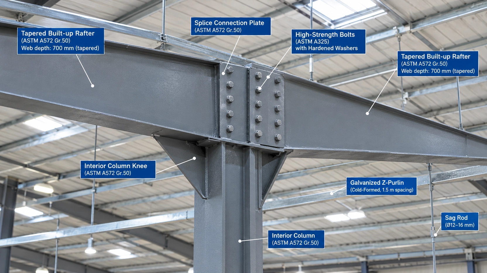
Under governing load combinations per AISC 360-16 and ASCE 7-16, the maximum gravity moment in a clear-span portal rafter scales with the square of the span (M ∝ wL2). Spanning 60m unsupported forces the engineer to specify primary built-up rafters with haunch depths reaching 1,500mm to 1,800mm, flange plates up to 28mm thick, and column bases designed for extreme overturning moments. Splitting that width into a 2×30m multi-span cuts the rafter design span in half. This reduces rafter depths to 700mm to 900mm and flange thicknesses to 12mm to 16mm using ASTM A572 Grade 50 (equivalent to GB/T 1591 Q355B) plate.
Deploying a 2×30m multi-span configuration on a 20,000 m² warehouse eliminates ~340 metric tons of primary structural steel. On average, primary steel weight drops from 42.5 kg/m² (850 metric tons total) in the clear-span layout to 25.5 kg/m² (510 metric tons total) in the 2×30m geometry. Raw material savings total $400,000 to $650,000 USD based on average fabricated steel spot rates, which range between $1,200 and $1,900 per metric ton delivered to port, depending on global hot-rolled coil indexes and processing surcharges.
The civil and structural foundations reflect an equally sharp delta. Clear-span portal frames transfer high base shears and flexural moments (Mx) directly to the perimeter pedestals. Resisting these forces under ACI 318-19 requires massive spread footings (typically 4.2m × 4.2m × 1.1m) or heavy bored piles paired with extensive tie beams to counteract soil bearing overstress and frame spread. The 2×30m multi-span configuration resolves gravity roof loads through interior pinned-base pipe or box columns (ASTM A500 Grade C), which carry axial compression with negligible moment transfer. As a result, perimeter footings decrease in volume by roughly 50%, generating $150,000 to $250,000 in foundation concrete and rebar savings across the 38 foundation grid lines.
Ocean shipping and field erection compound these economies. Deep 60m clear-span rafters require longitudinal segmentation into three or four pieces per half-span to fit inside standard 40ft High Cube containers. This introduces excessive bolted field splices with ASTM A325 or A490 tension bolts. The shallower 30m rafters nest tightly into container profiles, eliminating container cubing losses and cutting ocean freight volume by roughly 22%. On site, erectors avoid heavy tandem lifts with 70-ton mobile cranes and temporary shoring towers. Standard 25-ton cranes erect the 2×30m frames in single, balanced picks, reducing crane rental periods by 20 working days.
Primary steel and foundation concrete reductions generate substantial savings. Combined with lower freight costs and fewer crane hours, the turnkey square-meter cost drops from $140–$185/m² to $105–$135/m².
The itemized Bill of Quantities (BOQ) comparison below outlines the exact quantitative shift for this 20,000 m² logistics benchmark.
| Cost Component / BOQ Item | Clear-Span Base Case (1×60m) | Multi-Span Optimized (2×30m) | Variance (Cost & Material Delta) | Technical Standard / Fabrication Spec |
|---|---|---|---|---|
| Primary Structural Steel Frame | 850 t (42.5 kg/m²) at $1,450/t = $1,232,500 | 510 t (25.5 kg/m²) at $1,450/t = $739,500 | -$493,000 (-340 t / -40.0%) | ASTM A572 Gr 50 / Q355B; AWS D1.1 SAW; CNC cut ±0.5mm |
| Secondary Framing (Purlins & Girts) | 160 t (8.0 kg/m²) at $1,250/t = $200,000 | 145 t (7.25 kg/m²) at $1,250/t = $181,250 | -$18,750 (-15 t / -9.4%) | ASTM A653 SS Gr 50, Z275 galvanizing, continuous overlap |
| Substructure Concrete & Reinforcement | 1,850 m³ concrete + 195 t rebar = $485,000 | 1,020 m³ concrete + 105 t rebar = $268,000 | -$217,000 (-44.7% civil cost) | ACI 318-19; fc=30 MPa; ASTM A615 Gr 60; Anchor ±3mm |
| Surface Preparation & Shop Coating | 32,500 m² surface at $9.50/m² = $308,750 | 21,800 m² surface at $9.50/m² = $207,100 | -$101,650 (-32.9% paint area) | ISO 8501-1 Sa 2.5 shot blast; 80μm DFT epoxy zinc primer |
| Ocean Freight Logistics (40ft HC) | 78 containers at $3,600/box = $280,800 | 54 containers at $3,600/box = $194,400 | -$86,400 (-24 containers) | Breakbulk / 40HC container packing; tare limit optimization |
| Site Erection & Crane Rental | Dual 50t cranes (45 days) = $245,000 | Single 25t crane (28 days) = $125,000 | -$120,000 (-49.0% equipment) | AISC Code of Standard Practice (COSP); OSHA Subpart R |
| Fasteners & High-Strength Hardware | 18,200 sets A325/A490 = $54,600 | 10,400 sets A325/A490 = $31,200 | -$23,400 (-42.8% hardware) | ASTM F3125 Grade A325 / A490; ISO 898-1 Class 10.9 |
| Total Turnkey Structural Cost | $2,806,650 ($140.33/m²) | $1,746,450 ($87.32/m²) | -$1,060,200 (-37.8% total package) | Complete structural shell excluding roof/wall sandwich panels |
This cost modeling confirms that unless material handling workflows demand unobstructed transverse paths for specialized cross-dock sorters, the 2×30m multi-span configuration remains the definitive engineering choice for structural efficiency and capital expenditure control.
Get started here
Designing an industrial logistics hub requires precise primary framing analysis, connection detail verification, and predictable structural performance. At Jinan XinQiao Steel Structure Co., Ltd., our 60,000 sqm fabrication facility utilizes automated CNC cutting and drilling lines to maintain sub-millimeter assembly tolerances under AISC 360 and AWS D1.1 codes. If your project team is currently evaluating structural frames, wind load calculations, or envelope configurations, submit your project specifications for a custom prefab steel warehouse proposal. Our structural engineering group will verify clear spans, column spacing, and load paths to deliver optimized material take-offs.
Substructure & Geotechnical ROI: Mitigating Footing Overturning Moments
Foundation design often dictates the true bottom-line feasibility of an industrial facility. When developers assess a Multi-Span PEB Logistics Warehouse Cost Saving strategy, they frequently focus on superstructure steel tonnage alone while overlooking the civil engineering expenses below finished floor level. In clear-span portal frames spanning 48 meters or wider, rigid rafter-to-column connections generate severe horizontal kickout thrust (Hu) and massive overturning moments (Mu) under gravity and ASCE 7-22 wind load combinations. Resisting these forces requires heavy eccentric pad footings or driven friction piles tied with continuous underground grade beams.
In clear-span frames, base plate connections to concrete pedestals operate under high eccentricity (e = Mu / Pu). When e > B/6 (where B is footing width), triangular soil pressure distributions develop, causing localized edge pressures that exceed allowable geotechnical bearing capacities (qa). For sites with low-bearing soils (qa < 120 kPa), clear-span footings require massive deadweight counterweights to prevent uplift and overturning. Exterior foundation kickout thrust is reduced by up to 50%, eliminating deep moment-resisting counterweight footings when switching from an expansive clear-span scheme to a multi-span layout.
Multi-span designs divide wide warehouse envelopes into optimized structural modules (such as two 24-meter or three 16-meter bays) using continuous rafters supported by pinned-base intermediate columns. Fabricated from ASTM A992 or Q355B hot-rolled or welded wide-flange sections, these interior posts transfer pure axial gravity loads (Pu) directly into the ground with negligible moment transfer (Mu ≈ 0). This eliminates eccentric edge stresses, allowing interior footings to function as compact, concentric spread pads designed strictly per ACI 318-19 punching shear limits.
| Structural Configuration | Horizontal Base Thrust (Hu) | Base Overturning Moment (Mu) | Typical Pad Footing Size (L × W × D) | Concrete Volume per Footprint | Substructure Civil Cost |
|---|---|---|---|---|---|
| 1 × 48 m Clear-Span Frame | 145 kN to 210 kN | 380 kNm to 520 kNm | 4.8 m × 3.6 m × 1.2 m | 0.18 to 0.24 m³/m² | $48.00 to $62.00 / m² |
| 2 × 24 m Multi-Span PEB | 70 kN to 95 kN | 60 kNm to 110 kNm | 2.8 m × 2.4 m × 0.8 m | 0.12 to 0.15 m³/m² | $31.00 to $39.00 / m² |
| 3 × 16 m Multi-Span PEB | 45 kN to 65 kN | 20 kNm to 45 kNm | 2.2 m × 2.0 m × 0.6 m | 0.11 to 0.14 m³/m² | $28.00 to $34.00 / m² |
Because interior columns do not transfer bending moments to the foundation, concrete volume drops from 0.18–0.24 m³ to 0.11–0.14 m³ per square meter of building footprint. The reduced foundation geometry simplifies earthwork operations, minimizes dewatering risks in high-water-table zones, and lowers concrete pumping cycle times.
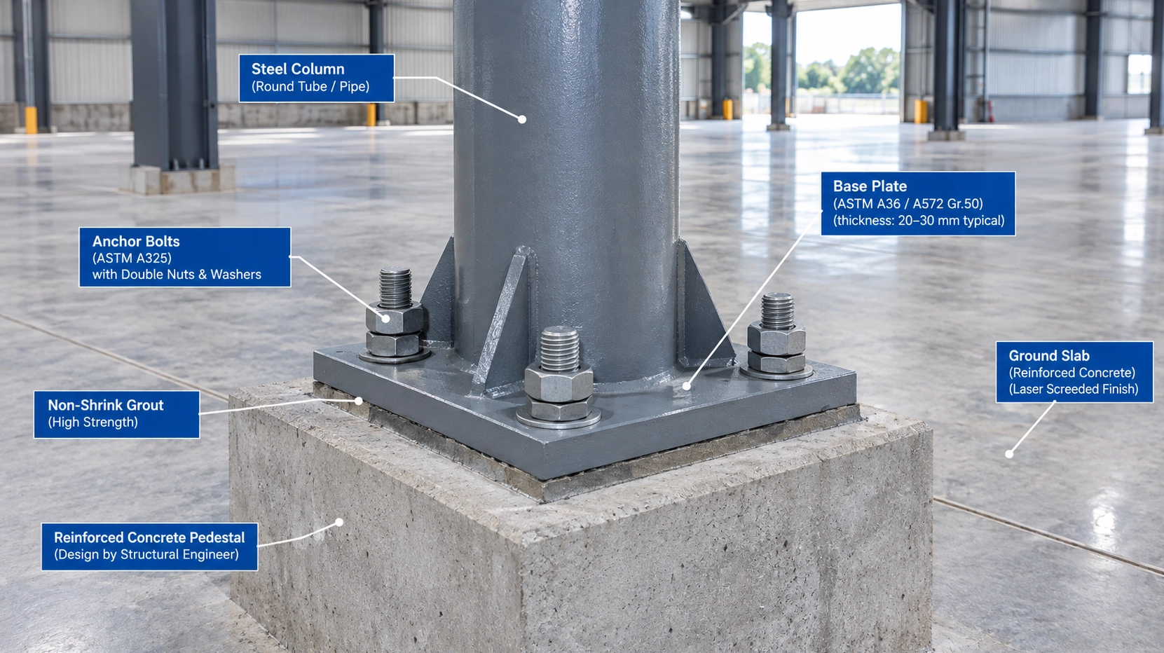
From an execution standpoint, multi-span foundations minimize structural steel and rebar detailing conflicts. Interior pinned base connections rely on compact two-bolt or four-bolt patterns detailed per AISC Design Guide 1 Section 2.3, using anchor bolts set to standard erection tolerances of ±3 mm per AISC Code of Standard Practice (AISC 303-16). Base plates cut on CNC plasma tables to ±0.5 mm tolerances install over non-shrink grout pads without interfering with congested top-mat footing rebar. Substructure rebar and excavation costs decrease by 30%–40%, saving $150,000–$250,000 USD on a 20,000 m² project while mitigating geotechnical risks in marginal soils.
Logistics Layout Synchronization: Embedding Columns into Flue Spaces
Logistics operators frequently specify clear-span buildings under the false assumption that interior columns disrupt material handling and reduce overall storage density. That assumption is obsolete. When structural engineers coordinate framing grids directly with the racking vendor during schematic design, interior columns disappear into non-working spaces. Achieving significant Multi-Span PEB Logistics Warehouse Cost Saving requires treating the building envelope and the intralogistics system as a single integrated assembly rather than two isolated packages.
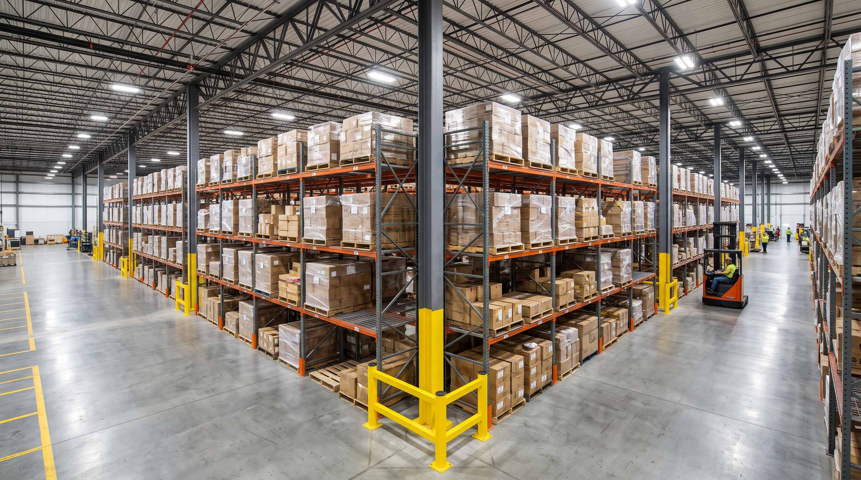
Standard selective and high-density racking configurations place pallet runs back-to-back, separated by a mandated flue space to satisfy fire sprinkler coverage under NFPA 13 guidelines. Interior columns placed inside 200mm–300mm back-to-back pallet flue spaces result in less than 0.5% lost pallet capacity. By sizing interior columns as slender built-up H-sections (ASTM A992 or Q355B) oriented with their strong axis parallel to the rack spine, the column flange fits completely within this longitudinal flue envelope. In narrow-flue layouts, the column displaces at most a single pallet position every 9 to 12 meters along that specific rack line. Across a 20,000 m² distribution center, net storage capacity retention exceeds 99.5%, while the primary structural framing weight drops by 25% to 35%.
Typical Bay Synchronization Detail (Plan View Schematic)
Longitudinal bay modules of 9m and 12m align directly with standard 2.7m pallet rack beam sections (3 to 4 rack bays per PEB bay). Intermediate 10m modules achieve the same alignment. Standard industrial racking relies on 2700mm clear beam spans designed to hold three 800×1200mm Euro-pallets or two 1000×1200mm industrial pallets with operational clearances. When the building's longitudinal column grid is set to an exact multiple of the rack section (including the 75mm to 100mm upright frame thickness), structural columns never drift into rack upright locations or working aisles.
Transverse structural spans must mirror standard racking modules and operating aisles:
- 2 × 30m layout: Optimized for wide-aisle counterbalance trucks (3.0m–3.5m aisles) across twin portal frames.
- 3 × 24m layout: Engineered for high-throughput reach truck operations (2.7m–3.0m aisles) with balanced bending moments across rafters.
- 4 × 20m layout: Designed for ultra-high-density automated storage and retrieval systems (ASRS) or wire-guided operations.
Under these layouts, aisle widths for reach trucks (2.7m–3.0m) and VNA wire-guided turrets (1.6m–1.8m) remain 100% unobstructed. Because all intermediate columns stay embedded in the rack line, material handling equipment maneuvers along clear paths with zero risk of structural column impact during high-speed picking.
Structural Framing and Floor Plate Synchronization Metrics
| Structural System | Transverse Span Module (m) | Longitudinal Bay (m) | Framing Steel Intensity (kg/m²) | Pallet Capacity Loss (%) | Primary Frame Cost ($/m²) |
|---|---|---|---|---|---|
| Clear-Span Rigid Portal | 1 × 60m | 9.0m | 46.5 – 54.0 | 0.00% | $58.00 – $68.00 |
| Multi-Span Twin Portal | 2 × 30m | 9.0m | 31.0 – 35.5 | 0.22% | $39.00 – $44.00 |
| Multi-Span Triple Portal | 3 × 24m | 10.8m | 27.5 – 31.0 | 0.35% | $34.50 – $39.00 |
| Multi-Span Quad Portal | 4 × 20m | 12.0m | 24.5 – 28.0 | 0.41% | $30.50 – $35.00 |
*Data based on 10.5m eave height, 0.45 kN/m² roof live load, and Q355B fabrication under AISC 360-16 specifications.
Fabrication and Erection Interfaces
Shop-floor fabrication accuracy directly controls the feasibility of flue-space column integration. Jinan XinQiao limits CNC plasma cutting tolerances on web and flange plates to ±0.5mm, welding built-up sections in accordance with AWS D1.1 using automatic submerged arc welding. All structural steel receives ISO 8501-1 Sa 2.5 abrasive blast cleaning, followed by an 80μm DFT zinc-rich epoxy primer to handle warehouse humidity cycles.
Anchor bolt embedment must be verified prior to slab placement. In accordance with AISC Design Guide 1 Section 2.3, column base plates require four-bolt patterns placed to a tolerance of ±3mm. Base plates are kept flush or countersunk into the slab depression, avoiding interference with rack baseplates and ensuring expansion anchors for rack uprights maintain required edge distances per ACI 318 Chapter 17. Structural engineering and warehouse operations provide a unified layout, saving up to 35% in framing steel with zero penalty to warehouse storage output.
Supply Chain & Erection Velocity: Container Nesting and Crane Optimization
Achieving maximum Multi-Span PEB Logistics Warehouse Cost Saving requires engineering structural members with the transport envelope and erection sequence in mind. Clear-span logistics facilities frequently specify plate girders with web depths between 1,400mm and 1,800mm to control mid-span deflections. These oversized members consume disproportionate cubic volume inside shipping containers and flatbed trailers. In contrast, optimized continuous multi-span frames use interior valley columns to limit rafter web depths to 600mm to 850mm. Fabricating these members from ASTM A572 Grade 50 (or Q355B) steel cut on multi-torch CNC plasma tables within ±0.5mm tolerances produces compact, high-capacity structural elements that streamline ocean transit and overland freight.
Container Nesting and Freight Optimization
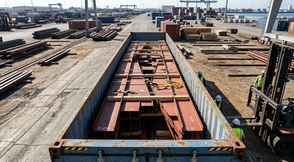
Standard 40-foot High Cube (40HC) ocean containers provide an internal height of 2,698mm and a door opening width of 2,340mm. When shipping rigid plate girders exceeding 1,400mm in depth, structural framing geometry prevents efficient packing, often limiting payload weights to 14 to 17 metric tons per box against a maximum allowable payload of 26.5 to 28 metric tons.
Multi-span framing designs bypass this penalty by utilizing tapered profiles. In our fabrication yard, paired rafter segments are bundled flange-to-flange in opposing orientations. Two tapered sections with depths tapering from 850mm at the haunch down to 450mm at the splice fit within a combined depth profile of under 1,350mm. This geometry allows dual-layer stacking with space remaining for cold-formed Z-purlins, structural pipe struts, and bracing hardware. Tapered rafter nesting reduces container shipping volume and overland freight costs by 15% to 20%, ensuring each container hits its maximum permissible payload limit before cube-out occurs.
| Shipping and Erection Metric | Heavy Clear-Span Plate Girder | Multi-Span Tapered PEB Frame | Operational Advantage |
|---|---|---|---|
| Primary Rafter Web Depth | 1,400mm – 1,800mm | 600mm – 850mm | 45% – 55% reduction in cross-sectional profile |
| Container Freight Utilization | 14 – 17 tons / 40HC box | 24 – 27 tons / 40HC box | Up to 60% higher density per container |
| Average Single Rafter Pick Weight | 9.5 – 14.0 metric tons | 2.8 – 4.2 metric tons | 65% reduction in hoisted mass |
| Required Crane Configuration | Dual 75 to 100-ton mobile cranes | Single 25 to 50-ton hydraulic crane | Eliminates engineered tandem lift permits |
| Dry-In Velocity (20,000 sqm facility) | 12 – 14 weeks | 8 – 9 weeks | 3 to 5 weeks schedule compression |
Crane Optimization and Field Erection Dynamics
On-site rigging operations directly impact the project schedule and site preliminaries. Heavy clear-span rafter assemblies necessitate dual-crane tandem lifts, requiring certified lift plans, dynamic load distribution monitors, and extensive crane pad civil works.
With multi-span PEB architecture, modular rafter assemblies span 20m to 24m between support points, reducing individual segment weights to 2.8 to 4.2 metric tons. Site crane requirements drop from dual 75 to 100 ton tandem cranes to standard 25 to 50 ton mobile cranes. A single 35-ton rough-terrain telescopic crane can hoist and place these components without repositioning mats or requiring multi-point outrigger stabilization platforms.
Connections are pre-detailed to AISC 360-16 specifications using ASTM A325 or ISO 4014 Grade 8.8 structural bolts in standard clearance holes. The lighter framing members permit ground pre-assembly of two-bay rafter pairs along with their bridging systems before lifting. The erection schedule is shortened by 3 to 5 weeks, lowering site preliminary expenses and accelerating rental revenue for the facility developer. Anchor bolts placed to a ±3mm tolerance eliminate field modifications, keeping erectors on a repeatable path from baseplate setting to dry-in.
Serviceability Deflection Limits & Global Code Compliance (AISC/MBMA, IS 800, Eurocode 3)
Achieving maximum Multi-Span PEB Logistics Warehouse Cost Saving requires evaluating serviceability limit states across international structural codes, including AISC 360-16 / MBMA 2018 (via AISC Design Guide 3), IS 800:2007 (Section 5.6, Table 6), and Eurocode 3 (EN 1993-1-1 read alongside EN 1990). Under standard roof live load (Lr) and snow load (S), standard codes prescribe rafter vertical deflection limits between L/180 and L/240, with total gravity load limits reaching L/120 to L/180.
In a wide 60m clear-span portal frame, meeting an L/180 deflection threshold permits up to 333mm of elastic mid-span sag under transient load. To prevent excessive ponding and cladding seam distortion, engineers must specify deep, stiff built-up I-sections. Rafter haunch depths regularly exceed 1,500mm to 1,750mm, with flange plates up to 25mm thick (ASTM A572 Gr 50 or Q355B). These oversized rafters encroach significantly on internal vertical clearances, raising the perimeter eave height and driving up foundation reaction costs.
Subdividing the building envelope into multi-span frames alters this deflection equation. Because elastic deflection under uniform loading is proportional to the span length to the fourth power (wL4 / 384EI), structural engineers evaluate serviceability criteria over individual modular sub-spans rather than the total building width. Allowable vertical deflection (L/180 to L/240) evaluated over 30m sub-spans reduces rafter deflections by up to 75% compared to a 60m clear span.
| Design Parameter / Code Criteria | 60m Clear-Span Portal Frame | 2 × 30m Multi-Span Rigid Frame | Engineering Impact / Cost Differential |
|---|---|---|---|
| AISC 360 / MBMA Deflection Limit (Lr) | L/240 (250mm max deflection) | L/240 (125mm max deflection) | 50% absolute deflection reduction |
| IS 800:2007 (Table 6) Live Load Limit | L/180 (333mm max deflection) | L/180 (166mm max deflection) | Stabilizes standing seam roof clips |
| Eurocode 3 (EN 1993-1-1 / EN 1990) | L/200 (300mm max deflection) | L/200 (150mm max deflection) | Prevents ponding instability risks |
| Typical Rafter Haunch Depth | 1,550mm – 1,750mm | 750mm – 900mm | Headroom reclaimed under eaves |
| Typical Flange Thickness (Q355B) | 20mm – 28mm | 10mm – 14mm | Eliminates multi-pass weld preheats |
| Typical Web Thickness | 10mm – 12mm | 6mm – 8mm | Standard automated SAW line sizing |
| Structural Steel Weight Index | 48 – 58 kg/m² | 27 – 34 kg/m² | 35% to 45% framing mass reduction |
By truncating sub-spans to 30m, rafter section depths drop from 1,600mm down to 800mm. This reduced rafter haunch depth reclaims 600mm to 850mm of vertical clear height under frame knees for extra pallet levels, directly unlocking an additional tier of racking for narrow-aisle logistics operations without raising building ridge elevations. Compliance with MBMA, AISC 360, IS 800, and Eurocode 3 is achieved with significantly lower plate thicknesses, which avoids heavy preheating protocols mandated by AWS D1.1 for plates over 20mm thick.
Introducing internal valley lines requires precise drainage engineering. Continuous internal valley gutters must manage storm events based on a minimum 100-year mean return interval. Valley gutters are fabricated from 3.0mm thick pre-galvanized or 304-grade stainless steel sheet, sloped at a minimum 1:200 toward internal downspouts. Internal valley columns also act as rigid collection corridors, integrating drop-out scuppers and siphonic rainwater downpipes adjacent to column flanges to preserve usable aisle dimensions.
In fabrication, multi-span components run through CNC plasma cutting with cut tolerances held to ±0.5 mm and web-to-flange junctions welded via automated submerged arc welding (SAW) per AWS D1.1 and EN 1090-2 Execution Class 3 (EXC3). Structural components receive Sa 2.5 shot blasting followed by an 80-micron dry film thickness (DFT) epoxy zinc-rich primer. Foundation anchor bolt clusters beneath internal rocker columns are placed within a ±3 mm tolerance, ensuring axial load transfer without inducing unanticipated prying moments at base plates.
Procurement & Value Engineering Matrix: Decision Framework for Industrial Developers
Industrial developers, real estate investment trusts (REITs), and EPC contractors routinely absorb unnecessary capital expenditures by misaligning structural framing typologies with internal material handling workflows. Achieving an optimal Multi-Span PEB Logistics Warehouse Cost Saving requires evaluating structural steel consumption directly against rack layout geometry and operational logistics velocity. Warehouses wider than 48m with racking storage achieve an average IRR improvement of 2.4% when utilizing multi-span framing. Clear-span systems should be strictly reserved for high-velocity cross-dock staging areas under 45m or non-racked bulk floor operations. When automated guided vehicles (AGVs) operate along unconstrained multidirectional pathways or when handling air cargo containers, clear spans eliminate spatial conflicts. Conversely, standard selective, reach-truck, and very narrow aisle (VNA) racking layouts absorb interior columns within back-to-back rack flue spaces with zero net loss in pallet capacity.
| Facility Application | Width Envelope | Optimal Framing Typology | Steel Consumption (kg/m²) | Foundation Concrete Volume (m³/bay) | Relative Structural Cost Index |
|---|---|---|---|---|---|
| Bulk Air Cargo / Hangar | 45m to 60m | Single Clear-Span Rigid Frame | 52 to 68 | 8.5 to 11.0 | 1.45 to 1.65 |
| Omni-AGV Cross-Dock | 36m to 48m | Single Clear-Span Rigid Frame | 42 to 55 | 6.5 to 8.2 | 1.25 to 1.40 |
| Regional Distribution Center | 60m to 96m | Multi-Span (2 × 30m to 3 × 32m) | 28 to 36 | 3.8 to 4.9 | 1.00 (Baseline) |
| High-Bay Selective Logistics | 96m to 144m | Multi-Span (4 × 24m to 4 × 36m) | 25 to 33 | 3.2 to 4.2 | 0.88 to 0.95 |
| Heavy Bulk Pallet Staging | > 120m | Multi-Span with Jack Beams | 29 to 37 | 4.0 to 5.1 | 0.98 to 1.05 |
PEB Procurement Guidelines and Value Engineering Guardrails
To protect project returns, procurement specifications must impose strict structural and fabrication parameters during the bidding phase:
- Rafter Knee Haunch Depth Cap: Tender specifications must cap rafter knee haunches at 950 mm using continuous multi-span geometry. Haunch depths exceeding 1,400 mm in unoptimized clear-span bids violate NFPA 13 clearance zones below automatic sprinklers and reduce top-tier racking elevations.
- Plate Thickness and Slenderness Controls: Built-up plates fabricated from ASTM A572 Grade 50 or GB/T 1591 Q355B steel must comply with slenderness limits defined in AISC 360-16 Table C-B4.1E. Bidding packages must establish a minimum web thickness of 6.0 mm and minimum flange thickness of 8.0 mm for all primary tapered frames. This standard eliminates heat-distortion oil-canning during automatic submerged arc welding (SAW) and prevents transport buckling.
- Foundation Kickout Envelope Verification: Structural tenders must specify maximum permissible column-base horizontal thrust reactions calculated per AISC Design Guide 1 Section 2.3. Clear-span rigid frames often generate foundation lateral thrusts exceeding 180 kN per base, necessitating massive grade beams and post-tensioned ties. In contrast, multi-span pinned-base interior columns lower these thrust values to under 35 kN, reducing foundation concrete volume by up to 40% under ACI 318-19 design parameters. Anchor bolt layouts must be held to a ±3 mm installation tolerance.
- Fabrication Tolerances and Surface Protection: Shop fabrication must enforce CNC plasma cutting tolerances of ±0.5 mm in accordance with EN 1090-2 Class 1 execution standards. All structural members require centrifugal abrasive blast cleaning to ISO 8501-1 Sa 2.5, coated with a two-component epoxy zinc-rich primer achieving a minimum 80 μm dry film thickness (DFT). All complete-joint-penetration (CJP) welds at rafter-to-column moment connections require ultrasonic testing per AWS D1.1.
- Weight Warranties: Contracts must incorporate an enforceable steel tonnage warranty. Fabricators must warrant that final engineered shop drawings will not exceed structural design takeoff weights by more than ±1.5%, insulating the developer from material creep during detailed connection design.
Conclusion & Core Structural Verdict
Core Structural Verdict
Moment-resisting haunch connections must satisfy AISC 360-16 and Design Guide 1 criteria. Foundation anchor rods must resolve lateral horizontal thrust via hairpin rebar or tie rods whenever base thrust exceeds 85 kN per footing.
One more thing
Direct collaboration between consulting engineers and production fabricators mitigates erection mismatches before components reach the foundation slab. Our senior engineering department conducts full constructability audits, verifying connection geometry, anchor bolt patterns, and weld classifications for every order. Before finalizing structural tenders or detailed drawings, consult our engineering desk for an industrial prefab steel warehouse technical review. We review your architectural layouts to ensure full compliance with EN 1090 and AISC 360 specifications while streamlining on-site assembly schedules.
References
Base Plate and Anchor Rod Design (Second Edition)
Fisher, J. M., & Kloiber, L. A. • American Institute of Steel Construction (2006)
Building Code Requirements for Structural Concrete (Chapter 17: Anchoring to Concrete)
American Concrete Institute (2019)
Standard Specification for Anchor Bolts, Steel, 36, 55, and 105-ksi Yield Strength
ASTM International (2020)
Code of Standard Practice for Steel Buildings and Bridges (Section 7.5: Anchor Rods and Foundation Bolting)
American Institute of Steel Construction (2022)
Eurocode 3: Design of steel structures — Part 1-8: Design of joints
European Committee for Standardization (CEN) (2005)
Eurocode 2: Design of concrete structures — Part 4: Design of fastenings for use in concrete
European Committee for Standardization (CEN) (2018)
Execution of steel structures and aluminium structures — Part 2: Technical requirements for steel structures
European Committee for Standardization (CEN) (2018)
Mechanical properties of fasteners made of carbon steel and alloy steel
International Organization for Standardization (2013)
Upstream Precision: How XinQiao Steel Eliminates Site Erection Headaches
The smoothest construction projects are those where the risk of field error is engineered out long before steel leaves the fabrication plant. When building in remote overseas destinations where specialized heavy equipment and certified rigging crews are expensive, prefabricated structural components must fit together seamlessly upon arrival.
Operating a 60,000 m² heavy industrial steel manufacturing facility in Taian, China, XinQiao Steel (Jinan XinQiao Steel Structure Co., Ltd.) solves overseas assembly challenges at the fabrication source: