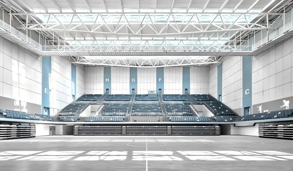
Insulated Roof & Wall Sandwich Panels: Prefab Steel Cladding Buyer's Guide
A comprehensive design guide for specifying structural insulated sandwich panels in prefabricated steel building walls. Compare PIR vs. mineral wool core mechanics, ASCE 7-22 wind span capacities, secondary cold-formed girt joint detailing, thermal bowing mitigation, and NFPA 285 / ASTM E119 fire-envelope compliance.

Specialist in industrial PEB detailing, building envelope structural mechanics, and overseas turnkey project delivery at Jinan XinQiao Steel Structure Co., Ltd.
Table of Contents & Quick Navigation
Engineering Fundamentals: Insulated Metal Panels in Prefabricated Steel Envelopes
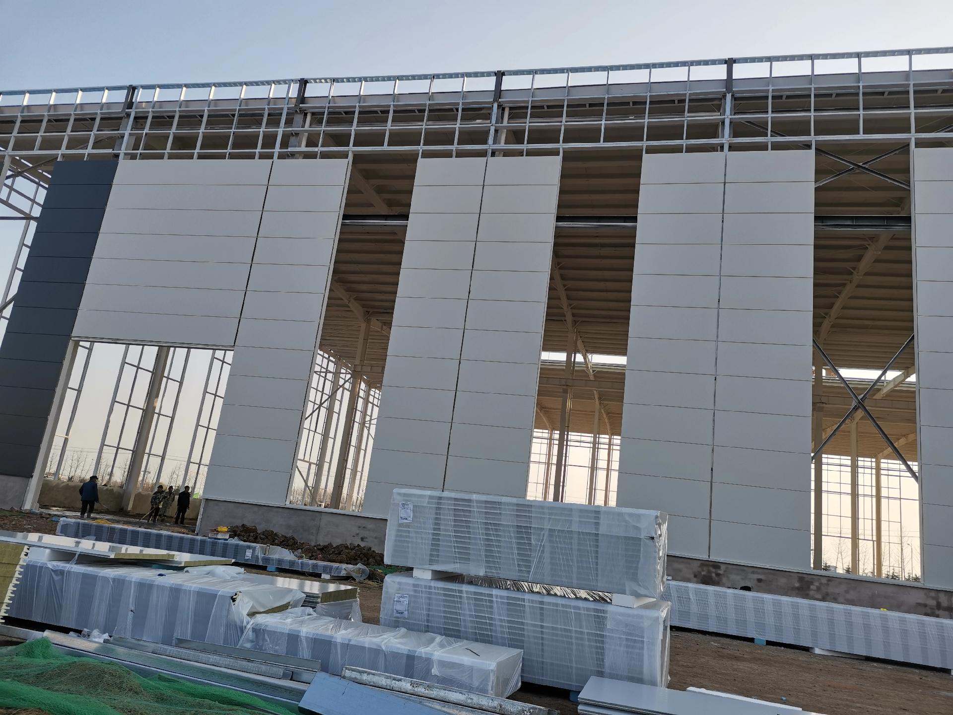
In heavy pre-engineered metal building (PEB) design, wall cladding is frequently mischaracterized as a non-structural architectural skin. Under CSI MasterFormat 07 42 13 (Insulated Metal Panels) and 13 34 19 (Metal Building Systems), insulated sandwich panels for prefabricated steel structure walls operate as engineered stressed-skin structural composites. Unlike modular container panels that use lightweight non-structural infill, or open architectural single-skin rainscreens that require secondary back-up framing, industrial insulated metal panels (IMPs) provide calculated structural resistance against lateral wind loads while establishing the complete exterior envelope.
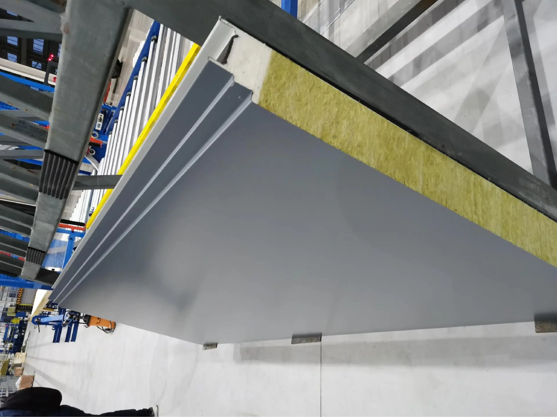
Structural sandwich performance relies on ASTM C393 flexural shear testing and ASTM E72 transverse chamber loading. In this composite configuration, two high-strength, thin steel facings handle pure axial tension and compression, separated by a rigid shear-transmitting core.
The assembly consists of an exterior facing fabricated from 24 ga (0.024 in / 0.60 mm) or 26 ga (0.018 in / 0.48 mm) structural steel per ASTM A792 (Grade 50, AZ50/AZ55 Galvalume) or ASTM A653 (G90 hot-dip galvanized). The interior facing is typically 26 ga Grade 33 steel coated with a USDA-compliant or anti-corrosive polyester finish. During continuous line manufacturing (tolerance control within ±1.0 mm panel width and ±2.0 mm length), a closed-cell polyisocyanurate (PIR) formulation or high-density lamella mineral wool (100 to 120 kg/m³) is bonded to both skins. Factory-injected autoadhesive polymer bonding achieves 100% surface contact, yielding flatwise tensile bond strengths exceeding 0.15 MPa and core shear strengths above 0.10 MPa per ASTM C273.
Traditional PEB wall construction requires a 5-layer field assembly: interior liner panel, cold-formed subgirts, fiberglass blanket or board insulation, a continuous vapor retarder film, and an exterior corrugated skin. This multi-trade approach presents significant thermal bridging across cold-formed Z-purlins and exposes unsealed fiberglass cavities to vapor condensation during field delays. In contrast, factory-manufactured IMPs consolidate thermal insulation, air barrier, vapor retarder, and exterior water shedding into a single factory-cured component.
| Engineering Parameter | Multi-Layer Built-Up Field Assembly | Single-Component Structural IMP |
|---|---|---|
| Primary Components | Liner + Subgirts + Batt + Vapor Foil + Outer Sheet | Exterior Steel + Rigid Core + Interior Steel |
| Assembly Operations | 4 to 5 distinct on-site trade passes | 1 single-pass crane/boom lift cycle |
| Air Infiltration Rate (ASTM E283) | 0.04 to 0.08 cfm/sq ft at 75 Pa | < 0.01 cfm/sq ft at 75 Pa |
| Water Penetration Resistance (ASTM E331) | 6.24 to 10.0 psf (field-joint dependent) | 15.0 psf static pressure (no leakage) |
| Thermal Bridging Loss (ASHRAE 90.1) | 35% to 55% reduction from nominal R-value | < 3% reduction (continuous insulation) |
| Erection Productivity Rate | 25 to 35 sq meters per crew-day | 90 to 130 sq meters per crew-day |
| Self-Weight per Unit Area | 14.5 to 19.0 kg/sq meter | 10.2 to 13.8 kg/sq meter (PIR, 75mm) |
| Structural Girt Spacing Capacity | 1.20 m to 1.50 m maximum center-to-center | 1.80 m to 2.40 m spans at 1.50 kPa wind load |
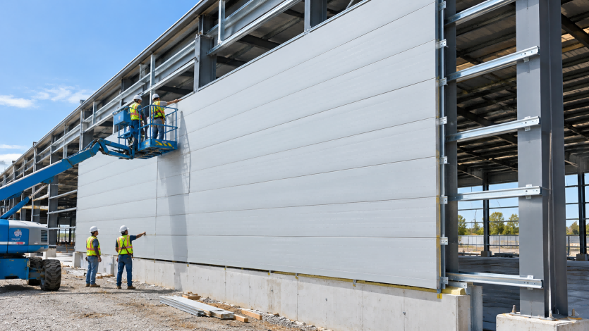
For PEB Project Directors and Principal Structural Engineers, specifying IMP envelopes optimizes secondary structural steel consumption. Because composite sandwich panels sustain higher positive and negative transverse wind pressures (tested per ASTM E1592) at mid-span, structural wall girt spacings can be expanded from 1.50 m up to 2.40 m. Fasteners (1/4-14 self-drilling carbon steel screws with EPDM washers) seat directly through panel tongue-and-groove joints into structural girt flanges (minimum 2.0 mm thickness, ASTM A1011 / Q355B), achieving immediate weather dry-in and lowering foundation dead-load requirements.
Structural Mechanics & Composite Action: Flexural Rigidity, Span Capacities, and Deflection Limits
The mechanical performance of insulated sandwich panels for prefabricated steel structure walls relies on full composite action between two high-tensile steel facings and a structural polymer core (polyisocyanurate or high-density structural mineral wool). Under transverse lateral wind loads, the structural mechanics follow sandwich beam theory rather than standard Euler-Bernoulli assumptions. Flexural tension and compression couples are resisted almost exclusively by the exterior and interior steel sheet skins, while the low-density core transmits transverse shear and stabilizes the thin facings against local micro-buckling and web wrinkling.
The composite flexural rigidity, denoted as (EI)eff, is derived by summing the discrete flexural contributions of the facings and the core:
Because the elastic modulus of the structural steel facing (Ef = 205 GPa or 29,000 ksi) is several orders of magnitude higher than that of the core (Ec ≈ 5 to 15 MPa for polyisocyanurate), the term Ec · Ic contributes less than 1% to overall flexural resistance and is disregarded in standard design calculations. Applying the parallel axis theorem where the facing area per unit panel width b is Af = b · tf and the distance between the facing centroids is d:
Transverse shear force V develops horizontal shear flow across the core cross-section, calculated via:
Because the core material exhibits a shear modulus Gc ranging from 350 to 550 psi (2.41 to 3.79 MPa), shear deformation cannot be omitted from deflection analyses. The total mid-span deflection Δtotal under uniformly distributed wind load w incorporates both flexural bending and core shear displacement:
Where Av = b · d represents the effective shear cross-sectional area.
Load Transfer to Cold-Formed Steel Framing
Lateral forces transfer from the sandwich panel to the cold-formed steel (CFS) structural framing (typically ASTM A653 Grade 50 Z-girts or C-channels with minimum yield strength Fy = 345 MPa and thickness 1.50 mm to 2.50 mm) through self-drilling carbon steel or 304/316 austenitic stainless steel fasteners.
Workshop detailing requires CNC pre-punching of CFS girt webs with slot tolerances within ±0.5 mm, whereas field erection allows structural frame alignment tolerances within ±3 mm over a 6-meter span. Fastener pull-out resistance, sheet pull-over (prying), and localized core crushing are designed in accordance with AISI S100 and EN 14509.
Transverse capacity is validated through full-scale ASTM E72 vacuum chamber transverse load testing and ASTM E1592 cyclic wind uplift verification.
Under ASCE 7-22 Components & Cladding (C&C) wind criteria, exterior building envelopes experience severe pressure variations between the wall field (Zone 4) and wall discontinuous corners (Zone 5), where corner vortex shedding significantly increases localized negative wind suction.
| ASCE 7-22 Wall Zone | Girt Spacing / Span (m) | Panel Thickness (mm) | Facing Gauge Ext/Int (mm) | Design Wind Suction (kN/m²) | Allowable Capacity (kN/m²) | Governing Failure Mode |
|---|---|---|---|---|---|---|
| Zone 4 (Field) | 1.80 | 75 | 0.50 / 0.40 | -1.45 | 2.10 | Core Shear Yielding |
| Zone 4 (Field) | 2.40 | 100 | 0.60 / 0.50 | -1.30 | 1.65 | Mid-span Deflection |
| Zone 5 (Corner) | 1.20 | 75 | 0.50 / 0.50 | -2.65 | 3.20 | Fastener Pull-Over |
| Zone 5 (Corner) | 1.50 | 100 | 0.60 / 0.50 | -2.40 | 2.85 | Intermediate Skin Wrinkling |
| Zone 5 (Corner) | 1.80 | 120 | 0.60 / 0.60 | -2.15 | 2.45 | Support Crushing / Wrinkling |
Multi-Span Static Indeterminacy and Skin Wrinkling
Continuous multi-span layouts (two-span or three-span arrangements over intermediate girts) reduce mid-span positive deflections compared to simply supported single spans. However, intermediate continuous supports introduce critical negative bending moments (Mneg = wL2 / 8 on a two-span configuration).
This negative moment places the internal steel skin in high local compression combined with localized contact bearing stress over the flange of the CFS girt. Under high negative suction, the exterior skin experiences severe compression over the support, making the exterior skin web wrinkling limit state govern structural panel sizing before core shear or fastener pullout thresholds are reached.
Serviceability Deflection Limits
Structural deflection thresholds must be strictly enforced based on the architectural functionality and structural interfaces of the facility.
| Deflection Threshold | Structural Application & Serviceability Objective | Minimum Core Thickness for 2.4m Span | Allowable Deflection at 2.4m Span (mm) |
|---|---|---|---|
| L / 180 | Standard industrial manufacturing warehouses and raw logistics shelters where secondary seal integrity is non-critical. | 75 mm | 13.3 mm |
| L / 240 | High-specification logistics and commercial facades; protects tongue-and-groove joint weatherproofing and prevents sealant failure under thermal cycles. | 100 mm | 10.0 mm |
| L / 360 | Panels interfacing directly with interior brittle finishes, internal drywall systems, or rigid masonry tie-ins to prevent structural cracking. | 120 mm | 6.7 mm |
Adherence to these limits ensures that panel joints retain their mechanical interlock, seal integrity remains air- and watertight under peak transverse pressure fluctuations, and secondary CFS framing is protected from prying forces caused by panel rotation.
Core Insulation Material Selection Matrix: PIR vs. Mineral Wool vs. PUR vs. EPS
When specifying insulated sandwich panels for prefabricated steel structure walls, structural engineers must treat the core material as an active structural web rather than merely passive insulation. In composite wall panel design, the core transfers longitudinal shear between the exterior and interior steel facings (typically 24 to 26 gage / 0.5 mm to 0.6 mm thick ASTM A653 or ASTM A792 sheet steel). This composite action prevents local face wrinkling and flexural buckling under severe transverse wind loads calculated per ASCE 7-22 or EN 1991-1-4. The four primary core formulations exhibit dramatically different mechanical densities, thermal resistances, and high-temperature failure mechanisms that directly dictate wall purlin spacing and building safety classifications.
Polyisocyanurate (PIR)
PIR is the engineering benchmark for cold-storage envelopes, processing plants, and high-efficiency pre-engineered industrial walls. PIR foam features an isocyanate-to-polyol index exceeding 250 (frequently reaching 300 to 350), promoting the formation of thermally stable, highly cross-linked isocyanurate ring structures.
- Thermal Performance: Achieves an initial R-value of R-8.0/in and an aged thermal resistance of R-7.0 to R-7.2 per inch at a 75°F mean temperature per ASTM C518 and ASTM C1303 long-term thermal resistance (LTTR) protocols.
- Mechanical Properties: Core density ranges between 2.0 and 2.5 pcf (32 to 40 kg/m³). Core shear strength reaches 20 to 28 psi (0.14 to 0.19 MPa), with a flatwise compressive strength of 20 to 25 psi (0.14 to 0.17 MPa) at 10% deformation.
- Reaction to Fire: As a thermoset plastic, PIR does not melt or drip under direct flame impingement. Instead, it forms a cohesive surface char layer that retards flame propagation, reliably meeting FM 4880 Class 1 and FM 4881 external wall approvals without requiring supplementary thermal barriers.
Mineral Wool (Stone Wool)
Mineral wool cores consist of high-density, spun basalt and metallurgical slag fibers oriented perpendicularly to the metal skins (lamella orientation) to provide maximum compressive and shear capacity.
- Thermal Performance: Yields R-3.8 to R-4.0 per inch, requiring thicker cross-sections to match PIR thermal envelopes.
- Mechanical Properties: Operates at a high density of 6.0 to 9.0 pcf (96 to 144 kg/m³). Because the fibrous matrix lacks inherent tensile-adhesive capacity to sheet steel, structural integrity relies entirely on continuous two-part polyurethane bonding adhesives applied at 200 to 250 g/m² on continuous automated laminator lines. Core shear strength is moderate at 10 to 15 psi (0.07 to 0.10 MPa).
- Reaction to Fire: Rated non-combustible per ASTM E136. Mineral wool panels provide the only pathway to achieving genuine 1-, 2-, and 3-hour fire-resistance ratings per ASTM E119 and UL 263 without adding internal drywall or gypsum boards to the prefabricated steel wall framing.
Polyurethane (PUR)
Standard rigid polyurethane foam represents an older thermoset chemistry with an isocyanate index typically between 100 and 150.
- Thermal Performance: Delivers an aged R-value of R-6.0 to R-6.5 per inch.
- Deficiencies: While PUR shares similar density (2.0 to 2.3 pcf) and shear values (18 to 24 psi) with PIR, its polymer backbone lacks the triisocyanurate ring structure. Under fire exposure, PUR experiences rapid thermal degradation, volatile gas emission, and lower char stability. In sustained thermal cycling conditions, PUR exhibits higher susceptibility to flame-retardant volatilization, leading to embrittlement and progressive delamination from the steel facings over extended building lifespans.
Expanded Polystyrene (EPS)
EPS is a closed-cell thermoplastic material fabricated by expanding polystyrene beads with pentane blowing agents.
- Thermal Performance: R-3.85 to R-4.0 per inch at 1.0 to 1.5 pcf (16 to 24 kg/m³) density.
- Catastrophic Failure Modes: EPS exhibits poor structural shear transfer (core shear strength rarely exceeds 6 to 9 psi), leading to excessive panel deflection under heavy suction loads. Thermally, EPS undergoes an irreversible phase change, softening and collapsing at approximately 200°F (93°C) and melting rapidly into a flammable liquid fuel source at 300°F (149°C). This rapid cavity collapse produces catastrophic delamination and fails NFPA 285 multi-story fire tests, making EPS unsuitable for non-combustible commercial envelopes and modern industrial prefabricated steel structures.
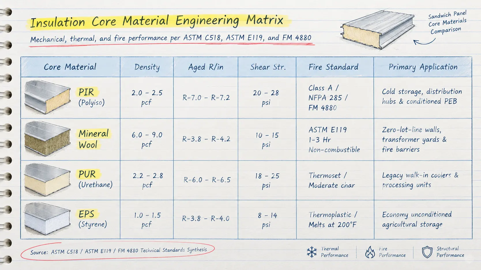
Table 1: Engineering Property and Performance Comparison Matrix for PIR and Mineral Wool versus PUR and EPS
| Engineering Property / Metric | Polyisocyanurate (PIR) | Mineral Wool (Stone Wool) | Polyurethane (PUR) | Expanded Polystyrene (EPS) |
|---|---|---|---|---|
| Nominal Core Density (pcf / kg/m³) | 2.0 - 2.5 / 32 - 40 | 6.0 - 9.0 / 96 - 144 | 2.0 - 2.3 / 32 - 37 | 1.0 - 1.5 / 16 - 24 |
| Aged Thermal Resistance (R-value/inch @ 75°F) | R-7.0 - R-7.2 | R-3.8 - R-4.0 | R-6.0 - R-6.5 | R-3.85 - R-4.0 |
| Core Shear Strength per ASTM C273 (psi / MPa) | 20 - 28 / 0.14 - 0.19 | 10 - 15 / 0.07 - 0.10 | 18 - 24 / 0.12 - 0.16 | 6 - 9 / 0.04 - 0.06 |
| Compressive Strength @ 10% Strain (psi / kPa) | 20 - 25 / 138 - 172 | 15 - 22 / 103 - 151 | 18 - 22 / 124 - 151 | 10 - 14 / 69 - 96 |
| Core Material Class | Thermoset polymer | Non-combustible mineral | Thermoset polymer | Thermoplastic polymer |
| High-Temperature Behavior | Surface charring, no melt | Sintering point > 1800°F | Scission, degraded char | Melts/collapses @ ~200°F |
| Combustibility Standard (ASTM E136) | Combustible (Core) | Non-Combustible | Combustible (Core) | Combustible (Core) |
| Fire Resistance Assembly Rating (ASTM E119) | 0 hours (Reaction only) | 1, 2, or 3 hours | 0 hours (Reaction only) | 0 hours (Fails NFPA 285) |
| Large-Scale Wall Approval (FM 4880 / NFPA 285) | Passes (Class 1) | Passes (Class 1) | Requires special additives | Fails standard assembly |
| Primary Structural Shear Transfer Mode | Direct chemical foam bond | Structural adhesive line | Direct chemical foam bond | Fusion/mechanical bond |
Structural and Envelope Integration
From a structural framing perspective, panel selection directly governs purlin and girt spacing on the pre-engineered building framework. Because PIR offers the highest shear strength (up to 28 psi) combined with low dead weight (roughly 2.2 to 2.8 psf for a 2-inch panel assembly), it allows engineers to maximize horizontal girt spans up to 8 or 10 feet (2.4 to 3.0 m) under standard 25 psf wind loads.
Conversely, when site property line clearances or occupancy classifications enforce an ASTM E119 fire-resistance rating, mineral wool is mandatory. Structural engineers must compensate for the substantial dead load increase (mineral wool panels typically weigh 5.5 to 8.0 psf for equivalent 4-inch, 2-hour assemblies) by specifying heavier structural steel cold-formed C or Z girts, reducing girt spacing to 4 or 6 feet (1.2 to 1.8 m), and using high-shear fastener patterns with larger diameter EPDM-bonded sealing washers to resist gravity-induced sagging and connection tear-out.
Here is what we would check first
Before finalizing secondary framing and panel envelopes, we evaluate connection detailing against dynamic wind uplift and dead load deflection criteria. Operating from our 60,000 sqm production plant, our automated CNC cutting lines maintain sub-millimeter fabrication tolerances in strict accordance with AISC 360 and EN 1090 execution standards. You can review our prefab steel warehouse engineering specifications to optimize frame spacing and cladding panel alignment before tender release.
Secondary Steel Framing Integration: Cold-Formed Girt Detailing and Thermal Bowing Mitigation
Directing load transfer between building cladding and secondary structural framing requires rigorous adherence to thin-walled steel mechanics. When securing insulated sandwich panels for prefabricated steel structure walls to secondary support systems, cold-formed secondary steel framing typically consists of 14 ga (0.068 in / 1.73 mm) to 16 ga (0.054 in / 1.37 mm) CFS Z or C girts fabricated from ASTM A1003 / A653 Grade 50 steel (yielding minimum Fy = 50 ksi / 345 MPa), or heavy structural ASTM A500 Grade C rectangular hollow sections (HSS).
The connection assembly must withstand cyclic wind suction forces mapped in ASCE 7-22 Chapter 30 (Components and Cladding). Under severe outward wind loads, three primary fastener limit states govern the load path per AISI S100 Section J4:
Governed by AISI S100 Section J4.4.1, calculated as Pnot = 0.85 · tc · d · Fu2, where tc is the girt flange thickness, d is fastener diameter, and Fu2 is the tensile strength of the girt steel.
Governed by AISI S100 Section J4.4.2, where the panel face sheet tears past the screw washer head. Fastener mechanical requirements mandate 1/4-14 self-drilling TEK structural screws with a minimum 1/2 in (12.7 mm) washer head diameter fitted with an integrated vulcanized EPDM seal to distribute localized bearing stress.
Repeated reverse-load cycles induce fatigue in the unthreaded shank of the fastener, necessitating grade-certified carbon steel screws with organic corrosion coatings passing 1,000-hour ASTM B117 salt-spray protocols.
Attachment Interface Mechanics: Concealed High-Shear Clips vs. Direct Through-Fastening
Specifying the panel-to-girt interface involves trade-offs between structural rigidity, thermal performance, and cyclic fatigue life.
| Parameter | Concealed High-Shear Clip System | Direct Through-Fastening System |
|---|---|---|
| Primary Hardware | 12 ga to 14 ga galvanized or austenitic stainless steel clips | 1/4-14 hex-head self-drilling carbon steel screws |
| Structural Mechanics | Fastener drives through clip base into girt flange; clip tongue embeds in panel female joint | Fastener penetrates exterior skin, polyisocyanurate core, and interior skin into girt |
| Thermal Bridging Impact | Zero point thermal bridges; fasteners isolated completely from conditioned space | Conductive metallic path penetrates panel; creates local condensation risks |
| ASCE 7-22 Wind Uplift ASD | 35 psf to 75 psf depending on clip spacing and girt gauge | 45 psf to 95 psf limited by interior sheet pullover capacity |
| Axial Slip Tolerance | Accommodates ± 1/4 in to 3/8 in panel thermal translation via clip slots | Negligible slip; thermal forces induce shear stress directly into screw shank |
| Secondary Framing Fatigue | Low; thermal movements dissipate through clip sliding surfaces | High; cyclic thermal rocking widens screw holes in 16 ga girts over time |
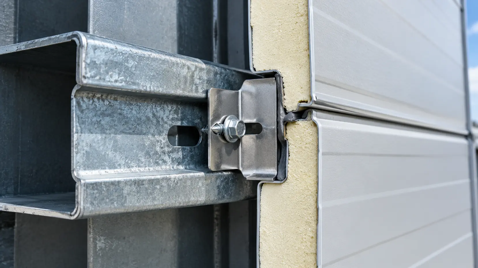
Concealed high-shear clip mechanics rely on heavy-gauge stainless or galvanized clips embedded in the joint female leg to eliminate thermal bridging while transferring transverse wind shears into the structural frame. Conversely, direct through-fastening locks the panel rigid, increasing cyclic fastener fatigue whenever large thermal swings occur.
Mathematical Derivation of Thermal Bowing Deflection
Insulated wall panels undergo severe differential thermal strain because the high-density polyisocyanurate core insulates the interior face from exterior climate extremes. Exterior facing temperature extremes on dark architectural colors reach 160°F to 180°F (71°C to 82°C) under high solar irradiation, while the interior facing remains stabilized at conditioned workspace temperatures of 68°F to 72°F (20°C to 22°C). This creates a temperature delta (ΔT) across the panel depth that often reaches 80°F (45°C) to 110°F (61°C).
Thermal strain differential (Δε) across the steel facings is expressed through the linear coefficient of thermal expansion for carbon steel (α = 12 × 10-6 m/m/°C or 6.7 × 10⁻⁶ in/in/°F):
Because the metallic skins are bonded to the rigid core material, this differential strain produces curvature (κ):
where d is the internal distance between the centroids of the exterior and interior sheet steel faces (effectively the panel nominal thickness). Integrating this curvature along a panel simply supported across secondary girt spacing L yields the maximum bowing deflection (wbow):
For a 3 in (76.2 mm) thick panel spanning L = 10 ft (3.05 m) under a design solar ΔT = 80°F (44.4°C), outward midpoint thermal bowing reaches:
Engineering Mitigation Detailing and Cold-Formed Girt Stability
Unrestrained thermal bowing deforms the panel outward, while rigid panel ends exert intense inward prying and rotational forces back onto the supporting secondary members. Mitigating these localized strains demands structural coordination across three detailing phases:
- Slotted Concealed Clips: Engineers must detail panel retention clips with horizontal or vertical elongation slots providing ± 1/4 in to 3/8 in (6.35 mm to 9.5 mm) movement capacity. Fasteners are driven to predetermined torque specifications (typically 45 to 60 in-lbs) to avoid clamping the clip base plate flat against the girt, ensuring axial slip along the slot during mid-afternoon solar expansion.
- Double-Girt Expansion Breaks: Continuous wall runs require structural relief joints at 40 ft (12.2 m) structural column bays. Rather than spanning panels across building expansion gaps, detail two separate lines of cold-formed girts separated by a 1 in to 2 in expansion gap. The panel run terminates on the first girt line and restarts on the second, capping the seam with an exterior flexible architectural flashing backed by closed-cell polyethylene foam backer rod and low-modulus silicone sealant.
- CFS Girt Flange Torsional Bracing and Web Crippling: Panel thermal thrust acting eccentrically on single-span Z-girt outer flanges produces coupled bending and torsion. Design the girts under AISI S100 Section C3.4 and C3.5 to prevent flange rotational buckling and unbraced web crippling. Provide anti-roll torsional sleeve struts or direct diagonal bridging connected to the primary structural column rafters at mid-span intervals.
During factory fabrication and field erection, maintaining secondary framing alignment tolerances is critical. Secondary girt face planes must not deviate more than ± 1/8 in (3.18 mm) across any 20 ft span to prevent locking panel joint tongues. Girt structural tubes and cold-formed sections must receive Sa 2.5 shot blast surface treatment followed by an 80-micron dry film thickness (DFT) epoxy zinc-rich primer coating, shielding fastener penetration zones from long-term interstitial moisture entrapment.
Building Code Mandates, Fire Safety (NFPA 285 / ASTM E119), and Thermal Envelope Compliance
Designing building envelopes with insulated sandwich panels for prefabricated steel structure walls requires balancing structural resistance with thermal and fire performance. Exterior wall assemblies must satisfy the weather-resistance mandates of International Building Code (IBC) Chapter 14 alongside the combustible material provisions of IBC Chapter 26 Section 2603. Because polyisocyanurate (PIR) and polyurethane (PUR) cores are classified as foam plastic insulation, IBC Section 2603.5 requires exterior non-load-bearing wall assemblies installed on Type I through Type IV construction to prove multi-story fire performance through intermediate-scale testing under NFPA 285.
Vertical & Lateral Limits
- Vertical Spread Cap: ≤ 10 ft (3.05 m) above window header
- Lateral Spread Cap: ≤ 5 ft (1.52 m) from window centerline
- Exterior Facing: ≥ 26 ga (0.48 mm) Steel ASTM A653
- Cavity Edge Protection: Mineral Wool Backer (4.0–6.0 lb/cu ft)
NFPA 285 compliance criteria mandate that vertical flame propagation cannot extend 10 ft or higher above the window opening header, and lateral flame spread must remain within 5 ft of the vertical centerline of the window opening. Meeting these thresholds requires careful detailing of panel geometry and secondary accessories. The exterior steel facing must maintain a minimum base metal thickness of 26 gauge (0.018 inch / 0.48 mm), though heavy-industrial framing often demands 24 gauge (0.024 inch / 0.60 mm) per ASTM A653 or ASTM A792 to prevent localized burn-through. Continuous, non-skinning butyl joint sealants must be applied on the warm-side interior interlock of the tongue-and-groove profile to starve the core of oxygen during exterior flame impingement. Perimeter flashings around window and door penetrations must be fabricated from minimum 20-gauge galvanized steel sheet and packed with non-combustible mineral wool backer (nominal density 4.0 to 6.0 lb/cu ft) to encapsulate exposed foam edges and prevent internal cavity ignition.
Zero-lot-line industrial developments, property-line fire separations, and high-hazard manufacturing divisions require calibrated hourly fire-resistance ratings under ASTM E119 and UL 263. Standard foam plastic IMPs cannot serve as rated firewalls because the organic polymer core decomposes at elevated temperatures. For these conditions, structural mineral wool core sandwich panels achieve certified 1-hour, 2-hour, and 3-hour fire-endurance assembly ratings. The mineral wool cores, composed of basalt rock fibers bonded perpendicular to the steel facings at densities between 6.5 and 8.5 lb/cu ft, resist temperatures above 1,800 degrees Fahrenheit without releasing structural integrity or propagating fire between property lines.
| Assembly Wall Configuration | Core Material and Density | ASTM E119 / UL 263 Rating | Nominal Thickness | Assembly Weight |
|---|---|---|---|---|
| Standard PIR Cold Storage Panel | Polyisocyanurate (2.2 lb/cu ft) | Non-rated (NFPA 285 compliant) | 3.0 in (76 mm) | 2.65 lb/sq ft |
| Heavy Industrial PIR Exterior Panel | Polyisocyanurate (2.4 lb/cu ft) | Non-rated (NFPA 285 compliant) | 4.0 in (102 mm) | 2.88 lb/sq ft |
| Fire-Barrier Mineral Wool Assembly | Lamella Basalt Rock (7.0 lb/cu ft) | 1-Hour Fire Endurance | 4.0 in (102 mm) | 4.75 lb/sq ft |
| Zero-Lot-Line Separation Wall | Lamella Basalt Rock (7.5 lb/cu ft) | 2-Hour Fire Endurance | 6.0 in (152 mm) | 6.42 lb/sq ft |
| Heavy Plant Boundary Firewall | Lamella Basalt Rock (8.2 lb/cu ft) | 3-Hour Fire Endurance | 8.0 in (203 mm) | 8.10 lb/sq ft |
Industrial property risk insurers require third-party verification beyond baseline municipal codes. FM Global 4880 Class 1 fire ratings certify that insulated wall assemblies resist internal fire propagation without contributing fuel, assessed through 25-ft and 50-ft corner test protocols. For envelope integrity under natural hazards, FM Global 4881 approval evaluates exterior wall assemblies against severe windstorm and hail conditions. This program subjects the panels to 10,000 cycles of dynamic pressure testing up to design pressures of ± 120 psf, combined with large missile impact testing (a 9-lb 2x4 lumber projectile traveling at 50 ft/s) to ensure the facings do not disengage from the sub-framing girts.
Thermal compliance under ASHRAE 90.1-2022 and IECC Chapter 4 requires continuous insulation (ci) that controls thermal bridging through structural framing members. Building codes dictate opaque wall assembly U-factors ranging from U-0.036 to U-0.048 across Climate Zones 1 through 8. Traditional field-assembled walls rely on fiberglass batts stuffed between cold-formed steel (CFS) girts; the steel members act as severe thermal bridges, causing a 45% to 55% derating between the installed assembly R-value and the nominal insulation rating.
| Wall Envelope System | Nominal Material R-Value | Thermal Bridging Derating | Effective Installed R-Value | Overall Assembly U-Factor | ASHRAE 90.1-2022 Compliance Status |
|---|---|---|---|---|---|
| 6-in CFS Girt + R-19 Fiberglass Batt | R-19.0 hr-ft²-F/Btu | 52% Performance Loss | R-9.1 hr-ft²-F/Btu | U-0.110 Btu/hr-ft²-F | Non-compliant (All Zones) |
| 8-in CFS Girt + R-25 Fiberglass Batt | R-25.0 hr-ft²-F/Btu | 48% Performance Loss | R-13.0 hr-ft²-F/Btu | U-0.077 Btu/hr-ft²-F | Non-compliant (All Zones) |
| 2.5-in PIR Continuous IMP Assembly | R-18.0 hr-ft²-F/Btu | 3% Joint Loss | R-17.5 hr-ft²-F/Btu | U-0.057 Btu/hr-ft²-F | Compliant (Zones 1-3) |
| 3.0-in PIR Continuous IMP Assembly | R-22.2 hr-ft²-F/Btu | 3% Joint Loss | R-21.5 hr-ft²-F/Btu | U-0.046 Btu/hr-ft²-F | Compliant (Zones 1-5) |
| 4.0-in PIR Continuous IMP Assembly | R-30.0 hr-ft²-F/Btu | 2% Joint Loss | R-29.4 hr-ft²-F/Btu | U-0.034 Btu/hr-ft²-F | Compliant (Zones 1-8) |
| 6.0-in Mineral Wool IMP Assembly | R-24.0 hr-ft²-F/Btu | 4% Fastener Loss | R-23.0 hr-ft²-F/Btu | U-0.043 Btu/hr-ft²-F | Compliant (Zones 1-6) |
Because insulated metal panel assemblies mount to the exterior face of structural framing via concealed clips or through-fasteners with thermal-break EPDM isolation washers, they eliminate thermal bridging across the building envelope. Factory-controlled production ensures that the rigid PIR or lamella mineral wool core forms an uninterrupted thermal envelope, retaining 95% to 98% of its nominal R-value under steady-state operating conditions.
To achieve these verified values on site, the underlying structural steel support system must meet strict erection tolerances. Structural girt out-of-plane deviation must not exceed L/240 or 1/4 inch (6.4 mm) over any 10-ft span per AISC Code of Standard Practice Section 7.13. Fastener installation requires calibrated clutch-driven screwdrivers running at 1,800 to 2,500 RPM to seat fasteners squarely against the structural girt without crushing the steel skin or depressing the tongue-and-groove joint profile, preserving factory air- and water-tightness certifications.
Joint Mechanics, Hygrothermal Performance, and Air-Vapor Barrier Continuity
The building envelope integrity of insulated sandwich panels for prefabricated steel structure walls depends on the micro-geometry of the interlocking panel edges. In high-performance industrial construction, basic single tongue-and-groove joints fail to provide adequate safeguards against air infiltration and vapor diffusion under cyclic wind pressures. Modern envelope engineering mandates an interlocking double tongue-and-groove joint profile with an integral capillary break cavity. This offset geometry interrupts the continuous capillary path, neutralizing wind-driven pressure differentials and preventing moisture siphoning across the joint interface.
Air and vapor barrier continuity requires non-skinning polyisobutylene (butyl) mastic sealant meeting AAMA 809.2 specifications. Factory-applied sealant ribbons ensure volumetric consistency (±0.5 mm bead tolerance), whereas field-applied butyl requires strict oversight to avoid bead discontinuity, skips, or contamination by workshop dust. From a hygrothermal standpoint, the primary vapor seal must sit on the warm-in-winter interior side of the joint tongue. Positioning the primary air-vapor barrier on the interior face prevents warm, high-humidity internal air from migrating into the joint cavity. If moisture breaches the warm envelope, it contacts the cold exterior sheet during winter conditions, precipitating immediate interstitial condensation.
| Joint Configuration | Sealant Chemistry and Placement | Air Infiltration Rate (ASTM E283 at 75 Pa) | Static Water Penetration (ASTM E331 at 575 Pa) | Interstitial Dew Point Control | Secondary Framing Isolation Method |
|---|---|---|---|---|---|
| Standard Single Tongue-and-Groove | Field-applied polyurethane bead on exterior leg | 0.12 cfm/sq ft (0.60 L/s per sq m) | Leakage observed at 6.24 psf (300 Pa) | High risk of condensation behind exterior skin | Bare steel direct bearing, accelerated corrosion |
| Double Tongue-and-Groove Offset | Dual factory-extruded AAMA 809.2 butyl beads (interior and exterior) | 0.02 cfm/sq ft (0.10 L/s per sq m) | Zero water penetration at 12.0 psf (575 Pa) | Absolute containment within continuous core | Closed-cell EPDM thermal isolator strip (3 mm) |
| Deep Shiplap with Capillary Siphon Groove | Factory butyl at interior tongue, field-applied neutral silicone at rainscreen | 0.04 cfm/sq ft (0.20 L/s per sq m) | Zero water penetration at 12.0 psf (575 Pa) | Dew point isolated to core center third | Factory-applied adhesive foam tape along Z-girt |
Rigorous physical testing validates these joint assemblies against severe atmospheric loads. Under ASTM E283, structural wall assemblies must demonstrate an air leakage threshold of 0.06 cfm/sq ft (0.30 L/s per sq m) or lower under a differential pressure of 1.57 psf (75 Pa). Dynamic and static water penetration resistance, validated under ASTM E331, requires zero water penetration across the joint plane under a continuous static water spray at a test pressure of 12.0 psf (575 Pa). These values ensure that exterior driving rain cannot bypass the secondary drainage plane of the joint profile.
WUFI hygrothermal modeling confirms the stability of this multi-barrier approach across multi-year seasonal cycles. Transient one-dimensional and two-dimensional moisture transport simulations show that when the warm-side interior vapor seal remains intact, the condensation isotherm (dew point) sits entirely within the hydrophobic polyisocyanurate (PIR) or stone wool core matrix. Because the core material maintains an ultra-low closed-cell vapor permeability, vapor cannot condense into free water.
This thermal break continuity prevents galvanic corrosion and concealed rust at cold-formed Z-girt flanges. Without continuous vapor sealing and joint-to-girt thermal break isolation tape (such as closed-cell EPDM or high-density cross-linked polyethylene), thermal bridges lower the structural steel surface temperature below the local dew point. Liquid condensate then accumulates along the hidden interface between the inner steel panel skin and the zinc-coated ASTM A653 Grade 50 (or Q355B) secondary cold-formed framing, causing premature section loss and structural degradation long before rust appears on visible surfaces.
Procurement, Life-Cycle Economics, and CSI MasterFormat Specification Guide
Procurement teams frequently miscalculate exterior envelope expenditures by evaluating factory material pricing in isolation rather than analyzing fully burdened, installed total cost of ownership (TCO). Specifying insulated sandwich panels for prefabricated steel structure walls eliminates the multi-tier contractor overhead common to conventional construction. A field-assembled, multi-trade built-up metal wall system requires five distinct layers: an interior liner panel, an elastomeric vapor retarder, structural hat-channel sub-girts, cavity insulation (mineral wool or fiberglass blankets), and an exterior corrugated weather screen. This assembly demands four separate trade mobilizations, extensive staging footprints, and prolonged perimeter scaffolding. Consequently, the installed cost for built-up field assemblies escalates to $28 to $44 per square foot across multiple mechanical, framing, and insulation contracts. In contrast, high-performance polyisocyanurate (PIR) insulated metal panels (IMPs) carry an installed cost of $22 to $35 per square foot, combining all five performance layers into a single factory-engineered component installed by one certified crew.
Schedule Compression and Operational Revenue
The decisive economic metric in industrial envelope procurement is critical-path schedule compression. Field crews erect continuous-span IMPs in a single pass, establishing immediate weather-tightness, exterior architectural cladding, code-compliant vapor barrier continuity, and high thermal resistance (aged R-8 per inch of core).
Replacing sequential trade installations with single-pass panel erection yields a 40% to 50% reduction in exterior envelope dry-in duration. On a 120,000-square-foot industrial warehouse or cold-storage distribution hub, this schedule reduction returns 6 to 10 weeks of building access to general contractors. Conditioned slab curing, mechanical and electrical rough-ins, process piping drops, and switchgear energization proceed months earlier than scheduled with built-up walls, eliminating owner carrying charges and cutting project general conditions overhead.
Pre-Installation Secondary Framing Tolerances
Because insulated metal panels function as rigid composite structural beams, they cannot yield or deform to absorb erratic erection errors in structural steel. Erector attempts to draw out-of-plane framing members to the panel face using heavy fastener torque invariably cause micro-cracking of the core, panel delamination, joint seal displacement, and visible optical oil canning. Prior to panel offloading, structural engineers and site superintendents must enforce secondary structural alignment per the AISC Code of Standard Practice (AISC 303-16) and MBMA Common Industry Practices:
- Secondary cold-formed girt alignment: Out-of-plane deviation of structural girts across adjacent structural spans must not exceed L/600, with an absolute hard limit of 3/8 in (9.5 mm) deviation over any 20 ft (6.1 m) continuous span.
- Secondary flange rotation: Structural cold-formed Z-purlins or C-channels must sit plumb; cross-flange rotational deviation must stay within plus or minus 1.5 degrees of true perpendicularity relative to the incoming panel interior face.
- Bearing support width: Intermediate structural girts require a minimum bearing width of 2.0 in (50 mm), and end-lap connections require a minimum bearing flat of 3.0 in (75 mm) to prevent web-crippling of the interior facing sheet under design suction loads.
CSI MasterFormat 07 42 13 Contract Specification Checklist
To prevent value-engineering shortcuts and ensure envelope performance over a 40-year design life, incorporate the following enforceable language into CSI Section 07 42 13 (Metal Wall Panels):
- Steel Metallurgy and Gages: Exterior face shall be minimum 24 AWG (0.60 mm) structural steel conforming to ASTM A653 structural quality Grade 33 or Grade 50, with a hot-dip galvanized coating of minimum G90 (Z275) or AZ50 Galvalume per ASTM A792. Interior face shall be minimum 26 AWG (0.48 mm) roll-formed steel with light plank profile.
- Architectural Fluoropolymer Finishes: Exterior coating system shall be a factory-applied, 1.0 mil nominal dry film thickness (DFT) 70% PVDF (polyvinylidene fluoride) resin system (Kynar 500 or Hylar 5000) meeting AAMA 2605 performance benchmarks. Finish must carry a 40-year non-prorated warranty covering color fade (less than 5 Delta E Hunter units per ASTM D2244) and chalk resistance (rating not less than 8 per ASTM D4214).
- Structural Fasteners: All concealed clips and face-fasteners shall be 300-series austenitic stainless steel self-drilling screws equipped with integral vulcanized EPDM sealing washers. Zinc-plated carbon steel fasteners are rejected for exterior marine or high-humidity interior service.
- Sealant Continuity: Factory-applied, non-skinning polyisobutylene or butyl mastic sealant complying with AAMA 809.2 and ASTM C919 must be applied continuously along the interior dry-side tongue-and-groove joint profile to maintain unyielding vapor barrier integrity.
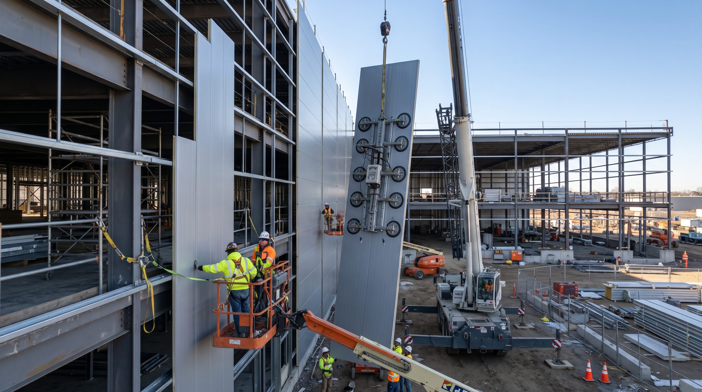
- Vacuum Lifting Equipment Protocols: Erection subcontractor must utilize multi-pad, dual-circuit vacuum lifters engineered specifically for dynamic wind-load handling during crane picks. Mechanical perimeter clamps or friction slings that crush interlocking tongue-and-groove joint profiles are forbidden.
- Field Quality Verification: Erection sign-off requires field-assembled mock-up water penetration testing per AAMA 501.2 (no uncontrolled water penetration at 25 to 30 psi nozzle pressure). Exterior envelope commissioning requires calibrated infrared thermographic imaging per ASTM C1060 under an interior-to-exterior differential temperature (Delta T) of at least 18 degrees Fahrenheit to identify unseated joints, thermal bypasses, or compressed core insulation.
Table 2: Life-Cycle Economics, Schedule, and Envelope Performance Comparison: IMP vs. Multi-Trade Built-Up System
| Performance Metric | Polyisocyanurate (PIR) IMP System | Multi-Trade Built-Up Wall System |
|---|---|---|
| Installed Total Cost of Ownership ($/sq ft) | $22 to $35 per sq ft | $28 to $44 per sq ft |
| Separate Subcontract Trades Required | 1 trade (certified envelope erector) | 4 trades (framing, sheet, insul., caulking) |
| Wall Installation Velocity (sq ft/crew/day) | 1,800 to 2,500 sq ft/day | 600 to 900 sq ft/day |
| Schedule Reduction to Complete Building Dry-In | 40% to 50% duration reduction | Baseline schedule reference duration |
| Whole-Envelope Air Infiltration (ASTM E283) | < 0.01 cfm/sq ft at 1.57 psf | 0.06 to 0.12 cfm/sq ft at 1.57 psf |
| Secondary Framing Alignment Tolerance | Strict: L/600, max 3/8 in over 20 ft span | Moderate: L/360, max 3/4 in over 20 ft span |
| On-Site Erection Lifting Equipment | Dynamic dual-circuit vacuum beam lifters | Manual hoist lines, staging, scissor lifts |
| Field Quality Acceptance Testing | AAMA 501.2 water spray, ASTM C1060 IR | Visual check, spot seam smoke testing |
| Exterior Finish Longevity and Warranty | 40-year non-prorated AAMA 2605 PVDF | 20 to 25-year prorated SMP / polyester |
| 30-Year Operating & Maintenance Cost | Low (washdowns, localized seal check) | High (fastener back-out, sagged batts) |
Conclusion
One more thing
Direct collaboration between consulting engineers and production fabricators mitigates erection mismatches before cladding and structural components reach the foundation slab. Our senior engineering department conducts full constructability audits, verifying connection geometry, slotted clip movement, wind load spans, and fire envelope classifications. Explore our architectural and industrial roofing & wall sandwich panels product line, or submit your architectural elevations for an automated take-off review.
References
Base Plate and Anchor Rod Design (Second Edition)
Fisher, J. M., & Kloiber, L. A. • American Institute of Steel Construction (2006)
Building Code Requirements for Structural Concrete (Chapter 17: Anchoring to Concrete)
American Concrete Institute (2019)
Standard Specification for Anchor Bolts, Steel, 36, 55, and 105-ksi Yield Strength
ASTM International (2020)
Code of Standard Practice for Steel Buildings and Bridges (Section 7.5: Anchor Rods and Foundation Bolting)
American Institute of Steel Construction (2022)
Eurocode 3: Design of steel structures — Part 1-8: Design of joints
European Committee for Standardization (CEN) (2005)
Eurocode 2: Design of concrete structures — Part 4: Design of fastenings for use in concrete
European Committee for Standardization (CEN) (2018)
Execution of steel structures and aluminium structures — Part 2: Technical requirements for steel structures
European Committee for Standardization (CEN) (2018)
Mechanical properties of fasteners made of carbon steel and alloy steel
International Organization for Standardization (2013)
Upstream Precision: How XinQiao Steel Eliminates Site Erection Headaches
The smoothest construction projects are those where the risk of field error is engineered out long before steel leaves the fabrication plant. When building in remote overseas destinations where specialized heavy equipment and certified rigging crews are expensive, prefabricated structural components must fit together seamlessly upon arrival.
Operating a 60,000 m² heavy industrial steel manufacturing facility in Taian, China, XinQiao Steel (Jinan XinQiao Steel Structure Co., Ltd.) solves overseas assembly challenges at the fabrication source: