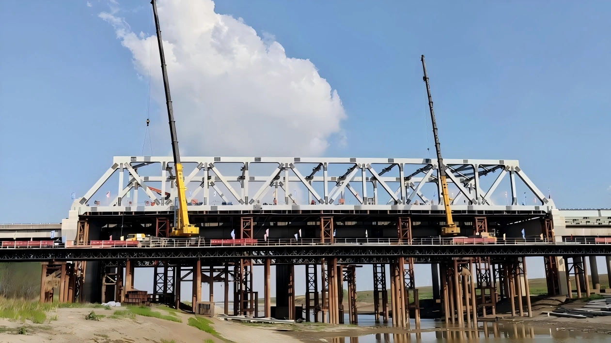
Large Clear-Span Prefabricated Steel Sports Stadium: Structural Design & Buyer's Guide
An authoritative B2B engineering and procurement guide to large span prefabricated steel structure sports stadium systems. Evaluate 3D tubular space trusses, curved CHS pipe cantilevers, and prestressed cable-dome networks across AISC 360-16 and Eurocode 3 design standards, node mechanics, ISO 12944 corrosion protection, container logistics, heavy strand-jacking erection, and turnkey Capex budgets.

Specialist in industrial PEB detailing, building envelope structural mechanics, and overseas turnkey project delivery at Jinan XinQiao Steel Structure Co., Ltd.
Table of Contents & Quick Navigation
Executive Overview: Engineering Demands of Large-Span Stadium Architecture
A modern large span prefabricated steel structure sports stadium represents one of the most demanding disciplines in structural engineering. These facilities require unobstructed column-free zones spanning from 60 meters to well over 200 meters to ensure sightline compliance per FIFA and Olympic athletic guidelines. At these dimensions, self-weight drives structural sizing. The dead-to-live load ratio shifts drastically compared to standard commercial frames, demanding advanced structural typologies that balance strength, self-weight, and aerodynamic performance.
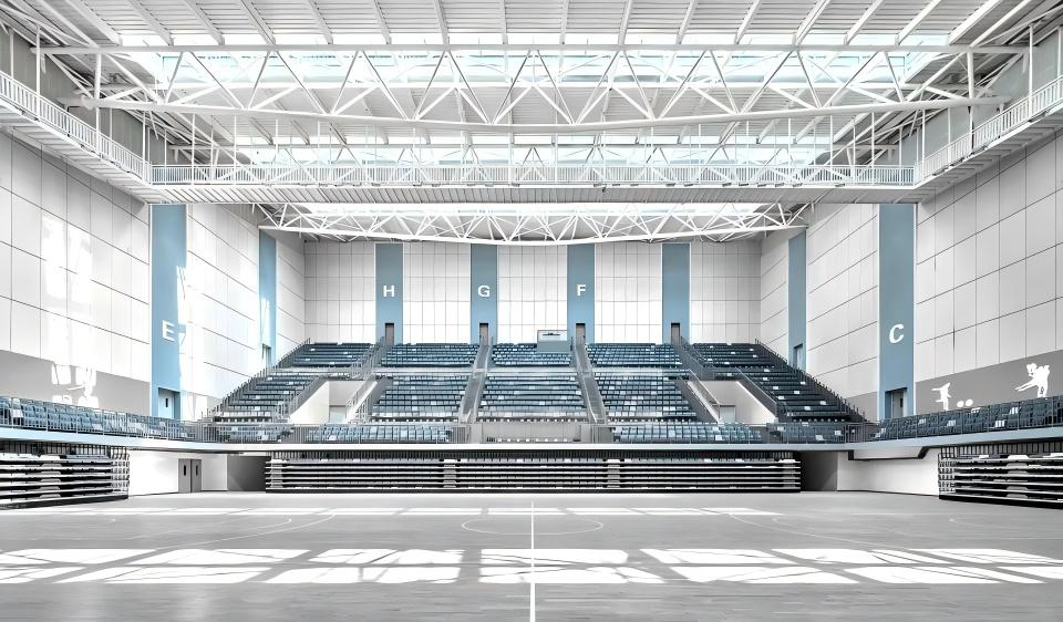
Engineering sports arena roofs over 60 meters requires solving four coupled structural failure modes:
- Non-linear Geometric Instability: Asymmetrical snow loads, thermal gradients, and unbalanced service loads induce second-order (P-Δ and P-δ) deflections that trigger local buckling in primary compression members before yield stress is reached.
- Dynamic Aerodynamic Uplift: Large-span cantilevered and suspended canopies behave as lightweight aerodynamic foils. Wind tunnel simulations per ASCE 7-22 or EN 1991-1-4 consistently show that localized suction peaks exceed gravity dead loads, reversing stress paths from tension to compression across bottom chord truss members.
- Crowd-Induced Resonance: Synchronized rhythmic human movement generates vertical and horizontal dynamic forces. Structural floors and grandstand integration frames must maintain fundamental natural frequencies outside critical excitation bands (typically above 3.5 Hz for vertical modes and 1.5 Hz for lateral modes) to comply with ISO 10137 and AISC Design Guide 11 vibration thresholds.
- Thermal Kinematics: Expansive roof diaphragms experience substantial volumetric movement across seasonal thermal differentials (ΔT ≥ 45°C), generating massive internal forces at rigid support boundaries unless accommodated via low-friction spherical structural bearings.
Traditional cast-in-place concrete systems fail to address these constraints cost-effectively. Heavy in-situ concrete framing requires continuous, complex falsework towers, places massive gravity loads on foundations, and carries inherent seismic vulnerability under lateral ground acceleration.
Off-site prefabricated structural steel systems solve these operational constraints. Utilizing high-efficiency structural typologies such as spatial pipe trusses, double-layer space grids, and prestressed cable networks slashes structural dead weight by 60% compared to cast-in-place prestressed concrete. Concurrently, factory-controlled CNC processing compresses project delivery timelines by 30% to 45% by shifting primary framing execution to an off-site shop environment while foundation piles, subgrade caps, and cast concrete raker beams proceed on site.
| Structural System Typology | Span Range (m) | Framing Self-Weight (kg/m²) | Seismic Ductility Factor (R / q) | Construction Lead Time Index | Foundation Load Index |
|---|---|---|---|---|---|
| Cast-in-Place Post-Tensioned Concrete | 40 - 70 | 450 - 750 | 2.0 - 3.5 | 1.00 (Baseline) | 1.00 (Baseline) |
| Structural Steel Deep Plate Girder | 40 - 80 | 110 - 160 | 3.0 - 4.0 | 0.75 | 0.55 |
| Prefabricated Space Frame (Ball-Node) | 60 - 120 | 45 - 75 | 4.0 - 5.0 | 0.60 | 0.38 |
| Curved CHS Pipe Truss (Welded Cast Nodes) | 60 - 160 | 65 - 110 | 4.5 - 6.0 | 0.55 | 0.40 |
| Prestressed Cable-Beam Composite System | 100 - 200+ | 30 - 55 | 5.0 - 6.0 | 0.65 | 0.28 |
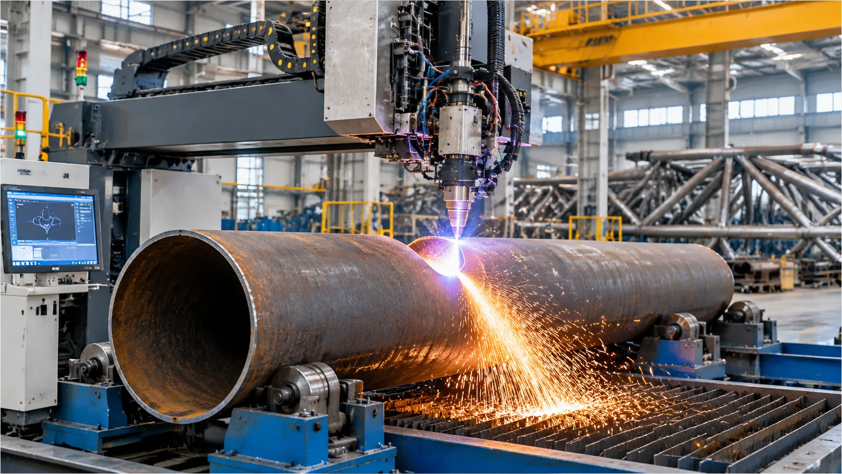
Industrial steel fabrication enforces automated manufacturing tolerances unachievable in the field. Multi-axis CNC plasma pipe profiling cuts complex saddle-shaped tubular intersections to within ±0.5 mm, guaranteeing complete-joint-penetration (CJP) weld geometry in compliance with AWS D1.1 and EN 1090-2 Execution Class 3 (EXC3). Automated blast finishing cleans steel surfaces to ISO 8501-1 Sa 2.5, preparing the substrate for factory-applied, high-build epoxy zinc-rich primer systems (80 μm minimum DFT).
2×2 / Multi-bolt anchor cluster positioned around orthogonal survey axes with template cage locking.
Baseplate erection face supported on leveling nut/shim packs above top of concrete pier prior to grouting.
These automated plant controls ensure that when structural modules arrive at the jobsite, anchor bolt interfaces set to ±3 mm survey limits pin directly into place. This eliminates costly on-site modifications, minimizes field welding, and achieves seismic behavior response factors (R) up to 6.0 for superior energy dissipation during severe dynamic ground motions.
Primary Structural Typologies for Large-Span Sports Arenas
When engineering a large span prefabricated steel structure sports stadium, structural weight, boundary constraints, and erection sequencing determine roof typology selection. Arena enclosures operate under severe self-weight penalties as spans widen, requiring load paths that optimize material placement between pure compression and direct tension. Modern sports infrastructure relies on three proven prefabricated configurations.
1. Three-Dimensional Tubular Space Trusses
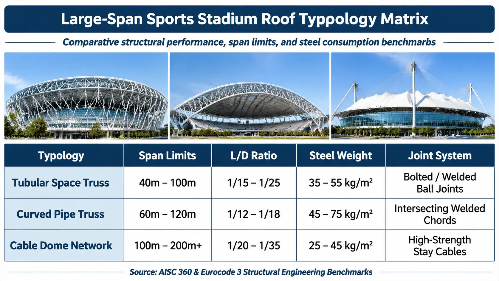
Space grid frameworks utilizing circular hollow sections (CHS) configured in orthogonal or diagonal pyramids deliver two-way load distribution, making them ideal for ground plans with square or low-aspect-ratio rectangular footprints. Tubular space trusses achieve 35 to 55 kg/m² steel consumption across 40m to 100m spans. They provide the standard superstructure for municipal basketball arenas and natatoriums.
Node connectivity relies on bolt-sphere joints (for rapid, fastener-only site assembly) or welded hollow spherical joints (for higher bending stiffness and dynamic fatigue resistance). Workshop fabrication requires multi-axis CNC intersecting wire cutting on automated beds to maintain branch pipe profiling tolerances within ±0.5 mm. Spheres are drop-forged from AISI 1045 or Q355B normalized round bar, with internal threads inspected under EN 1090-2 Execution Class 3 (EXC3) rules. Because boundary conditions provide continuous multi-point ring beam support, these grids accommodate large interior MEP distribution systems while limiting total deflection to L/400 under dead plus live service loads.
2. Inverted Triangular Curved Pipe Trusses
For asymmetric stadium envelopes, open-air grandstands, and football pitch canopies, inverted triangular pipe trusses (one bottom tension/compression chord paired with two top chords stabilized via continuous web lacings) provide high out-of-plane torsional rigidity. Curved pipe trusses maintain span-to-depth ratios of 1/12 to 1/18 for grandstand cantilevers up to 120m, yielding dead load steel consumption figures between 45 and 75 kg/m².
The open chord layout permits deep integration of high-output broadcast floodlighting rigs, public address lines, and maintenance catwalks directly within the structural envelope without increasing wind profile drag. Fabrication eliminates heavy gusset plates by relying on direct pipe-to-pipe profile welds designed under AWS D1.1 Section 9 guidelines for tubular joints. Prefabricated truss segments measuring 18m to 30m receive automated Sa 2.5 blast cleaning and a minimum 80 μm dry film thickness (DFT) epoxy zinc-rich primer prior to site delivery, minimizing field welding to splice joints positioned at points of minimum bending moment.
3. Prestressed Cable-Truss and Cable-Dome Hybrid Networks
When clear spans exceed 100m, rigid solid-web or all-steel truss designs experience self-weight deflection limits that render standard framing uneconomical. Tension hybrid architectures decouple primary load paths: rigid structural steel elements (outer perimeter compression rings fabricated from Q390D or Q420D box girders) resist inward buckling, while high-tensile flexible tendons manage vertical downward and net wind uplift forces.
Prestressed cable-dome networks use ultra-high-strength steel stay cables (1670-1860 MPa), reducing structural weight by up to 28% compared to traditional spatial truss solutions. At the Chengdu Phoenix Mountain Sports Park, the 200m clear-span hybrid cable-stayed dome uses inner tension rings and radial cast-steel cable clamps to maintain structural stiffness under seismic and lateral wind loads. Cable strands coated with zinc-5% aluminum mischmetal alloy provide over 50 years of corrosion resistance in humid arena environments. Erection requires synchronous hydraulic strand jacking calibrated to within 2.5% of design pretension per EN 1993-1-11 tolerances.
| Structural Typology | Clear Span Range (m) | Span-to-Depth (L/D) Ratio | Dead Load Steel Tonnage (kg/m²) | Primary Joint Mechanism | Erection Methodology |
|---|---|---|---|---|---|
| Tubular Space Truss | 40 to 100 | 1/15 to 1/25 | 35 to 55 | Bolt-sphere or welded hollow ball joints | Full-floor assembly with hydraulic strand-jack synchronized lifting |
| Inverted Curved Pipe Truss | 60 to 120 | 1/12 to 1/18 | 45 to 75 | Direct intersecting pipe profile welds (AWS D1.1) | Segmented tandem-crane lift on temporary shoring towers |
| Prestressed Cable Hybrid Network | 100 to 220+ | 1/20 to 1/35 | 28 to 48 (Steel) + 6 to 12 (Cable) | Pin-connected cast steel cable nodes (ASTM A148) | Perimeter ring assembly followed by tensioned cable pull-up |
International Structural Design Codes & Engineering Standards
Executing an export-grade large span prefabricated steel structure sports stadium requires code harmonization between AISC 360-16 and Eurocode 3 (EN 1993), alongside GB 50017-2017. International turnkey procurement demands dual-track structural compliance across North American and European regulatory environments, with adaptations for Chinese domestic projects. Turnkey engineering parity requires reconciling material ductility and member slenderness across AISC 360-16 (LRFD with seismic provisions per AISC 341-16) and Eurocode 3 (EN 1993-1-1, EN 1993-1-8, and EN 1993-1-11 for tension components). Load combination factors must also satisfy Chinese standards GB 50017-2017 and GB 50011-2010.
Material equivalency bridges ASTM A992 or A572 Grade 50 (nominal yield strength Fy = 345 MPa), European S355JR/J2 per EN 10025-2, and Chinese Q355B/Q355D per GB/T 1591. For long-span cantilevers and tension-truss pin connections, impact toughness demands Charpy V-notch energy minimums of 27 J at -20°C. Fabrication adheres to EN 1090-2 Execution Class 3 (EXC3) or EXC4 and AWS D1.1, utilizing CNC plasma and laser cutting tolerances held within ±0.5 mm, automated submerged arc welding (SAW), and base plate anchor bolt layouts controlled to ±3 mm.
Serviceability limit states govern the structural depth of stadium roofs. Serviceability roof deflection limits calibrated between L/300 (live load) and L/500 (total load) are enforced across spatial space trusses, box-girder arches, and tied cantilevers. These boundaries eliminate water ponding hazards, mitigate secondary bending stresses at rigid joint nodes, and prevent joint fatigue under thermal cycles spanning ΔT of ±35°C.
Large overhanging canopies are prone to aeroelastic flutter and severe wind uplift. Aerodynamic boundary-layer wind tunnel testing is required for complex cantilevers with uplift suction coefficients Cp exceeding -1.8, where localized separation bubbles at leading canopy edges create extreme net negative pressures. Scale testing (typically 1:200 to 1:300) establishes multi-directional force coefficients, peak net pressure distributions, and vortex shedding frequencies, sizing hold-down purlin brackets and cable pre-tension anchors against aeroelastic divergence.
Grandstand tier systems must satisfy human-induced dynamic serviceability. Natural frequency limit states set above 3.0 Hz for grandstand structures eliminate rhythmic crowd resonance per ISO 10137 and AISC Design Guide 11. Coordinated spectator jumping and stomping creates forcing harmonics between 1.5 Hz and 2.8 Hz. Maintaining fundamental vertical modes above 3.4 Hz and fundamental lateral modes above 1.5 Hz avoids dynamic amplification, biomechanical discomfort, and structural fatigue.
| Design Parameter | AISC / ASCE (United States) | Eurocode (European Union) | GB Standard (China) | Harmonized Turnkey Threshold |
|---|---|---|---|---|
| Structural Steel Specification | AISC 360-16 (LRFD) / AISC 341-16 | EN 1993-1-1 / EN 1993-1-8 / EN 1993-1-11 | GB 50017-2017 / GB 50011-2010 | Full yield, stability, and ductility parity |
| Structural Material Grade | ASTM A992 / A572 Gr 50 (Fy = 345 MPa) | EN 10025-2 S355JR / J2 (Fy = 355 MPa) | GB/T 1591 Q355B / Q355D (Fy = 355 MPa) | CVN toughness ≥ 27 J at -20°C |
| Roof Truss Deflection Limit | L/360 (Live) to L/240 (Total) (IBC / AISC) | L/300 (Variable) to L/500 (Total) (EN 1990) | L/400 (Live) to L/500 (Total) (GB 50017) | L/300 (Live load) / L/500 (Total load) |
| Canopy Aerodynamic Uplift | ASCE 7-16 Chapter 31 Wind Tunnel Procedure | EN 1991-1-4 Wind Tunnel / Boundary Layer | GB 50009-2012 Wind Tunnel Protocol | BLWT mandatory when local Cp exceeds -1.8 |
| Grandstand Dynamic Resonance | AISC Design Guide 11 (fv > 3.0 Hz) | ISO 10137 / UK IStructE (fv > 3.4 Hz) | JGJ/T 271-2012 (fv > 3.0 Hz) | fv > 3.0 Hz vertical, fl > 1.5 Hz lateral |
| Fabrication and Erection Tolerance | AISC 303-16 / AWS D1.1 | EN 1090-2 Class EXC3 / EXC4 | GB 50205-2020 / GB 50661-2011 | CNC cut ±0.5 mm, anchor bolts ±3 mm |
Material Specifications, Node Mechanics & Joint Engineering
Engineering a large span prefabricated steel structure sports stadium demands strict metallurgical qualification and node mechanics to resist static gravity, dynamic seismic cycles, and violent aerodynamic wind uplift. Because arena roofs span between 60 and 180 meters without internal support columns, primary chords and node junctions experience immense multi-axial stress states. Selecting steel chemistry, fracture toughness criteria, and connection geometries dictates long-term structural survivability.
Primary Chord Metallurgy and Through-Thickness Integrity
Primary steel chords specified in Q355ND / ASTM A572 Gr 50 / S355JR with Charpy V-notch impact toughness at -20°C (min 27 J) are the baseline specification for standard-demand tubular trusses and perimeter space frames per GB/T 1591 and EN 10025-2. For long-span tension chords, cantilever truss hubs, and heavy thrust arches where member cross-sections must be constrained, design protocols transition to high-strength, low-alloy grades Q420B and Q460D (yield strength 420 to 460 MPa). Structural pipe conforms to GB/T 8162 or cold-formed hollow structural sections per ASTM A500 Grade B/C.
Heavy welded connections generate triaxial tensile strain fields during weld cooling. When thick chord plates exceed 40 mm, shrinkage strains induce severe separation along internal non-metallic inclusions. Through-thickness lamellar tearing mitigation achieved through Z-direction quality grades Z25 and Z35 per EN 10164 and GB/T 5313 guarantees minimum reduction of area values of 25% and 35% during perpendicular tensile testing. This prevents subsurface cleavage beneath full-penetration groove welds.
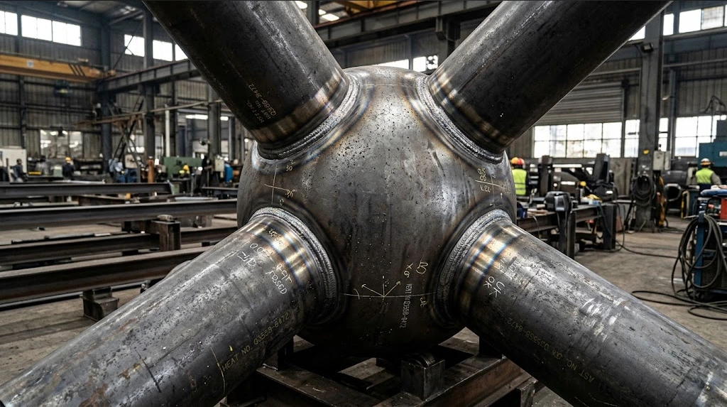
Node Mechanics: WSHJ, BSJ, and Cast Steel Geometries
Three node configurations dominate sports arena framing, each handling specific joint stiffness and force concentrations:
- Welded Spherical Hollow Joints (WSHJ): Fabricated from two hot-pressed hemispheres hot-forged per JG/T 11, welded with a submerged arc complete-joint-penetration (CJP) seam, and profiled to receive converging hollow structural sections (HSS). Internal stiffening ribs are welded inside when wall punching shear exceeds allowable limit states.
- Bolted Spherical Nodes (BSJ): Utilized in space frame assemblies where secondary infill trusses require rapid field erection without site welding. High-strength bolt assemblies conform to ASTM F3125 Grade A325/A490 or EN 14399 Grade 10.9 HSFG preloaded bolts, screwed internally into forged 45# steel spheres through sleeve couplers.
- Cast Steel Nodes (GS-20Mn5 / G20Mn5): High-stress critical nodes require Q420B/Q460D or cast steel nodes (G20Mn5 per EN 10293) to eliminate intersecting weld congestion. When five or more large-diameter tubular chords intersect at skewed geometric angles, standard branch profiling produces impossible welding root clearances and high residual stress fields. Cast steel nodes provide continuous, smooth transition fillets, routing force lines without geometric notches.
FEA Modeling, Fatigue Life, and Workshop Tolerances
Finite Element Analysis (FEA) solid modeling protocols evaluate stress concentration factors (SCF) under high-cycle aerodynamic buffeting. Nodes are meshed with second-order 3D solid elements (such as C3D8R) in ANSYS or ABAQUS. Linear elastic analysis confirms peak localized Von Mises stress remains within 1.3 times nominal yield stress, while sub-modeling checks high-cycle fatigue cracking per Eurocode 3 (EN 1993-1-9) detail categories.
Shop fabrication applies precise numerical limits: multi-axis intersection pipe ends are profiled by 5-axis CNC plasma cutters to a tolerance of ±0.5 mm. Bevel angles adhere to AWS D1.1 structural welding requirements. All CJP welds on critical load nodes receive 100% non-destructive evaluation (NDE) through ultrasonic testing (UT) per ISO 17640 Level B and magnetic particle testing (MT) per ISO 17638.
| Structural Component | Material Grade & Reference Standard | Min Yield Strength (MPa) | Tensile Strength (MPa) | Impact Energy (Charpy V-Notch) | Typical Arena Application |
|---|---|---|---|---|---|
| Standard Lattice Chords | Q355ND / ASTM A572 Gr 50 / S355JR | 355 | 470 - 630 | 27 J at -20°C | Intermediate truss webs, roof purlins, secondary bracings |
| Heavy Tension Chords | Q420B / Q460D / ASTM A656 Gr 60 | 420 - 460 | 520 - 680 | 34 J at -20°C | Main-span bottom chords, tie arches, suspension cable rings |
| Restrained Node Plates | Q355ND-Z25 / Q355ND-Z35 (EN 10164) | 355 | 470 - 630 | 27 J at -20°C | Cruciform gussets, heavy baseplates subjected to through-thickness pull |
| Cast Structural Hubs | G20Mn5 / GS-20Mn5 (EN 10293 / DIN 17182) | 300 | 500 - 650 | 27 J at -20°C | Multi-branch column capitals, roof thrust bearing assemblies |
| Bolted Spherical Nodes | 45# Forged Steel (GB/T 699) / C45E (EN 10083) | 355 | 600 - 750 | 25 J at 0°C | Pre-engineered double-layer space grids, canopy infill frames |
| High-Tension Fasteners | ASTM F3125 A490 / EN 14399-4 Gr 10.9 | 900 | 1040 - 1200 | 30 J at -20°C | Moment node splices, base shoe slip-critical friction connections |
Where we can help
Large-span sports venues and industrial facilities require meticulous connection detailing and automated dimensional control to eliminate field reaming. Operating from our 60,000 sqm fabrication facility, Jinan XinQiao Steel Structure Co., Ltd. deploys multi-axis CNC drilling and plasma cutting lines to maintain sub-millimeter bolt-hole and pipe-saddle tolerances across spatial trusses, heavy portal frames, and box girders. We fabricate complete structural assemblies under AISC 360 and AWS D1.1 quality standards to accelerate field erection sequences. Review our certified production parameters and public arena & stadium structural specifications to integrate standard connection schedules directly into your framing models.
Atmospheric Corrosivity Protection & Surface Coating Systems
Structural longevity in a large span prefabricated steel structure sports stadium depends entirely on matching the protective coating regime to micro-climate operating conditions. Enclosed arenas, open-air perimeter trusses, and aquatic complexes present radically different corrosion exposure profiles. Fabricating structural assemblies at our workshop requires strict execution of surface preparation standards, precise dry film thickness (DFT) tracking, and verified chemical compatibility between protective barrier layers and passive fireproofing coatings.
Environmental Corrosivity Zonation (ISO 12944)
Sports venue envelopes rarely fall into a single atmospheric category. Engineering design must divide the venue into distinct exposure zones per ISO 12944-2:
- Category C3 (Medium Corrosivity): Standard indoor dry basketball arenas and concourses with conditioned air and low relative humidity (RH < 60%). Atmospheric contamination is low to moderate.
- Category C4 (High Corrosivity): Exterior perimeter steelwork, open canopies in urban coastal sports parks, and structures exposed to moderate airborne salinity, industrial sulfur dioxide, or high seasonal condensation.
- Category C5 / C5-M (Very High / Severe Marine): Oceanfront stadium canopies, exposed structural cantilever trusses within coastal splash-mist ranges, and high-salinity marine winds.
- Category CX (Extreme Industrial / Chemical): High-humidity chlorinated natatorium environments. Evaporating pool water releases aggressive chloramine vapors (trichloramine, NCl3) that concentrate on cool steel surfaces above 70% RH, driving rapid localized pitting and stress corrosion cracking (SCC) on unsealed joints.
Surface Preparation and Blast Profiles
Coating adhesion is governed by mechanical interlocking. Surface preparation specified to Sa 2.5 per ISO 8501-1 with 40-75 μm blast profile roughness is enforced for all structural members prior to primer deposition. Automated wheel blast units use a calibrated 60/40 blend of steel grit (GL25/G40) and steel shot (S330) to achieve an angular profile corresponding to ISO 8503-1 Medium (G).
Prior to abrasive blasting, sharp thermal-cut edges must be ground to a minimum radius of 2.0 mm per EN 1090-2 to prevent premature edge-retraction thinning of the liquid coating. Soluble salt testing is performed per ISO 8502-6/9 (Bresle method), limiting total surface chloride contamination to less than 20 mg/m² for C5-M and natatorium steelwork before application.
Protective Regimes: TSA, HDG, and High-Build Polymer Coatings
For severe exposures, single-barrier systems cannot meet multi-decade design lives without prohibitive field recoating cycles. Jinan XinQiao deploys metalized duplex and high-build fluoropolymer barrier regimes:
- Thermal Spray Aluminum (TSA) vs. Hot-Dip Galvanizing (HDG): Hot-dip galvanization per ISO 1461 minimum 85 μm local coating thickness for secondary purlins and bolted hardware delivers sacrificial galvanic protection. However, massive three-dimensional space trusses and long-span box girders exceed standard galvanizing kettle dimensions (typically 15.5 m × 2.4 m × 3.0 m) and risk high-temperature thermal distortion. For these primary members, automated Thermal Spray Aluminum (TSA, 99.5% Al per ISO 2063) or Thermal Spray Zinc (TSZ, 85/15 Zn-Al) applied at 80 to 100 μm provides a dense, flexible sacrificial layer with zero thermal deformation risk.
- Epoxy MIO Intermediate Barriers: High-build Epoxy Micaceous Iron Oxide (MIO) coats provide a physical barrier. The overlapping plate-like structure of specular hematite platelets forces moisture and chloride ions along an extended diffusion path, reducing permeation rates.
- High-Performance Topcoats: For ultimate chemical and UV resistance, two-pack fluorocarbon (PVDF) topcoats or aliphatic polysiloxanes replace standard polyurethanes. The carbon-fluorine bond in PVDF exhibits extreme bond dissociation energy (485 kJ/mol), resisting solar UV breakdown and acid rain erosion. For the C5-M marine regime: Thermal Spray Aluminum (80 μm) + Epoxy MIO (100 μm) + Fluorocarbon topcoat (60 μm) providing >25 years to first maintenance delivers field-verified durability under aggressive maritime exposure.
Integration with Passive Fire Protection (PFP)
Sports stadium occupancy classifications mandate fire resistance ratings for primary structural members. Intumescent coating systems tested to EN 13381-8 / UL 263 delivering 60, 90, and 120-minute structural fire resistance ratings must seamlessly integrate into the corrosion protection build-up.
Thin-film solvent-borne or waterborne acrylic intumescents are specified for dry interior zones (C1 to C3), expanding up to 50 times their original DFT under heat exposure to form an insulating carbonaceous char. For high-humidity, natatorium, or semi-exposed canopy zones (C4, C5, CX), epoxy-based intumescents are mandatory. Solvent-borne acrylics exposed to moisture-cycling undergo plasticizer leaching and binder degradation, compromising thermal activation.
System compatibility requires strict adherence to tested build-ups:
- Primer: Two-component zinc phosphate or epoxy blast primer (DFT 50 to 75 μm). Zinc-rich primers exceeding 80% zinc dust by weight are prohibited beneath waterborne intumescents due to potential zinc salt formation (white rust) causing delamination.
- Intumescent Core: Hydrocarbon or cellulosic fireproofing engineered to member section factors (Am/V or Hp/A), with dry film thicknesses ranging from 800 μm (60-minute rating) to 3,500 μm (120-minute rating).
- Sealer Topcoat: Fully compatible aliphatic polyurethane, polysiloxane, or chlorinated rubber topcoat applied at 50 to 75 μm to lock out moisture and atmospheric carbon dioxide, preventing intumescent core degradation.
Table 4 details the standardized coating configurations across stadium environmental zones.
Table 4: Structural Steel Coating Systems and Fireproofing Matrices
| Corrosivity Category (ISO 12944) | Structural Zone / Member Type | Surface Prep (ISO 8501-1) & Profile | Primer & Intermediate Coats (DFT) | Topcoat / Fireproofing Regimes (DFT) | Total System DFT (μm) | Design Life to First Major Maintenance |
|---|---|---|---|---|---|---|
| C3 (Indoor Arena) | Primary Roof Trusses & Intermediate Girders | Sa 2.5 (40-60 μm) | Epoxy Zinc Phosphate Primer (75 μm) + Epoxy MIO Intermediate (100 μm) | Solvent-borne Intumescent (EN 13381-8, 60-min: 950 μm) + Polyurethane Topcoat (50 μm) | 1,175 | 15-25 Years |
| C3 (Indoor Arena) | Cold-Formed Secondary Purlins & Sag Rods | Chemical Pickling | Hot-Dip Galvanizing per ISO 1461 | Self-passivating zinc patina / Optional direct-to-metal acrylic (50 μm) | 85 (minimum) | >25 Years |
| C4 (Urban Coastal) | Exposed Perimeter Columns & Wind Bracing | Sa 2.5 (50-75 μm) | Zinc-Rich Epoxy Primer (70 μm) + High-Build Epoxy MIO (150 μm) | Aliphatic Acrylic Polyurethane (60 μm) / Optional 90-min Epoxy PFP (1,800 μm) | 280 (without PFP) / 2,080 (with PFP) | >25 Years |
| C5-M (Severe Marine) | Exterior Roof Cantilever & Space Truss Canopies | Sa 2.5 (50-75 μm, Rz) | Thermal Spray Aluminum (TSA, 80 μm) + Low-Viscosity Epoxy Sealer/MIO (100 μm) | Fluorocarbon (PVDF) Topcoat (60 μm) | 240 | >25 Years |
| CX (Natatorium / High Chloramine) | Enclosed Swimming Complex Roof Superstructure | Sa 2.5 (50-75 μm, Chlorides <20 mg/m²) | Two-Pack Epoxy Polyamide Barrier Primer (80 μm) + High-Solid Epoxy MIO (160 μm) | 100% Solids Epoxy Intumescent (120-min: 2,600 μm) + High-Build Polysiloxane Topcoat (80 μm) | 2,920 | >25 Years |
| Secondary Fasteners | A325 / A490 / Grade 10.9 Structural Bolts | Degreased & Micro-blasted | Hot-Dip Galvanized per ASTM A153 / ISO 10684 (min 55 μm) | Fluoropolymer / PTFE Dispersion Coating over base galvanizing (25 μm) | 80-100 | >25 Years |
Quality Control and Application Envelopes
Surface coating application requires strict adherence to ambient environmental limits:
- Steel surface temperature must remain at least 3°C above the calculated dew point.
- Relative humidity must remain below 85% for standard epoxies and polyurethanes (below 65% for waterborne intumescents).
- Workshop ambient temperature must range between 10°C and 38°C.
Film thickness measurements follow SSPC-PA 2 protocols, employing calibrated magnetic gauges on non-ferrous and ferrous bases. Intercoat pull-off adhesion testing is conducted according to ISO 4624 / ASTM D4541 on sacrificial witness plates fabricated alongside the main structural members. Acceptable cohesive failure within the coating layers must exceed 5.0 MPa for polymer systems and 8.0 MPa for TSA duplex systems, confirming substrate wetting and mechanical bond performance.
Prefabricated Structural Steel vs. Cast-in-Place Concrete: Comparative Analysis
When engineering a large span prefabricated steel structure sports stadium, structural system selection governs direct framing procurement, geotechnical foundation sizing, global crane logistics, and multi-year construction scheduling. Sports complexes are frequently sited on alluvial flatlands, river estuaries, or reclaimed waterfront parcels characterized by low bearing capacity and high groundwater tables. In these geotechnical conditions, structural dead load becomes the dominant driver of substructure capital expenditure.
Dead Load, Foundation Sizing, and Seismic Mass
Cast-in-place reinforced concrete (unit weight approximately 24 kN/m³) and post-tensioned beam systems impose massive sustained gravity dead loads on the subgrade. Steel structures reduce superstructural dead weight by up to 60%, decreasing foundation pile volume and foundation capex by 20% to 35%.
Under ASCE 7-22 and Eurocode 8 seismic provisions, equivalent lateral base shear (V = CsW) scales directly with effective seismic weight (W). Prefabricated long-span space trusses and box girders fabricated from high-strength ASTM A992 or Q355B steel dramatically reduce seismic base shear compared to monolithic concrete slabs and cast frames. Reduced seismic demand directly diminishes the diameter and embedment depth of driven prestressed concrete cylinder piles or bored cast-in-situ friction piles. This reduction also lowers reinforcing steel density, avoiding extensive ground improvement methods like deep soil mixing or jet grouting.
Schedule Optimization: Parallel Fabrication vs. Serial Curing
The delivery schedule diverges across both typologies:
- Serial Cast-in-Place Concrete: Requires on-site formwork erection, complex shoring towers extending from the bowl slab, high-density rebar placement, multi-stage concrete pours, and strict 28-day curing intervals before formwork stripping and post-tensioning tendon grouting per ACI 318-19. Superstructure construction cannot begin until substructure works reach certified compressive design strengths.
- Parallel Prefabricated Steel: Substructure civil works and superstructure roof fabrication run simultaneously on parallel paths. While foundation excavation and pile caps progress on site, primary structural trusses undergo automated CNC plasma cutting (maintaining standard tolerances within ±0.5 mm), multi-pass submerged arc welding under AWS D1.1 quality control, automated Sa 2.5 centrifugal grit blasting, and high-performance paint application (epoxy zinc-rich primer applied to 80 μm DFT) in a climate-controlled plant.
Schedule compression of 30% to 45% achieved via concurrent foundation civil works and automated off-site steel fabrication allows rapid modular erection once the anchor bolt layouts (held within ±3 mm field tolerance) are cast and verified.
Sightlines, Footprints, and Circular Lifecycle Metrics
Spectator sightline C-values optimized by eliminating bulky concrete transfer beams and maximizing column-free clear areas generate direct commercial returns for venue operators. Long-span steel tube trusses and cable-stayed envelopes span 80 meters to over 200 meters without intermediate columns, preventing the visual obstruction common with deep concrete girders that often exceed 2.5 meters in web depth. Furthermore, structural steel column profiles occupy less than one-third of the cross-sectional floor plate area of comparable axial-capacity reinforced concrete piers, maximizing concourse circulation.
From a sustainability standpoint, structural steel possesses a 100% recycling rate with cradle-to-gate embodied carbon reductions exceeding 30% when using EAF (Electric Arc Furnace) steel compared to conventional blast furnace-basic oxygen furnace routes or primary Portland cement binders. At the eventual decommissioning phase, bolted steel assemblies (governed by AISC 360-16 and EN 1090-2 Execution Class EXC3 or EXC4) allow systematic deconstruction and structural steel element reuse, avoiding the downcycling to aggregate fill that characterizes demolished reinforced concrete.
Table 5: Head-to-Head Engineering and Financial Benchmarks
| Structural Parameter | Prefabricated Structural Steel Envelope | Cast-in-Place / Post-Tensioned Concrete |
|---|---|---|
| Superstructure Dead Load | 0.80 to 1.60 kN/m² (roof footprint) | 3.50 to 7.00 kN/m² (roof and transfer girders) |
| Foundation Capex Impact | Baseline (20% to 35% lower pile volume) | +25% to +45% pile cap depth and pile quantities |
| Clear Span Feasibility | 60 m to 250+ m via trusses, arches, domes | Limited; exceeding 45 m requires heavy post-tensioning |
| Substructure-Superstructure Workflow | Concurrent (off-site steel fabrication during civil works) | Sequential (dependent on concrete pour and 28-day cure) |
| Site Erection Speed | 250 to 500 m² structural roof cover per week | 80 to 150 m² per week including shoring and strip times |
| Sightline C-Value Impact | C-90 to C-120 achievable without column intrusion | Bulky drop beams frequently degrade upper-tier C-values |
| Deflection Control (Serviceability) | Precise cambering during fabrication (AISC DG 3) | Subject to long-term concrete creep and shrinkage |
| Environmental Embodied Carbon | Low with scrap-fed EAF steel (<0.45 t CO2e/t steel) | High (cement clinker calcination: 0.85 t CO2e/t cement) |
| End-of-Life Circularity | 100% recyclable or direct structural member reuse | Downcycled aggregate; extensive landfill burden |
Advanced Factory Fabrication, QA/QC & Shop Pre-Assembly Protocols
Erection of a large span prefabricated steel structure sports stadium permits zero tolerance for field rectification. When crane hooks carry 80-metric-ton cantilever truss segments 50 meters above ground level, every connection interface must seat immediately without thermal gouging or mechanical reaming. Achieving this installation precision requires strict factory manufacturing protocols governed by EN 1090-2 Execution Class 3 (EXC3) and AISC 303-16 guidelines.
Fabrication begins with automated pipe profiling. We deploy 5-axis and 6-axis CNC intersecting line pipe profile cutting guaranteeing angular bevel accuracy within ±0.5° and length tolerance within ±1.0 mm. These units execute multi-planar, variable-angle saddle cuts on tubular chords and web diagonals up to 1,200 mm in diameter. The automated torch trajectory calculates dynamic bevel angles along the 3D intersecting curve, creating variable root openings and transitions required for complete joint penetration (CJP) welding without backing bars.
Automated welding procedures use submerged arc welding (SAW) for built-up box girders and robotic flux-cored arc welding (FCAW, process 136) for complex spatial nodes. All Welding Procedure Specifications (WPS) and Procedure Qualification Records (PQR) are qualified under AWS D1.1/D1.1M Clause 4 and ISO 15614-1. Preheating and interpass temperatures are strictly enforced via multi-channel digital induction coils according to AWS D1.1 Table 5.8, using low-hydrogen consumables (diffusible hydrogen content below 4 ml/100g of deposited weld metal) to prevent cold cracking in thick-plate ASTM A992 materials. The same temperature controls protect thick-plate Q355B and Q420B grades against cracking.
| Component / Joint Type | Fabrication Standard | Primary NDT Method | Acceptance Criteria | Dimensional Tolerance |
|---|---|---|---|---|
| Tubular Node CJP Welds | AWS D1.1 / ISO 15614-1 | 100% UT + 20% MPI | AWS D1.1 Class A / ISO 5817 Level B | Bevel angle ±0.5°, gap ±1.0 mm |
| Built-up Chord Flange CJP | EN 1090-2 (EXC3) | 100% UT per EN ISO 17640 | EN ISO 11666 Acceptance Level 2 | Plate misalignment ≤ 1.5 mm |
| Web Stiffener Fillet Welds | AWS D1.1 Clause 8 | 100% Visual + 20% MPI | AWS D1.1 Table 8.1 (Cyclic) | Leg size -0 mm / +2.0 mm |
| Cast Steel Spherical Nodes | ASTM A148 / EN 10293 | 100% RT or PAUT | ASTM E446 Level II / ISO 4993 | Node center offset ≤ 1.5 mm |
| Truss Pinned End Bearings | AISC 303-16 Section 7 | Dimensional Laser Verification | AISC Code of Standard Practice | Pin hole center-to-center ±1.0 mm |
Our Non-Destructive Testing (NDT) regime follows a multi-tier structure. We mandate 100% Ultrasonic Testing (UT) and 20% Magnetic Particle Inspection (MPI) for all CJP welds per AWS D1.1 Class A / EN ISO 5817 Level B. Ultrasonic examinations comply with EN ISO 17640 techniques, targeting internal volumetric defects, lack of fusion, and root porosity. Magnetic Particle Inspection per ASTM E709 and EN ISO 17638 covers all high-stress node-to-chord fillets to detect micro-fissures in heat-affected zones. Radiographic Testing (RT) per EN ISO 17636 or Phased Array Ultrasonic Testing (PAUT) is applied to all cast steel and forged spherical joint nodes subjected to complex multi-axial tension.
Prior to surface blasting and protective coating application, dimensional verification occurs via both digital and physical methods. We perform digital 3D terrestrial laser scanning (LIDAR) paired with TEKLA Structures LOD 400 models to verify dimensional tolerances within ±2 mm across overall spatial assemblies. The captured point cloud undergoes point-to-surface deviation analysis against the structural model, identifying any camber discrepancies, bolt-hole circle misalignments, or node skewing.
In addition, shop 1:1 trial assembly protocols are required for first-of-kind cantilever trusses and spherical node clusters prior to international shipment. Fabricated modules are locked on leveled, ground-anchored jigs in their true spatial orientation. Field splices, temporary pinned connections, and pre-stressed cable anchoring lugs are mechanically coupled to prove site fit-up, confirming that zero secondary stresses are introduced during final stadium erection.
Global Logistics, Containerization & Transport Optimization
Shipping complex geometry for a large span prefabricated steel structure sports stadium demands strict integration between connection design, modular fabrication, and intermodal transport limitations. Unplanned breakbulk cargo incurs steep ocean freight surcharges, port congestion delays, and heightened risk of transit deformation. To mitigate these liabilities, our engineering team executes modular spool segmentation and virtual container-stuffing simulations directly inside Tekla Structures before issuing fabrication drawings to the shop floor.
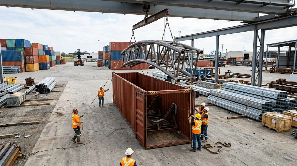
Modular truss segmentation is engineered to standard 11.8 m transport lengths to optimize 40ft High Cube and Open Top container stuffing rates (>85% volumetric efficiency). Standard ISO 40ft High Cube (40HC) containers feature an internal length of 12.03 m, a width of 2.35 m, and a door opening height of 2.58 m. By restricting primary truss chord segments to a maximum cut length of 11.80 m and sub-trusses to an absolute transport width of 2.30 m, we leave 230 mm of longitudinal and 50 mm of lateral clearance for perimeter dunnage, lifting slings, and end-wall buffer timber. When assemblies feature three-dimensional bracing outriggers or cross-sectional depths between 2.35 m and 2.65 m, components are routed to 40ft Open Top (40OT) containers for overhead crane loading. Curved elements exceeding container profiles are transported on 40ft Flat Racks or dedicated breakbulk stowed below deck, utilizing tailored spatial cradles to prevent out-of-plane buckling under dynamic sea-swell accelerations.
| Freight Mode | Usable Internal Envelope (L × W × H) | Max Payload (Metric Tons) | Typical Stadium Structural Component | Target Stuffing Efficiency (%) | Handling and Lashing Protocol |
|---|---|---|---|---|---|
| 40ft High Cube (40HC) | 12.03 m × 2.35 m × 2.69 m | 28.50 | Segmented chord spools, secondary purlins, bracing rods | 85 - 92 | Timber dunnage, ratchet lashings at 2.0 m centers |
| 40ft Open Top (40OT) | 12.02 m × 2.35 m × 2.38 m | 28.20 | Deep perimeter box girders, pre-assembled truss modules | 80 - 87 | Top-loaded via spreader bar, tarpaulin weather seal |
| 40ft Flat Rack (FR) | 11.65 m × 2.20 m × 2.25 m (flush) | 40.00 | Oversized tree-column nodes, raker cantilever frames | 65 - 75 | Heavy-duty turnbuckles, welded base-plate stop chocks |
| Breakbulk (Charter) | Hold dependent (stowed below deck) | Subject to crane lift | Arch apex knuckles, continuous rolled CHS spatial arches | Variable (tonnage-based) | Custom sea-fastening frames, NDT post-voyage check |
Seaworthy export packaging requires ISO-compliant steel transport cradles and multi-layer VCI barrier films to prevent salt-fog contamination during transit. Long-haul ocean voyages expose structural steel to aggressive ISO 12944-2 C5-M marine atmospheric environments. Unprotected faying surfaces, bolt-hole penetrations, and pre-machined pin ears degrade rapidly under continuous humidity and salt spray. All structural assemblies finished with multi-coat epoxy systems (minimum dry film thickness of 120 to 160 μm over an Sa 2.5 blast profile) receive localized wrapping with multi-layer, heavy-gauge polyolefin Volatile Corrosion Inhibitor (VCI) films alongside moisture-absorbing desiccants. Custom-welded steel transport cradles, fabricated from Q235B structural rectangular tubing and lined with high-density polyethylene (HDPE) or vulcanized neoprene pads, anchor curved circular hollow section (CHS) pipe trusses. This eliminates metal-to-metal chafing, vibration-induced paint gouging, and transit ovalization. Heavy-duty woven polyester composite strapping, tensioned to certified ratings exceeding 50 kN, secures loads in compliance with the IMO/ILO/UNECE Code of Practice for Packing of Cargo Transport Units (CTU Code).
A piece-marking system directly mapped to the 3D TEKLA erection sequence with QR-coded component tags enables digital site intake. In sports facility projects requiring thousands of unique spatial truss nodes and purlin members, misidentified steel stalls field progress. Every member receives an embossed stainless steel nameplate and a secondary tear-resistant, UV-stable vinyl QR code tag riveted directly to the web or gusset interface. Scanning the code links field erectors directly to assembly coordinates, weight, center-of-gravity markers, and corresponding drawing revisions in the digital building information model. Complete shipping dossiers accompany each container release, containing EN 10204 Type 3.1 mill test certificates for base materials, EN 10204 Type 3.2 third-party inspection sign-offs for critical cast-steel nodes, complete non-destructive examination (NDE) logs (ultrasonic testing to AWS D1.1 Table 6.2 and ISO 17640), and detailed container packing lists mapped directly to the project erection phases.
On-Site Hoisting & Erection Sequencing Methodology
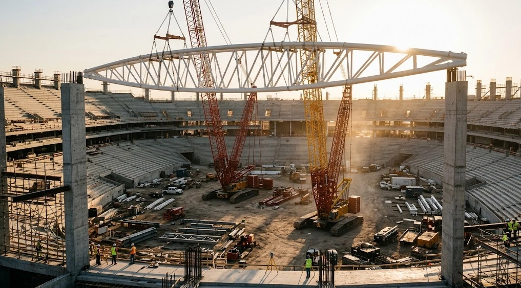
Erecting a large span prefabricated steel structure sports stadium demands total synthesis between temporary works engineering and dynamic stage-by-stage structural analysis. Before any steel leaves the staging yard, our engineering team executes 4D BIM construction sequencing in TEKLA Structures paired with staged finite element analysis (FEA). This digital twin models crane reach vectors, boom clear-to-structure clearances, outrigger ground-bearing pressures (GBP restricted to under 180 kPa through load-spreading steel mats), and real-time stress redistributions during intermediate non-closed structural states.
Every pick radius, rigging sling angle, and lifting lug weld (conforming to AWS D1.1 Table 6.1 visual and ultrasonic inspection criteria) is verified against crane capacity charts, keeping hoist loads below 75% for critical dual lifts.
| Hoisting Methodology | Structural Tonnage Range | Primary Lifting Plant | Temporary Works Footprint | Destressing Control Complexity |
|---|---|---|---|---|
| Integral Synchronous Strand-Jacking | 1,000 to 5,000+ t | Computer-controlled hydraulic pump stations, multi-strand jacks | Minimal at ground level; concentrated on permanent mega-columns | High (computer-monitored hydraulic release) |
| Tandem Crawler Crane Hoisting | 400 to 1,500 t (per sub-assembly) | Twin 650 t to 1,250 t lattice-boom crawlers | Moderate to high; requires heavy access pads and crane runways | Moderate (step-down shoring jacking) |
| Cantilever In-Air Assembly | 200 to 800 t (per cantilever truss) | 400 t crawler crane plus mobile assist cranes | Low ground footprint; requires perimeter tension stay-towers | High (incremental tie-back cable tension tuning) |
Primary Long-Span Erection Techniques
Our on-site engineering protocols apply three main erection methodologies based on site access, substructure load capacity, and roof geometry:
- Integral Hydraulic Strand-Jacking (Heavy Lifting): Computer-controlled synchronous hydraulic strand-jacking enables ground-level roof pre-assembly and lifting of structures exceeding 3,500 metric tons. The complete inner tension ring, radial trusses, and secondary purlin systems are built at grade level (elevation 0.00 m). Heavy strand jacks mounted to the tops of permanent concrete cores or composite mega-columns lift the assembly along high-tensile steel strand cables (ASTM A416, 1860 MPa). Digital stroke synchronization holds elevation variances within ±1.0 mm across all jack nodes, preventing parasitic torsional and bending stresses during the vertical ascent.
- Dual/Tandem Crawler Crane Hoisting: Utilized when internal bowl access allows heavy crawler positioning. Segmented primary space trusses (typically 40 m to 80 m long, weighing 120 t to 250 t) are hoisted simultaneously by dual lattice-boom cranes utilizing equalizer beams. Temporary modular shoring towers engineered with hydraulic unloading sand-boxes or jacks for controlled, stress-free destressing release support intermediate nodes until primary moment connections reach full capacity.
- Cantilever In-Air Assembly: Deployed for stadium canopies overhanging spectator bowls where shoring placement inside the bowl is prohibited. Truss segments advance sequentially outward from the perimeter buttresses. Temporary cable stays with pin-connected tie-backs hold each advancing cantilever bay, with coordinate geometry continuously verified using automated 3D laser tracking and electronic total stations against structural model baselines (±3 mm spatial tolerance).
Structural Destressing and System Release
Removing temporary shores transfers dead loads onto the completed permanent structural system. Destressing and unpropping sequences mathematically simulated via staged non-linear FEA to control redistribution of internal member forces prevent localized yielding or progressive buckling of critical compression chords. Multi-point unloading sand-boxes or synchronized hydraulic jacks lower the structure through incremental downward stages (typically 5 mm to 10 mm per step across concentric rings), ensuring secondary loads shed evenly into primary arch thrust lines or perimeter column anchor bolts.
High-Strength Bolting Quality Assurance
Splice connections across main trusses rely on slip-critical pre-tensioned bolting assemblies governed by the RCSC Specification for Structural Joints Using High-Strength Bolts and EN 1090-2 (Execution Class EXC3/EXC4).
Bolt tightening executed strictly to AISC/RCSC or EN 1090-2 standards with calibrated daily Skidmore-Wilhelm tension verification ensures every fastener group achieves designated clamping force. Field QA technicians confirm installation using tension control (TC) bolt assemblies (ASTM F1852 / F2280 or ISO 10.9 HVP) where the spline shears off only when minimum pre-tension is satisfied.
For standard hex assemblies, crews apply calibrated torque or the turn-of-nut method. Faying surfaces are blast-cleaned to Sa 2.5 (SSPC-SP 10) to secure a certified Class B slip coefficient (mean slip coefficient 0.50), free of paint, overspray, rust, or grease. All bolted assemblies undergo a 100% visual inspection, with torque-wrench verification applied to 10% of finished bolts across every joint node, logging results directly into the site inspection database.
Lifecycle Cost Economics, Capex Sizing & Budget Estimation
Capital expenditure analysis for a large span prefabricated steel structure sports stadium requires balancing direct structural fabrication and erection costs against long-term durability metrics. Budget allocations for these long-span canopies diverge significantly from conventional industrial portal frames due to specialized connection geometries, heavy multi-crane rigging operations, and stringent corrosion protection criteria.
On a typical turn-key stadium roof project, direct cost components divide into five primary capital streams:
- Raw structural steel procurement (ASTM A992, ASTM A572 Grade 50, or Q355B/Q420B heavy-wall seamless pipe): accounts for 35% to 45% of total structural costs.
- Specialized CNC cutting, automated beveling (±0.5 mm tolerance per EN 1090-2), and spherical node fabrication: 20% to 25%.
- High-performance anti-corrosion coating systems (ISO 12944 C4/C5 marine categories): 10% to 15%.
- Ocean freight containerization, breakbulk stowage, and regional customs logistics: 8% to 12%.
- On-site staging, multi-crane tandem mobilization, temporary shoring, and field erection: 15% to 20%.
Structural steel fabrication unit costs benchmarked at $1,800 to $2,800 per metric ton depending on node complexity and coating grade provide the baseline for initial project pro formas. When factoring in complete supply, engineering, freight, and site installation, finished long-span stadium roof system costs range between $140 and $320 per square meter of covered footprint area.
Table 6: Budgetary Pricing & Technical Allocation Across Span Classes
| Span Classification | Typical Roof Typology | Steel Consumption (kg/m²) | Fabrication Unit Cost ($/MT) | Installed System Cost ($/m²) | Primary Node Specification |
|---|---|---|---|---|---|
| 60m Indoor Sports Hall | Welded space frame or tubular planar trusses | 45 - 65 | $1,800 - $2,100 | $140 - $190 | Bolted spherical nodes (Grade 10.9 fasteners) |
| 100m Regional Arena Canopy | Perimeter ring-and-spoke cantilever truss system | 75 - 110 | $2,100 - $2,450 | $200 - $265 | Cast steel pinned nodes and branch-welded pipes |
| 150m+ National Stadium Bowl | Bidirectional cable-truss or suspended tension wheel | 120 - 175 | $2,450 - $2,800 | $270 - $320 | Forged spherical nodes with pre-stressed wire cables |
Beyond initial Capex, total lifecycle costs (LCC) depend on coating durability and construction duration. Specifying a 50-year design service life with maintenance cycles extended beyond 25 years through C5-M specified protective paint systems reduces facility downtime. A typical system includes surface preparation to ISO 8501-1 Sa 2.5, an epoxy zinc-rich primer at 80 μm dry film thickness (DFT), an epoxy micaceous iron oxide intermediate coat at 120 μm DFT, and an aliphatic polyurethane topcoat at 60 μm DFT, yielding 260 μm minimum total DFT.
In financial comparison models against cast-in-place or precast concrete shell structures, prefabricated steel structural systems eliminate months of complex formwork, shoring towers, and concrete curing delays. Early project delivery of 3 to 6 months delivers substantial commercial ROI via accelerated event scheduling and commercial leasing. Capturing early stadium revenue through advance ticket gates, naming-rights contracts, and retail lease agreements offsets the upfront raw material delta within the initial two operational quarters.
B2B Procurement Framework & RFQ Engineering Checklist
Procuring a large span prefabricated steel structure sports stadium requires a closed-loop engineering package to eliminate post-award variations, connection redesigns, and fabrication delays. Incomplete tender dossiers routinely result in pricing contingencies or uncoordinated structural interfaces between the long-span superstructure and primary substructure.
Mandatory RFQ Engineering Inputs
Before issuing an RFQ to shortlisted fabricators, the procurement and civil engineering team must assemble the following baseline technical dossier:
- Geotechnical and Foundation Interface Data: Net allowable soil bearing capacity (qa), expected total and differential settlement thresholds, foundation embedment depth, and defined base fixity parameters (true pinned versus fixed base column schedules). Anchor bolt layout tolerances must be bound to within ±3 mm per AISC Design Guide 1.
- Site-Specific Environmental Loads: Basic design wind speed with applicable mean recurrence interval (ASCE 7-16 100-year MRI or Eurocode EN 1991-1-4), terrain exposure category (B, C, or D), aerodynamic shape factors (Cp), ground snow loads (Sg), roof thermal factors, and seismic design parameters (mapped spectral response accelerations Ss and S1, Site Class categorization).
- Spatial and Clear Height Envelopes: Unobstructed interior clearance profiles above the playing field or court surface, sightline restrictions (C-values), perimeter eave heights, and structural depth limits for roof trusses or space frames.
- Auxiliary Superimposed Dead Loads: The RFQ engineering package must stipulate auxiliary suspended MEP/catwalk/scoreboard loads (typically 0.35 to 0.75 kN/m²), defining both uniformly distributed load (UDL) allowances and concentrated point loads for central 4-sided LED video displays, acoustic baffles, and motorized concert rigging grids.
- Enclosure and Facade System Interface: Primary roof architectural specification, detailing whether the framework supports architectural tensile membranes (PTFE, single or multi-layer ETFE cushions with inflation clamping profiles) or structural standing-seam insulated metal panels. Thermal movement joints, secondary purlin/sub-girt arrangements, and perimeter gutter interface brackets must be explicitly assigned to either the primary steel contractor or cladding trade.
Vendor Qualification Criteria
To mitigate technical default, evaluate prospective steel manufacturing partners against strict structural fabrication and quality verification benchmarks:
- Fabrication Accreditations: Mandatory vendor certification: AISC Fabricator (BU) or EN 1090-2 Execution Class 3 / 4 (EXC3/EXC4) and ISO 3834-2 comprehensive welding quality compliance. Quality and environmental management must be certified under ISO 9001 and ISO 14001.
- Workshop Automation and Capacity: Multi-axis CNC thermal cutting lines maintaining cutting tolerances within ±0.5 mm, automated submerged arc welding (SAW) gantries for built-up box sections, and shop layout floor area sufficient for full-bay 3D trial pre-assemblies.
- Documented Project Portfolio: Verifiable reference list of completed sports arenas or aviation hangars featuring clear spans exceeding 60 meters, supported by client-issued performance certificates.
- Third-Party Quality Verification (TPI): Third-party inspection (TPI) hold-points mandated for cutting, root weld inspection, dimensional trial assembly, and coating DFT audits must be accommodated without fabrication markups.
Procurement Framework & Milestone Structuring
Commercial risk is managed through milestone-based commercial escrow structuring: 20% advance, 30% upon raw material mill receipt, 30% upon trial assembly sign-off, 20% against Bill of Lading.
| Commercial Stage | Payment Allocation | Engineering Milestone Deliverables | Mandatory Quality Gate & TPI Hold-Points |
|---|---|---|---|
| Initial Award | 20% advance | Tekla 3D structural model, shop connection calculations, fabrication schedule | Connection calculations validated per AISC 360-16 / EN 1993-1-8; steel grade mapping approved |
| Material Ingestion | 30% upon mill receipt | EN 10204 Type 3.1 Mill Test Certificates (MTC), heat numbers linked to shop nestings | 100% material traceability audit; ultrasonic lamination testing on plates over 40 mm per ASTM A578 Level B |
| Component Fabrication | 30% upon trial assembly | Shop assembly inspection records, NDT documentation, 3D laser scan deviation reports | Visual and ultrasonic weld inspection per AWS D1.1 / ISO 17640; factory trial assembly sign-off for node alignment |
| Finishing & Dispatch | 20% against Bill of Lading | Final packing lists, export shipping permits, coating system application logs | Blast surface audit to ISO 8501-1 Sa 2.5; epoxy zinc-rich primer DFT audits (minimum 80 μm nominal dry film thickness) |
Conclusion
Engineering a modern large-span prefabricated steel sports stadium requires balancing structural aerodynamics, high-strength metallurgy, and precise erection kinematics. By transitioning from monolithic concrete to high-efficiency spatial pipe trusses or prestressed cable-hybrid networks, project teams reduce structural dead weight by up to 60%, drastically diminishing seismic base shear and cutting foundation pile capex[cite: 1]. Shifting multi-branch node profiling, full-penetration welding, and rigorous NDT controls into a climate-controlled CNC fabrication facility completely de-risks critical-path site erection[cite: 1]. This off-site precision ensures that massive roof canopies assemble safely at height, delivering unobstructed FIFA/Olympic-standard sightlines while accelerating the venue's commercial operational schedule by months[cite: 1].
Talk to the factory
Direct coordination between structural designers and the manufacturing floor eliminates detailing errors before steel reaches the jobsite[cite: 1]. Our engineering department reviews Tekla models, weld procedure specifications, and member sizing to meet AISC, ASTM, and EN 1090 execution criteria[cite: 1]. You can submit drawings directly to our technical desk for your public arena & stadium project to receive a comprehensive constructability assessment, connection optimization suggestions, and verified mill-direct production timelines[cite: 1].
References
Base Plate and Anchor Rod Design (Second Edition)
Fisher, J. M., & Kloiber, L. A. • American Institute of Steel Construction (2006)
Building Code Requirements for Structural Concrete (Chapter 17: Anchoring to Concrete)
American Concrete Institute (2019)
Standard Specification for Anchor Bolts, Steel, 36, 55, and 105-ksi Yield Strength
ASTM International (2020)
Code of Standard Practice for Steel Buildings and Bridges (Section 7.5: Anchor Rods and Foundation Bolting)
American Institute of Steel Construction (2022)
Eurocode 3: Design of steel structures — Part 1-8: Design of joints
European Committee for Standardization (CEN) (2005)
Eurocode 2: Design of concrete structures — Part 4: Design of fastenings for use in concrete
European Committee for Standardization (CEN) (2018)
Execution of steel structures and aluminium structures — Part 2: Technical requirements for steel structures
European Committee for Standardization (CEN) (2018)
Mechanical properties of fasteners made of carbon steel and alloy steel
International Organization for Standardization (2013)
Upstream Precision: How XinQiao Steel Eliminates Site Erection Headaches
The smoothest construction projects are those where the risk of field error is engineered out long before steel leaves the fabrication plant. When building in remote overseas destinations where specialized heavy equipment and certified rigging crews are expensive, prefabricated structural components must fit together seamlessly upon arrival.
Operating a 60,000 m² heavy industrial steel manufacturing facility in Taian, China, XinQiao Steel (Jinan XinQiao Steel Structure Co., Ltd.) solves overseas assembly challenges at the fabrication source: