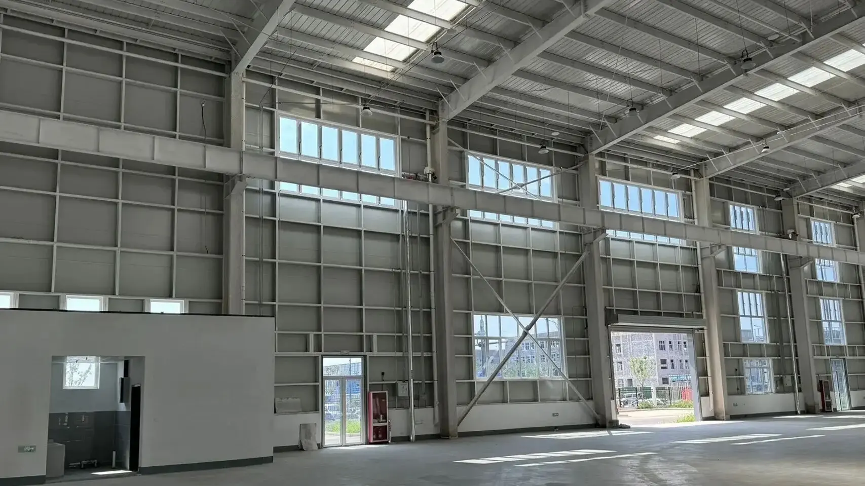
Prefabricated Steel Structure Workshop with Overhead Crane: Buyer’s Guide to Specs & ROI
Specify a prefabricated steel structure workshop with an overhead crane using a buyer-side framework: how wheel loads and duty class govern the frame, runway beam and bracket detailing, anchor-bolt and foundation tolerances, cost and ROI drivers from USD/ton and kg/m² benchmarks, and a nine-point supplier scorecard built on AISC 360-16, EN 1090-2 and AWS D1.1 evidence.

Specialist in crane-served steel workshops, runway beam and bracket detailing, and overseas turnkey delivery at Jinan XinQiao Steel Structure Co., Ltd.
Table of Contents & Quick Navigation
Quick answer: Can a prefabricated steel workshop support an overhead crane?
Yes, a prefabricated steel structure workshop with overhead crane is feasible, but only when the building is engineered as a crane building from the start. The overhead crane is a governing load case, not an accessory. Runway beams and columns must be designed as one crane-support system. Bracing and foundations must follow the same crane load path. This is a safety-critical, project-specific decision, not a catalog option.
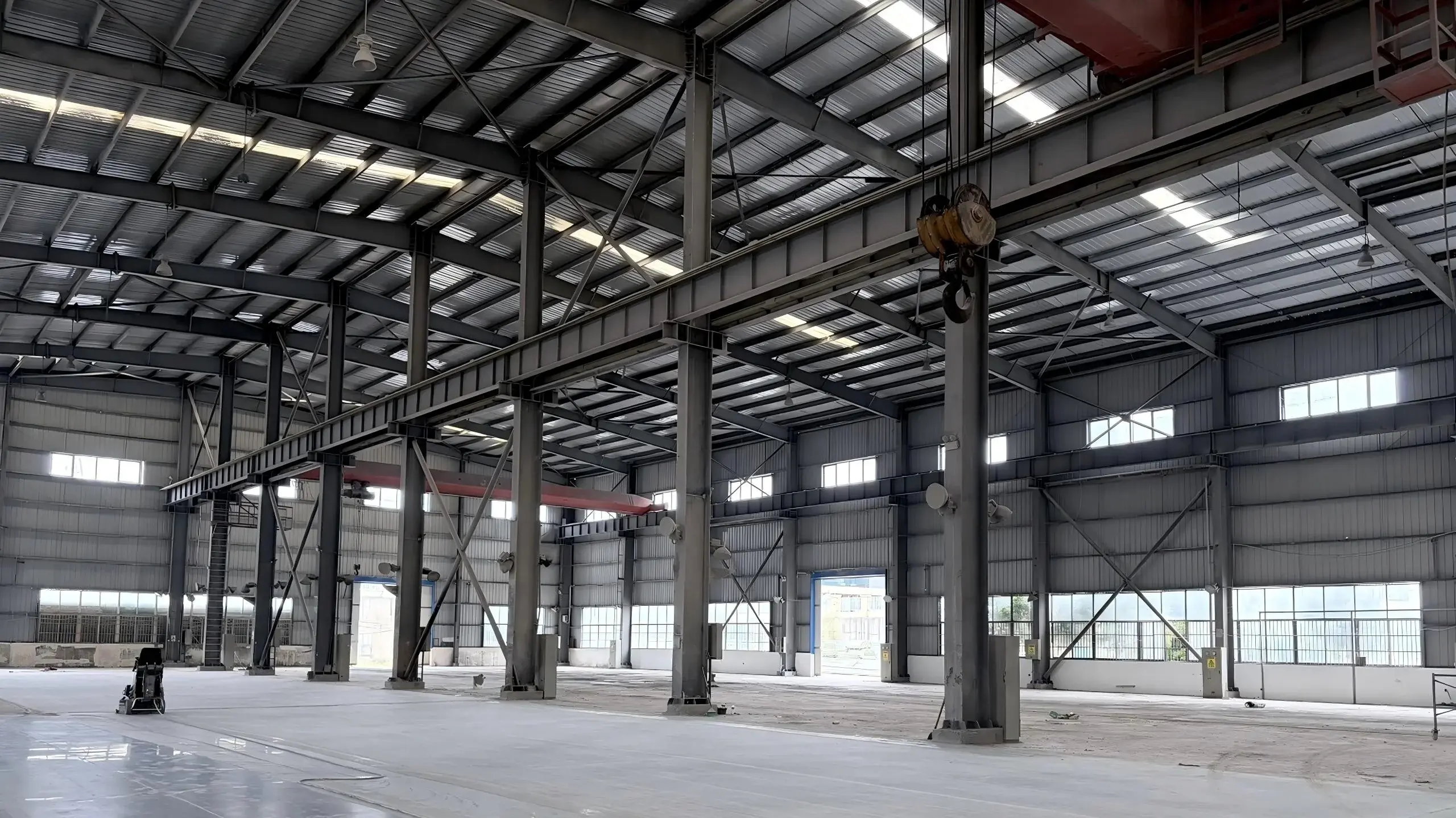
Five buyer inputs control feasibility:
Table T1. Buyer inputs that control crane-workshop feasibility
| Buyer input | Engineering consequence |
|---|---|
| Crane capacity | Sets runway girder and bracket demand; column demand follows from those reactions. Confirm lifted load plus trolley and spreader. |
| Crane span | Fixes runway beam depth, column spacing, and lateral bracing layout. |
| Lifting height | Controls column height, hook approach, and roof clearance. |
| Duty class | Drives fatigue details, wheel loads, and connection toughness; state ISO 4301 or CMAA class. |
| Runway and foundation requirements | Defines anchor bolt layout to AISC Design Guide 1 Section 2.3, field tolerance ±3 mm, base plate size, and concrete interface. |
Workshop tolerances: CNC plasma cutting ±0.5 mm, Sa 2.5 blast cleaning to ISO 8501-1, 80 µm epoxy zinc-rich primer DFT. Specify Q355B or ASTM A992 steel and weld to AWS D1.1; execute to EN 1090-2. Check runway beam design to AISC 360-16. Use the selection matrix and supplier checklist to compare crane-ready quotes.
Overview: What is a prefabricated steel structure workshop with an overhead crane?
A prefabricated steel structure workshop with overhead crane is an integrated crane-building system: primary steel frame in Q355B or ASTM A992, crane runway beams, crane brackets, columns, anchor bolts, foundation interface, and the overhead crane share one design scope. It is not a generic steel warehouse with a crane added after award. Crane wheel loads, fatigue cycles, runway alignment, and anchor bolt setting govern frame and connection design. These items are project-specific and require stamped structural and foundation design. Prefabrication affects shop fabrication and site bolt-up only; it does not remove the need for project-specific engineering.
Table T2. Purpose-built crane workshop versus a warehouse with a crane added later
| Buyer decision metric | Purpose-built integrated crane workshop | Generic warehouse with crane added later |
|---|---|---|
| Structural design basis | Crane loads and fatigue included at bid stage | Roof and wind loads normally govern; crane check comes late |
| Runway beams and brackets | Shop-fabricated with frame; trial-fitted before shipment | Field-fitted brackets and shims increase fit-up risk |
| Anchor bolts and foundation | Coordinated to crane supplier layout; ±3 mm setting tolerance | Coring, grouting, or rework may be needed |
| QA and handover | AWS D1.1 welds, EN 1090-2 execution, AISC Design Guide 1 Section 2.3 anchor bolt checks | Interface responsibility often split across suppliers |
| Export packing and lead time | 40HQ bundle and dunnage plan fixed during fabrication; typical 25-45 day fabrication window | Packing and crane interface confirmed after warehouse award |
Shop data used for proposal review: CNC plasma cutting tolerance ±0.5 mm, Sa 2.5 blast cleaning, epoxy zinc-rich primer 80 µm DFT. Factory acceptance should review dimensional reports, weld maps, bolt-hole alignment, and coating records before shipment. Use $/ton and $/square meter benchmarks, and require a line-item split for frame steel, runway steel, crane, anchor bolts, and erection. This guide is for buyers, plant engineers, project managers, and procurement teams comparing proposals.
How overhead crane loads govern the steel frame
For a prefabricated steel structure workshop with overhead crane, the runway is a primary load-bearing system. The frame cannot be sized from building span alone because the crane vendor's wheel loads, wheelbase, surge forces, traction forces, duty class, and impact allowance dictate runway beam depth, bracket stiffening, column section, base plate thickness, anchor bolt diameter, and foundation reinforcement. A 30 m span with a light roof and a 50 t crane requires a different frame than the same span with a 5 t crane.
The load path starts at the bridge wheel: vertical wheel load plus impact enters the runway beam, transfers through the runway bracket and its stiffeners into the column, then through the column base plate into anchor bolts and the concrete foundation. Horizontal surge loads act transverse to the runway and load the column weak axis. Longitudinal traction acts along the runway and loads the bracket-to-column connection and base shear system. Repeated crane cycles add fatigue checks at weld details and local plate connections, with duty class setting the required detail category.
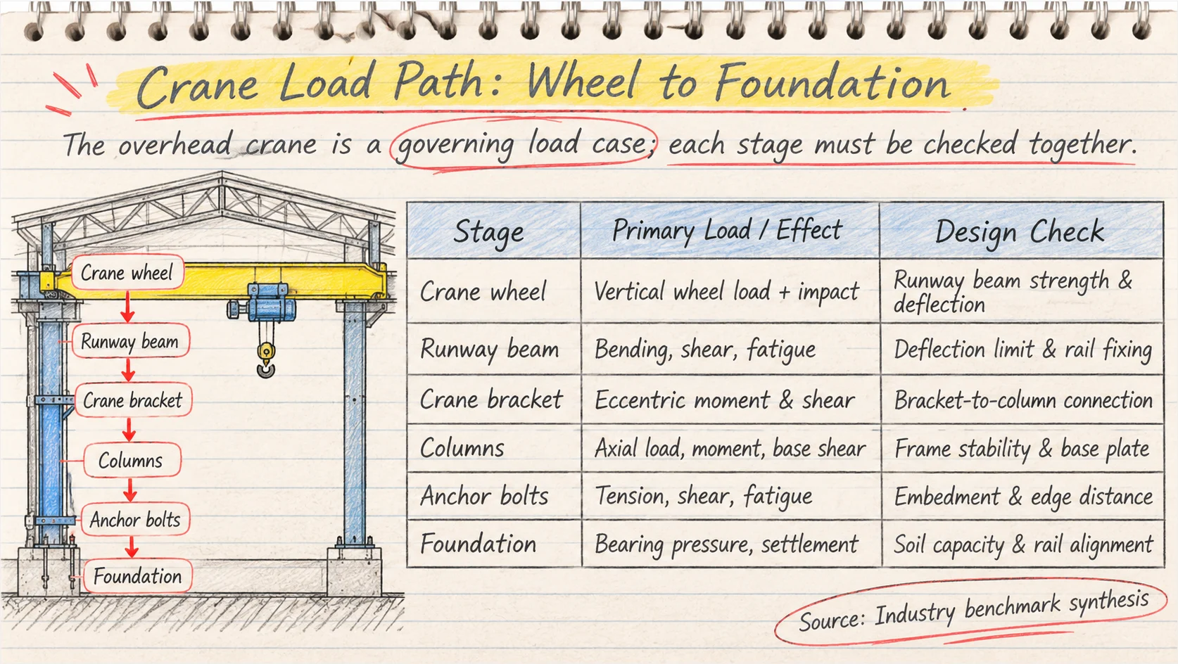
Workshop tolerances and QA values must be fixed before pricing: CNC plasma cutting ±0.5 mm, Sa 2.5 blast cleaning, epoxy zinc-rich primer 80 µm DFT, anchor bolt template layout ±3 mm. Bracket welds follow AWS D1.1; execution follows EN 1090-2. Base plate and anchor design follows AISC Design Guide 1 Section 2.3; member checks follow AISC 360-16 Chapter H for combined forces. These are safety-critical interfaces, and a generic span-based quote misses them.
Table T3. Crane load design checks and procurement decision metrics
| Load case | Primary frame check | Procurement metric | Verification |
|---|---|---|---|
| Vertical wheel load plus impact | Runway beam flexure, web stiffener, bracket bearing | Q355B or ASTM A992 plate thickness, $/ton cost basis | AISC 360-16 Chapter F; AWS D1.1 |
| Horizontal surge | Column weak-axis capacity, bracket weld | Column mass, bolt-up erection hours | AISC 360-16 Chapter H |
| Longitudinal traction | Bracket-to-column connection, base shear | Anchor bolt diameter, template tolerance ±3 mm | AISC Design Guide 1 Section 2.3 |
| Fatigue and duty class | Weld detail, local plate stress | Fit-up QA, 80 µm DFT primer, fabrication lead time | ISO 4301; EN 1090-2 |
Use Table T3 to compare crane reactions and commercial scope before releasing fabrication. Runway beams over 12 m typically need 40HQ bundling and dunnage planning, while bracket assemblies ship knocked down for bolt-up erection; factory acceptance checks include cut tolerance ±0.5 mm, weld visual per AWS D1.1, primer DFT 80 µm, and anchor template ±3 mm. The engineer must apply project-specific load combinations from ASCE 7-16 Section 2.3 and the crane vendor's actual reactions, not a catalog span table. A frame package that omits surge and traction is not reviewed for the real crane duty. Impact and duty class must also be included in that review.
Crane types and workshop configurations
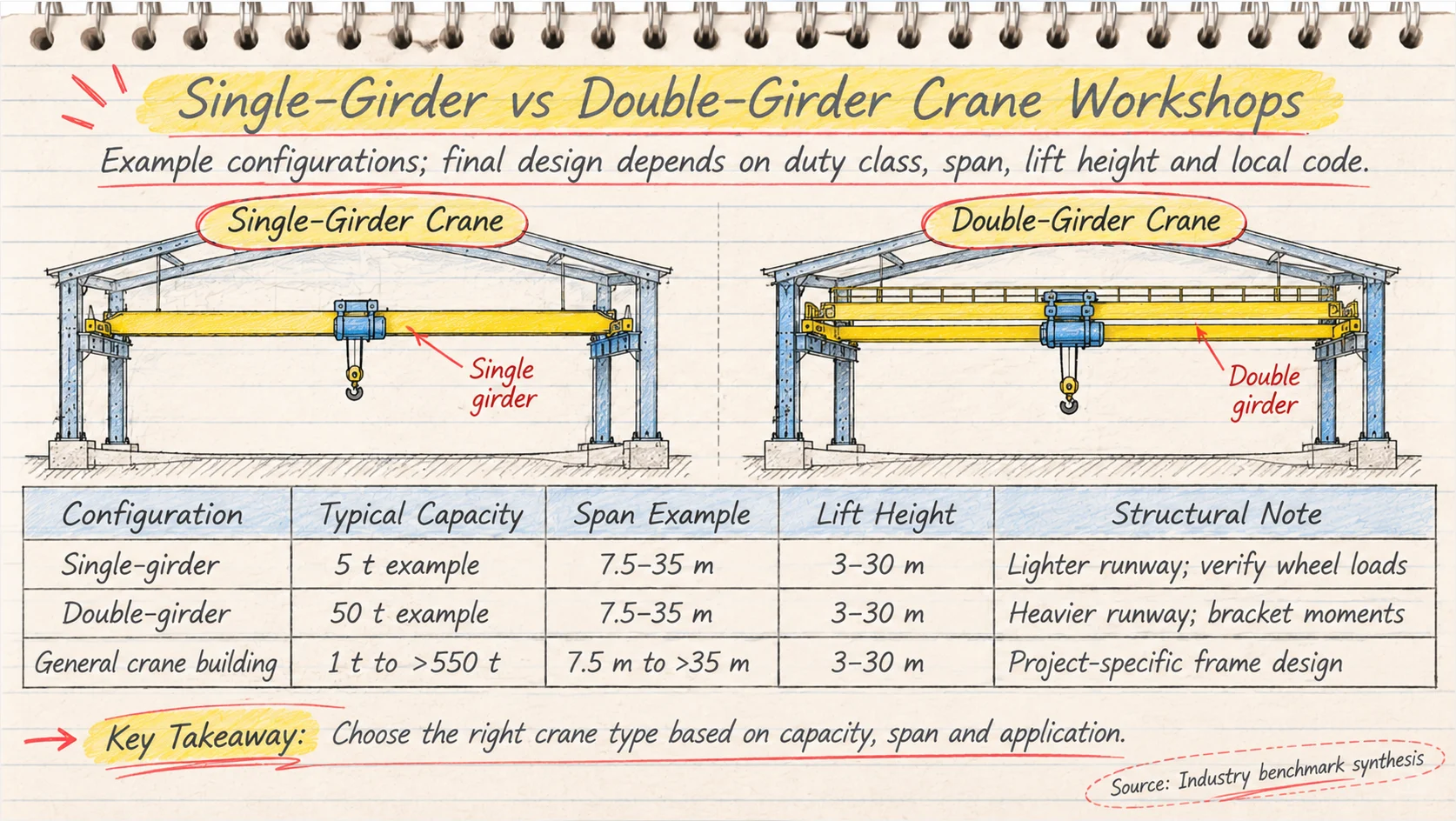
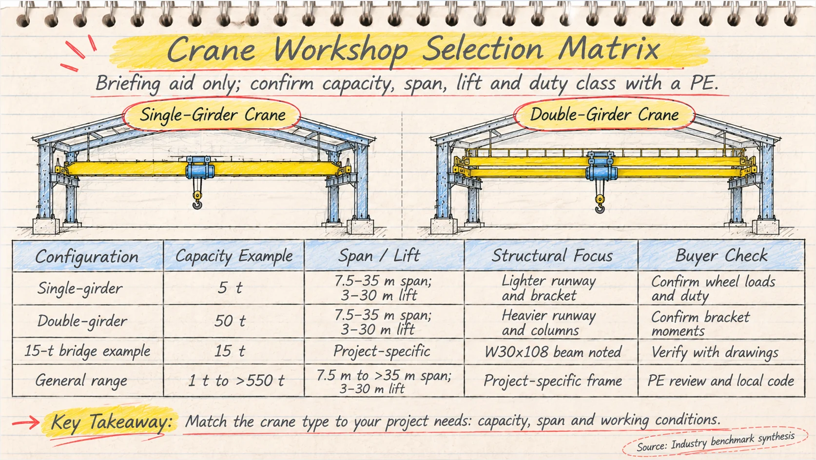
A prefabricated steel structure workshop with overhead crane requires crane duty, hook approach, and runway elevation to be fixed before the column grid and crane girder details are released to fabrication. The choice between single-girder and double-girder cranes changes runway bracket eccentricity, crane girder depth, and column bracing. Top-running and under-running arrangements change headroom and roof framing. Electric overhead traveling (EOT) cranes with a top-running trolley are often specified for heavier duty cycles; single-girder hoist arrangements are often used where lower capacities and tighter headroom suit the process. Confirm crane manufacturer data for wheel loads and clearances before structural release.
Table T4. Crane configurations and their structural consequences
| Configuration | Typical example capacity, verify by project | Structural effect | Procurement check |
|---|---|---|---|
| Single-girder top-running with hoist | 1 to 16 t, spans 10 to 25 m | Lighter crane girder and runway beam on column brackets; check wheel load eccentricity | Confirm hoist hook approach and runway beam connection detail |
| Double-girder top-running EOT | 5 to 50 t, spans 15 to 35 m | Deeper crane girder, larger runway bracket, heavier column and foundation loads | Obtain wheel loads, end carriage dimensions, and buffer clearances |
| Under-running crane or monorail hoist | 0.5 to 10 t, short bay spacing | Saves headroom; loads transfer to roof or runway support beam; check lateral bracing | Verify suspension detail and roof member capacity |
| Future expansion bay | Add 1 to 2 bays or a future crane bay | Isolate future runway columns; provide bolted extensions; reserve anchor bolt pattern | Freeze column line and crane rail elevation for expansion |
Capacity, span, lifting height, and bay spacing are coupled. A longer span increases crane girder depth and column moment; higher lifting height raises the runway elevation and roof eave. Wider bay spacing can reduce column count but increases crane girder and runway beam sizes. For future expansion, keep the crane runway module and column base plate layout consistent; provide bolted splice details and a documented anchor bolt template at ±3 mm layout tolerance.
The fabrication contrast is visible in Figure 3: single-girder hoist runway bracket versus double-girder EOT crane girder.
Fabrication QA/QC follows the approved inspection and test plan: mill certificates to EN 10204 3.1, CNC plasma cutting at ±0.5 mm, fit-up and AWS D1.1 weld inspection, and dimensional checks before Sa 2.5 blast cleaning and epoxy zinc-rich primer at 80 µm DFT. Crane girders commonly use ASTM A992 or Q355B plate in 10 mm to 30 mm thickness. Runway bracket and anchor bolt design are checked under AISC Design Guide 1 Section 2.3 and AISC 360-16 Table C-B4.1E, with EN 1090-2 execution requirements where the project specifies CE marking. Structural release requires project-specific engineering review.
Table T5. Commercial decision metrics for crane-served workshops
| Commercial decision metric | Example range for budgeting, verify by project | Release condition |
|---|---|---|
| CapEx benchmark | Fabricated steel supply USD 1,300 to USD 2,300 per ton; erected shell USD 45 to USD 95 per sqm, excluding crane and foundations | Compare scope, coating, freight, and erection labor |
| Fabrication lead time | 4 to 8 weeks after approved shop drawings and mill release; crane girders and runway brackets may add 1 to 2 weeks | Check mill allocation and weld procedure qualification |
| Sea freight containerization | 40HQ bundles at 26 to 28 t payload, dunnage and saddle packing; long crane girders may require 40FR or breakbulk | Confirm bundle length, center of gravity, and port crane capacity |
| Bolt-up erection | Primary frame example 150 to 300 sqm per day with 6 to 10 workers, depending on access and crane | Require bolt tensioning procedure and plumb tolerance plan |
| QA/QC and fabricator vetting | ISO 9001, EN 1090-2 EXC2, AWS D1.1 welders, third-party inspection, project references | Audit mill certs, welder qualifications, dimensional reports, and coating DFT records |
Benefits and trade-offs of integrated crane-building design
An integrated crane-building design for a prefabricated steel structure workshop with overhead crane ties runway beams, crane columns, roof bracing, and base plates into one load path. The benefits are procurement consequences: fewer separate runway columns, one fabricator owning crane brackets and rail clips, and a continuous load path to anchor bolts set at ±3 mm. Engineering claim: when wheel loads and duty class are frozen before column sizing, Q355B or ASTM A992 runway brackets commonly use 20 mm to 25 mm plate and avoid duplicate column lines. Cost assumption: FOB China fabrication for primed Q355B crane buildings commonly falls in USD 1,350 to 1,950 per metric ton, with installed cost project-specific.
Table T6. Benefits of an integrated crane-building scope
| Benefit | Design consequence | Procurement consequence |
|---|---|---|
| Steel member optimization | Runway beam and column sized as one frame under AISC 360-16 strength and serviceability checks | Lower tonnage and fewer 40HQ bundles; release mill order only after shop drawing approval |
| Interface risk reduction | One fabricator owns crane brackets, rail clips, tie-back connections, and base plates | Fewer RFIs during bolt-up erection; AWS D1.1 weld map included in FAT package |
| Load-path continuity | Crane surge transfers through roof bracing to anchor bolts | Foundation contractor uses fabricator templates; 100% anchor bolt survey before grout |
| Crane operation safety | Wheel load, hook approach, and clearance fixed in the structural model | Crane supplier confirms loads before design freeze; no late runway beam changes |
| Erection schedule | Bolted connections reduce field welding | A 2,000 sqm package typically needs 8 to 12 days for bolt-up plus 3 days for crane bracket welding |
The trade-offs are real. Integrated design adds 3 to 4 weeks of connection detailing and foundation coordination before mill order. Foundation sensitivity rises because crane overturning moments drive base plate and anchor design under AISC Design Guide 1 Section 2.3 and ACI 318 breakout checks. Duty class changes from A5 to A7 per ISO 4301-1 can force thicker brackets and EN 1090-2 EXC3 welding. Future expansion is limited by fixed runway bracing and column spacing. Coordinated fabrication is required: CNC plasma cutting at ±0.5 mm, Sa 2.5 blast cleaning to ISO 8501-1, epoxy zinc-rich primer at 80 µm DFT, and 10% UT on full-penetration runway bracket welds are FAT hold points.
Table T7. Trade-offs, release controls, and commercial effects
| Trade-off | Release control | Commercial effect |
|---|---|---|
| Upfront engineering | Freeze wheel loads, duty class, and anchor bolt layout before mill order | 3 to 4 week engineering add; fabrication 6 to 9 weeks after approved shop drawings |
| Foundation sensitivity | Complete base plate and anchor breakout checks before concrete pour; verify anchor bolts at ±3 mm | Concrete pour cannot start early; reduces grout and alignment claims |
| Crane duty class | Confirm A5 to A7 classification to ISO 4301-1 and weld details to AWS D1.1 | Higher duty class adds weld volume and inspection hours |
| Future expansion | Set bolted end-plate connections and spare anchor bolt sleeves at planning stage | Lower future crane span change cost; may add minor steel cost now |
| Fabrication coordination | Vet fabricator for EN 1090-2 EXC3, AWS D1.1 welder records, and CNC plasma report | Single 40HQ package with 11.8 m splices and 150 mm dunnage clearance; fewer field fit issues |
The correct procurement decision is to freeze crane duty, wheel loads, and foundation interface before releasing the fabrication package. This crane-building scope can deliver lower installed cost, but only when engineering and fabrication are coordinated before the first plate is cut.
A smaller ask
If a full quotation is premature, send us your bay spacing, clear span, and eave height, together with the crane capacity and duty class you are planning for. Our engineering team will return a preliminary frame layout and connection logic review so you can test the concept before committing to a broader package. Request a preliminary workshop frame review with the technical desk at Jinan XinQiao.
Specifications and selection matrix: capacity, span, lifting height, and duty class
Every prefabricated steel structure workshop with overhead crane is a custom frame, and the crane data package drives the steel tonnage. Table T8 is the buyer-side matrix we use to convert an operating requirement into a bid-ready scope. It captures the nine inputs that move column sections, runway beam mass, and foundation cost, and it fixes what the fabricator must confirm before quoting.
Table T8. Buyer selection matrix for crane-served steel workshops
| Input parameter | Typical working range | What it controls | Submit with RFQ |
|---|---|---|---|
| Rated capacity | 5 t to 100 t; single girder common to 20 t | Girder depth, wheel loads, runway beam section | Maximum load, crane dead weight, wheel base, maximum wheel load |
| Span | 12 m to 36 m | Frame type, column section, roof bracing layout | Rail center to rail center dimension |
| Lifting height | 6 m to 30 m hook height | Eave height, column length, hook approach | Hook height above finished floor, required end approach |
| Duty class | A3 to A7 (FEM M4 to M7) | Fatigue detail category, weld quality, wheel hardness | Cycles per hour, hours per day, load spectrum |
| Crane type | Top running single or double girder, underslung | Bracket detail, runway geometry, available headroom | Crane make and model, or leave open for design |
| Building clear height | Eave height less runway beam and crane envelope | Column height, girt spacing, cladding quantity | Minimum clearance below hook and below roof purlin |
| Bay spacing | 6 m to 12 m | Purlin span, number of braced bays, column base count | Preferred module, door positions, crane access zones |
| Runway deflection criterion | L/600 cab operated, L/400 pendant, per AISC Design Guide 7 | Runway beam depth, column stiffness | Client limit where stricter than the above |
| Future load allowance | 10 percent to 20 percent on crane and roof loads | Reserve capacity in columns and foundations | Planned second crane or capacity upgrade |
Published supplier tables give capacity and span envelopes. They are starting points, not designs. A 20 t crane at 30 m span in class A6 pushes far more steel into the runway beam and bracket than the same capacity at 15 m in A4. Column demand also rises, and that difference appears as plate thickness and base plate area rather than in any catalog line.
Data to collect before requesting a proposal: rated capacity and duty class from the production plan, rail span, hook height and approach, wheel loads and wheel base from the crane maker, eave and clear height, bay module, roof and wall dead loads including suspended services, anchor bolt constraints, and wind and snow parameters. Also collect seismic parameters and the rail section (A55 to A75 per ASTM A759).
Checks that must return in the proposal: framed column and runway beam design to AISC 360-16 Chapter F, fatigue verification to AISC 360-16 Appendix 3, column base plate sizing to AISC Design Guide 1 Section 2.3, weld design and inspection to AWS D1.1 Clause 6, and execution class EXC3 per EN 1090-2 for runway girders. Structural plate is Q355B to GB/T 1591 or ASTM A992 where specified. Shop work must state CNC plasma tolerance of plus or minus 0.5 mm, Sa 2.5 blast cleaning, 80 µm zinc-rich primer DFT, and anchor bolt layout within plus or minus 3 mm.
Runway beams, brackets, columns, and anchor bolts
A prefabricated steel structure workshop with overhead crane succeeds or fails on four members that carry the trolley load: the runway beam, the corbel bracket, the crane column, and the anchor bolt group. Buyers spend weeks comparing member weights and almost no time reviewing weld details, base plate grouting, or bolt embedment tolerances. The second group is what determines whether the crane tracks true for 25 years or develops wheel flange wear and rail misalignment within two seasons.
Runway beams are commonly welded I-sections in Q355B (ASTM A992 equivalent) with web plates from 8 mm to 16 mm and flanges from 12 mm to 30 mm, sized for the wheel load path rather than for simple bending alone. Vertical deflection limits in most project specifications follow CMAA 74 and AISC Design Guide 7: L/600 for cab-operated cranes, L/500 for pendant-controlled units. Lateral deflection typically holds at L/400. Fatigue governs the bracket connection detail, and AISC 360-16 Appendix 3, Table A-3.1E assigns stress category E or E′ to welded corbel-to-column joints, which caps the allowable stress range and usually sets the weld size, not the member weight.
Lateral restraint of the top flange deserves attention during erection, not after. Tie-backs to roof purlins or a longitudinal bracing line must be installed before the crane is commissioned; an unrestrained top flange under eccentric wheel load rotates the section and misaligns the rail. Corbel brackets require full-depth bearing stiffeners aligned with the column flange, plus intermediate stiffeners where the reaction exceeds the web crippling capacity. Column base moments from crane surge and traction transfer through the anchor bolts as uplift, and AISC Design Guide 1 Section 2.3 governs the base plate and bolt design. Anchor bolts in ASTM F1554 Grade 36, 55, or 105 require concrete breakout checks to ACI 318-19 Chapter 17, and shear transfer relies on base plate friction plus a shear lug when friction alone is insufficient. Non-shrink grout to ASTM C1107 at 50 mm minimum thickness completes the load path; a starved or dry-packed grout pad under a crane column is a common field defect.
Fabrication tolerances hold the assembly together. Anchor bolt templates are set to plus or minus 3 mm, bolt holes to plus or minus 1.5 mm, and CNC plasma cuts to plus or minus 0.5 mm. Plates are blast cleaned to Sa 2.5 and primed at 80 µm DFT epoxy zinc-rich before shipment. Runway and column tonnage typically represents 12 to 18 percent of total frame weight, so connection quality carries disproportionate commercial risk relative to cost.
Table T9. Runway and connection design checklist
| Checkpoint | Accept value | Verification stage |
|---|---|---|
| Runway vertical deflection | L/600 cab-operated, L/500 pendant | Design review |
| Top flange restraint spacing | Matches brace design, installed before crane load test | Site inspection |
| Corbel stiffener alignment | Full-depth, aligned to column flange centerline | Shop drawing |
| Bracket groove weld | CJP, AWS D1.1 qualified, UT per EN 1090-2 EXC3 | Factory QA |
| Anchor bolt layout | Plus or minus 3 mm from template | Pre-pour survey |
| Anchor bolt grade and embedment | ASTM F1554 Gr 55, breakout checked to ACI 318-19 Ch. 17 | Design review |
| Grout pad | ASTM C1107, 50 mm minimum, full bearing | Site inspection |
| Base plate shear transfer | Friction plus shear lug where required | Design review |
Foundation, settlement, and rail alignment requirements
Foundation design must be completed with the steel structure design for any prefabricated steel structure workshop with overhead crane. Crane runway loads govern the column base. Vertical reactions come from roof and wall loads and from the crane. Horizontal surge and traction forces act at the base. Column base moments come from crane eccentricity. These actions set anchor-bolt tension and shear demand. They also set embedment and concrete breakout demand. AISC Design Guide 1 Section 2.3 and ACI 318-19 Chapter 17 provide the base plate and anchorage checks. Do not release column base plates for fabrication until foundation reactions and anchor-bolt templates are coordinated. Concrete capacity must be confirmed at the same time. A pre-pour survey of anchor-bolt layout at ±3 mm is cheaper than post-pour remedial work.
Settlement control is a crane safety issue. Differential settlement across the crane span changes rail gauge and rail top elevation, causing wheel flange contact, rail wear, and crane skew. Specify project-specific differential settlement limits in the foundation drawing and verify them with a post-erection survey. Use non-shrink grout under base plates with a controlled thickness and cure period. Anchor bolts should be ASTM F1554 Grade 55 or project-specified equivalent, with projection and embedment checked against the approved shop drawing.
Fabrication and field tolerances must be stated before award. CNC plasma cutting at ±0.5 mm, Sa 2.5 blast cleaning, and 80 µm zinc-rich primer DFT apply to steel; foundation tolerances apply to civil works. Typical field targets are anchor-bolt layout ±3 mm, bolt projection ±5 mm, base plate level ±2 mm, rail gauge ±3 mm, and rail top elevation ±5 mm. EN 1090-2 execution tolerances and AISC 360-16 Table C-B4.1E provide the reference framework.
Table T10. Foundation and anchor-bolt data checklist
| Checkpoint | Required data | Acceptance or tolerance | Verification stage |
|---|---|---|---|
| Design reactions | Vertical, horizontal surge, traction, base moment | Matches foundation and anchor-bolt design | Design review |
| Anchor bolts | Diameter, grade, embedment, projection, template | Layout ±3 mm; projection ±5 mm | Pre-pour survey |
| Concrete capacity | Footing size, concrete strength, reinforcement, breakout check | ACI 318-19 Chapter 17 compliance | Pour inspection |
| Settlement | Allowable differential settlement across crane span | Project-specific limit | Post-erection survey |
| Rail alignment | Gauge, elevation, straightness | Gauge ±3 mm; elevation ±5 mm | Laser survey |
| Grouting | Non-shrink grout, thickness, cure | Full bearing under base plate | Post-grout check |
Weak foundations cause rail misalignment and crane safety risks. Table T10 is the pre-pour and post-grout checklist used to hold anchor-bolt layout, base plate bearing, and rail alignment inside tolerance before the crane is commissioned.
Steel consumption, cost, and ROI drivers
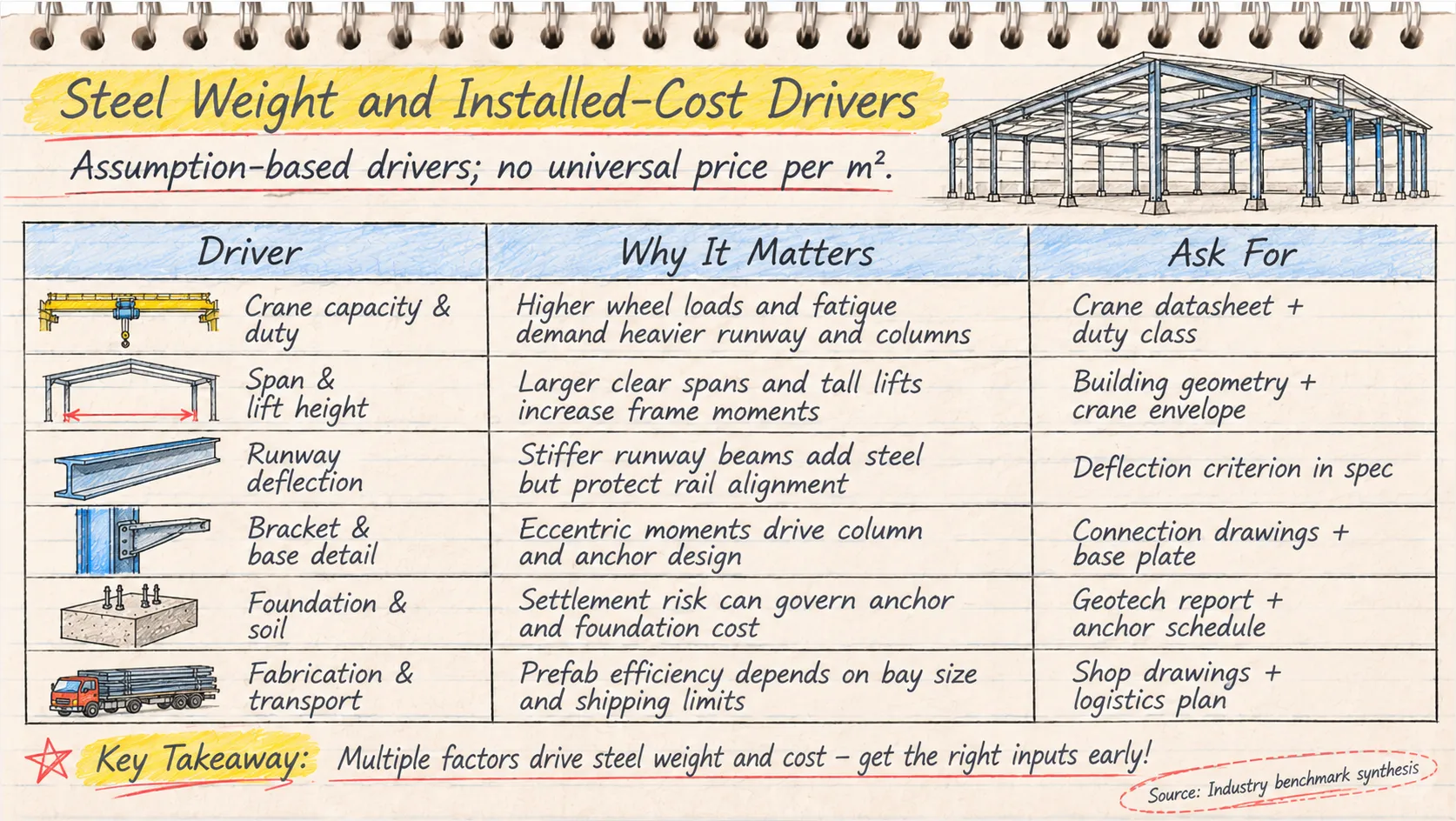
A prefabricated steel structure workshop with overhead crane is a load-path purchase, not a floor-area purchase. Budget estimates that start from building size alone miss the crane runway and bracket eccentricity. They also miss foundation reactions that set member mass. For early-stage planning, furnished structural steel for a 20 t single-girder crane workshop commonly falls between US$1,450 and US$2,200 per metric ton ex-works China. That band assumes Q355B or ASTM A992 plate and sections, CNC plasma cutting at ±0.5 mm, Sa 2.5 blast cleaning, 80 µm epoxy zinc-rich primer dry film thickness, AWS D1.1 welds, and EN 1090-2 EXC2 fabrication. Cladding and erection are excluded. Freight and piling are excluded.
Table T11. Decision metrics for steel consumption and cost
| Driver | Effect on steel mass and cost | Estimating checkpoint |
|---|---|---|
| Crane capacity and duty class | Higher capacity and heavier duty class increase runway beam, bracket, and column demand; A5 medium duty often needs less mass than A7 heavy duty at the same lift | Confirm duty class and wheel loads |
| Span and lifting height | Long clear spans raise rafter depth and column moment; extra height increases cladding area and wind exposure | Compare 24 m, 30 m, and 36 m options against internal traffic layout |
| Bay spacing and runway beam design | Wider bays reduce column count but increase crane girder span and deflection control demand; runway beam depth often governs steel mass | Check crane girder deflection limit and tie-back bracing with AISC Design Guide 1 Section 2.3 |
| Foundation scope | Crane loads and uplift set anchor bolt layout and pedestal size; anchor bolt layout tolerance is typically ±3 mm | Include anchor bolt templates in the fabrication package |
| Cladding and envelope | Insulated sandwich panels or single skin change purlin spacing and secondary steel mass | Fix U-value and fire rating before tender |
| Freight and erection | 40HQ container bundling and dunnage efficiency affect landed cost; bolt-up erection speed depends on connection detailing | Request loading plans and trial assembly records |
| Local market conditions | Plate mill lead time and galvanizing capacity move the final number; labor rates are quoted separately | Quote with a stated validity period and currency basis |
Steel consumption follows load path efficiency. A 30 m span with a 32 t crane may consume 55 to 75 kg/m² of primary frame, while a 24 m span with a 10 t crane and tighter bay spacing can sit near 35 to 45 kg/m². These are planning bands, not fixed quotations. ROI ties to uptime and throughput. Safety and future flexibility also matter: a properly sized runway beam reduces wheel load maintenance, and a clear crane envelope protects cycle time. A 1.5 m future hook height allowance avoids a later column retrofit.
Applications and fit-out considerations
A prefabricated steel structure workshop with overhead crane fits manufacturing workshops, fabrication bays, assembly buildings, maintenance shops, warehouses with lifting requirements, and heavy-equipment service buildings. Project-specific crane duty changes the frame. A 10 t light-duty maintenance crane at 6 m lift may use Q355B columns at 8 m spacing; a 50 t heavy-duty fabrication bay at 12 m lift often needs built-up columns, runway beams at 1.2 m depth, and a column grid at 6 m to 7.5 m. Fit-out decisions then lock into steel: clear height sets hook approach and roof truss depth; crane coverage sets runway length and end stops; door locations set bracing bays; mezzanines add column loads; fire protection and ventilation ducts consume truss zone; lighting and future equipment changes require spare runway capacity and service loads. Anchor bolt layout tolerance is ±3 mm under AISC Design Guide 1 Section 2.3.
For any prefabricated steel structure workshop with overhead crane, procurement benchmarks follow the same fit-out scope. Fabricate to AWS D1.1 and EN 1090-2 EXC2, with Sa 2.5 blast cleaning and epoxy zinc-rich primer at 80 µm DFT. Verify CNC plasma cutting at ±0.5 mm and heat numbers to ASTM A992 or Q355B.
Table T12. Procurement benchmarks for crane-served workshops
| Procurement metric | Benchmark for crane workshops |
|---|---|
| CapEx | USD 1,100 to 1,800 per ton fabricated; USD 95 to 160 per sqm erected shell |
| Fabrication lead time | 25 to 45 days after approved shop drawings |
| 40HQ loading | 18 to 24 t per container; bundle lengths under 12 m with dunnage at 1.5 m spacing |
| Bolt-up erection | 350 to 550 sqm per crew day for primary frame |
| QA checkpoints | AWS D1.1 weld inspection, EN 1090-2 EXC2 traceability, AISC 360-16 Table C-B4.1E bolt pretension check |
| Fabricator vetting | ISO 3834-2 certification, in-house plasma and shot-blast lines, heat-number records |
Code compliance, safety, and design coordination
Code compliance for a prefabricated steel structure workshop with overhead crane is a project-specific record, not a catalog certificate. The design basis must name governing code editions, occupancy, crane duty class, wind and seismic parameters, and the local permitting authority. A licensed PE reviews structural calculations, connection design, and foundation anchorage. Where wind or seismic loads govern, lateral bracing and base plate anchorage require site-specific verification. A generic statement of "AISC compliant" or "EN compliant" is not enough evidence for permitting or crane warranty.
Crane safety depends on hard clearances. Confirm hook height, end approach, rail stop position, buffer travel, operator access, maintenance walkway, and fall protection. Include rail stops and buffers in the crane interface drawing. Limit switches must also appear on that drawing. The crane supplier, structural engineer, foundation designer, and MEP team coordinate the crane envelope with sprinkler lines, lighting, ventilation, and cable trays. Foundation anchor bolts set to ±3 mm layout tolerance; column base grout and shim details belong on approved drawings.
Fabrication QA/QC uses measurable hold points: CNC plasma cutting ±0.5 mm, Sa 2.5 blast cleaning, epoxy zinc-rich primer 80 µm DFT, AWS D1.1 weld inspection, and EN 1090-2 execution tolerances. Structural steel may be ASTM A992 or Q355B, with connection checks per AISC 360-16 Table C-B4.1E and anchor bolt design per AISC Design Guide 1 Section 2.3, as specified by the project engineer. Procurement review should compare fabrication lead times and 40HQ loading plans; a low $/ton quote does not replace a stamped design package.
Table T13. Documents to request at permitting and release
| Document to request | Verify before approval | Hold point |
|---|---|---|
| Design calculations | Governing code edition, wind/seismic loads, crane loads, load combinations | PE stamp and project address |
| Approval drawings | Column grid, crane runway, bracing, clearances, MEP openings | Coordinated dimensions and revision control |
| Crane data | Duty class, wheel loads, hook height, end approach, stop and buffer dimensions | Supplier confirmation letter |
| Foundation design | Anchor bolt layout, base plate bearing, grout, drainage | ±3 mm bolt template check |
| Installation tolerances | Plumbness, elevation, bolt torque, weld acceptance | Site QA/QC checklist |
Supplier evaluation and procurement checklist
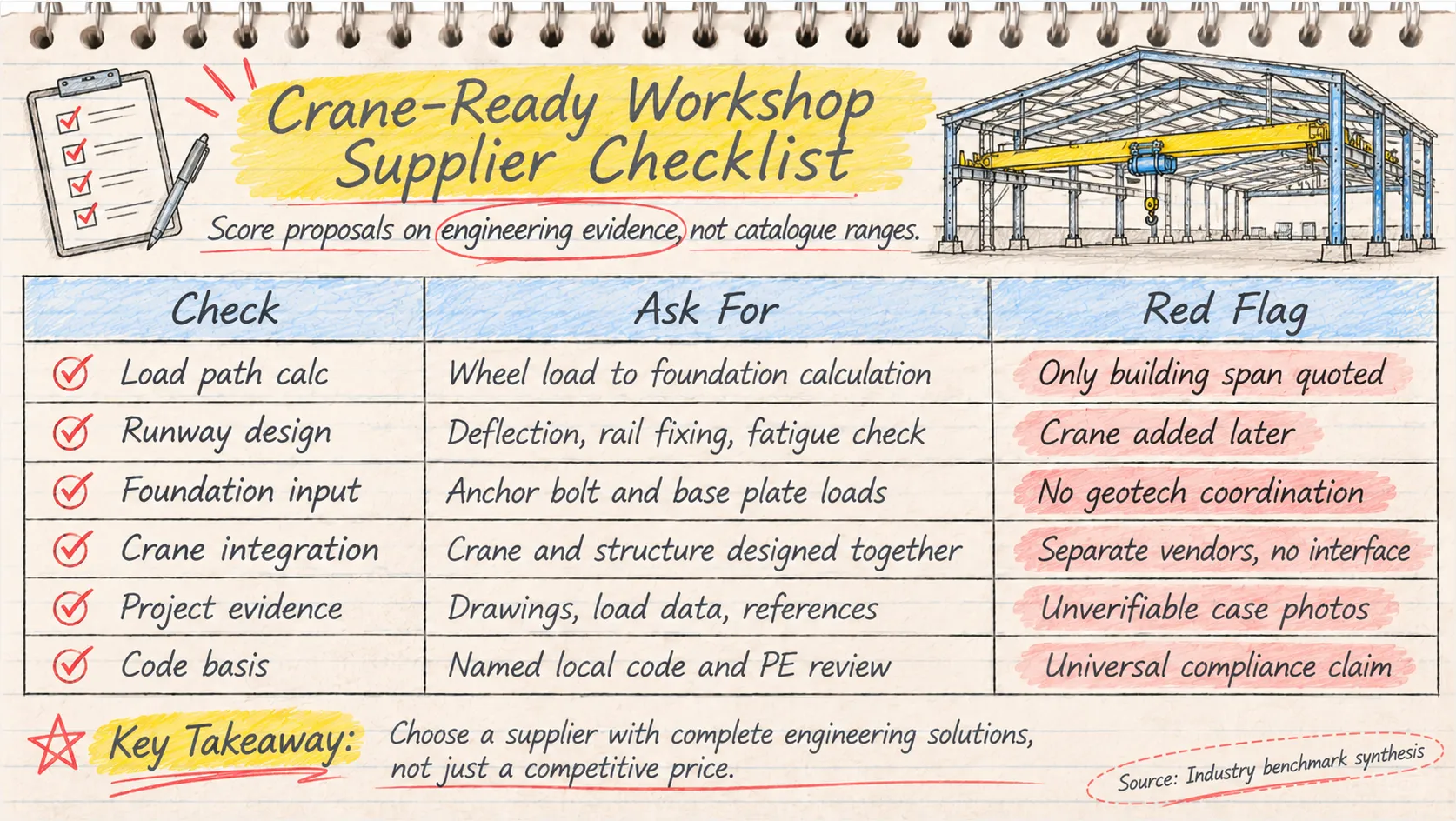
Vetting a prefabricated steel structure workshop with overhead crane supplier demands evidence of combined crane and building design, not a catalog of standard warehouse frames. Before any commercial comparison, request the crane duty class (FEM 9.511 or CMAA Class C), span, wheel loads, and runway beam deflection limit in writing. A supplier who cannot state these three parameters does not have a crane project to quote.
Engineering capability and load path verification
Require the structural calculation package in LRFD per AISC 360-16, including runway beam design to AISC Design Guide 7, fatigue check at the crane girder to column connection, and foundation reactions with assumed soil bearing capacity. Anchor bolt layout tolerance is ±3 mm on the template, and the column base plate detail must follow AISC Design Guide 1 Section 2.3. A fabricator that outsources these calculations without a named engineer of record carries design risk you will absorb.
Fabrication QA and drawing quality
Fabrication under EN 1090-2 EXC2 or AWS D1.1 with qualified welding procedures is the baseline. Confirm measurable shop controls: CNC plasma cutting tolerance of ±0.5 mm, SA 2.5 blast cleaning to ISO 8501-1, and epoxy zinc-rich primer at 80 µm DFT with a recorded batch certificate. Drawing quality shows in the connection details: bolt grades (ASTM A325 or A490), hole sizes, stiffener plates, and a trial erection of one bay before shipment. Manufacturer data on plate thickness and steel grade (Q355B or ASTM A992) must match the mill certificates.
Proposal scorecard
Table T14. Nine-point supplier proposal scorecard
| Evaluation criterion | Weight | Evidence to demand | Score 1 to 5 |
|---|---|---|---|
| Crane-structure integration | 20% | Duty class, span, wheel load, runway deflection limit stated | |
| Engineering and load calculations | 15% | Stamped LRFD package, foundation reactions, fatigue check | |
| Fabrication QA and welding | 15% | EN 1090-2 or AWS D1.1 certificates, DFT records, cutting tolerance | |
| Drawing and connection quality | 10% | Sample general arrangement and node details | |
| Project references with load data | 10% | Tonnage, span, duty class, country, client contact | |
| Installation support | 10% | Erection drawings, bolt-up sequence, supervisor days, torque values | |
| Lead time and logistics | 8% | Fabrication days, 40HQ bundle count, dunnage plan | |
| Warranty terms | 7% | Structural period, paint system period stated separately | |
| Cost transparency | 5% | Itemized $/ton or $/sqm with named exclusions |
Red flags that end the evaluation
- Crane capacity quoted in tons without span, duty class, or wheel load.
- No foundation assumptions: soil bearing capacity, anchor embedment depth, and grout specification absent.
- No runway deflection criterion, or a limit below L/400 for a CMAA Class C service.
- Case studies showing building area but no load data, span, or crane class.
Commercial transparency and lead time
Typical export pricing for this scope sits between USD 1,050 and USD 1,450 per ton FOB China for Q355B frames with a single-girder crane up to 20 t (cost assumption, 2025, excluding freight, foundation, and erection). Fabrication runs 45 to 75 days for 800 to 1,500 t, and a 40HQ container carries roughly 22 to 25 t of bundled members with proper dunnage. Ask each bidder to separate steel, freight, erection supervision, and warranty into line items, and to name every exclusion. Project-specific references from comparable crane spans are worth more than any brochure.
Project Evidence and Case-Study Criteria
A prefabricated steel structure workshop with overhead crane demands verifiable engineering evidence, not brochure claims. Buyers should request case studies that state crane capacity, span, lifting height, duty class (FEM 1Am to 3Am or CMAA Class C to D), building dimensions, foundation conditions, connection drawings, and load data. A 15-ton bridge crane using a W30x108 beam is a useful reference only when the runway girder design, wheel loads, and fatigue class are confirmed under AISC 360-16 Table C-B4.1E. Integrated 5-ton to 50-ton crane solutions require project-specific verification of runway alignment (anchor bolt layout tolerance ±3 mm), column stiffness, and crane stop forces.
Table T15. Marketing claims versus verifiable engineering evidence
| Verification item | Marketing claim (weak) | Engineering evidence (verifiable) | Acceptance check |
|---|---|---|---|
| Crane capacity and span | “Heavy duty crane ready” | Stamped runway girder drawing with wheel load schedule | Compare to crane vendor load curve |
| Building dimensions | “Large clear span” | Column grid, eave height, and crane hook height dimensions | Cross-check against architectural plan |
| Foundation conditions | “Simple foundation” | Anchor bolt setting plan and concrete design loads | Verify AISC Design Guide 1 Section 2.3 |
| Drawings and load data | “Full design package” | IFC drawings, connection details, AWS D1.1 weld maps | Third-party review before fabrication |
| Location and date | “Completed overseas project” | Named site, client contact, commissioning date | Request site visit or video audit |
| Measurable outcome | “High client satisfaction” | Erection cycle time, bolt-up tolerance report, QA/QC signoff | Confirm plasma cutting ±0.5 mm, Sa 2.5 blast, 80 µm DFT primer |
Distinguish claims from evidence: fabricated tonnage and completion date are project_specific; weld procedure qualification and mill certificates are manufacturer_data; deflection and crane fatigue limits are engineering_claim. Require a redacted contract page, load calculation summary, and EN 1090-2 execution class report. Marketing language without signed drawings or a verifiable site reference does not qualify as a case study.
FAQ
A prefabricated steel structure workshop with overhead crane is not a standard warehouse frame with a crane added later. Crane runway beams and their supporting columns carry wheel loads and surge loads set by the crane duty class, so frame, foundation, and connection design must be quoted together. Use the quick answers below, then confirm project-specific loads in crane runway design.
Table T16. Quick answers to the eight most common buyer questions
| Buyer question | Direct answer |
|---|---|
| Can a prefabricated steel workshop support an overhead crane? | Yes. Crane runway beams and their supporting columns must be designed for wheel loads and surge from the start; a standard warehouse frame is not adequate. See crane-ready framing. |
| What capacity, span, and lifting height are practical? | Common range: 5 t to 50 t, 10 m to 32 m crane span, 6 m to 18 m hook height. Above 50 t or 32 m, specify double-girder runway and fatigue checks. |
| What foundation and anchor-bolt information are needed? | Provide base reactions, anchor-bolt layout at ±3 mm, concrete strength, grout pad, and runway elevation. AISC Design Guide 1 Section 2.3 applies. |
| How does duty class affect steel consumption? | A7/M7 heavy duty can add 8% to 12% runway steel versus A5/M5 light duty at equal capacity because of fatigue details and beam size. State duty class in the RFQ. |
| Is single-girder or double-girder better? | Single-girder suits 5 t to 20 t and moderate duty. Double-girder suits heavy duty, long span, and high hook height. Confirm rail eccentricity with the crane supplier. |
| How long does design and construction take? | Design and shop drawings 2 to 4 weeks; fabrication 4 to 8 weeks for 1,000 t to 3,000 t; 40HQ sea freight 3 to 6 weeks; bolt-up erection 2 to 4 weeks for 3,000 sqm. See erection schedule. |
| How should buyers compare crane-ready workshop quotes? | Compare scope at equal duty: runway beams, rail, anchor bolts, Sa 2.5 blast, 80 µm DFT epoxy zinc-rich primer, AWS D1.1 welds, EN 1090-2 execution, and 40HQ bundle plan. Budget $1,050/t to $1,450/t FOB, project-specific. See quote comparison. |
| What QA/QC checkpoints matter before shipment? | Check CNC plasma cutting ±0.5 mm, hole layout, weld inspection, crane bracket trial fit, and anchor-bolt template before shipment. See QA/QC inspection. |
What is the maximum clear span for a pre-engineered steel warehouse?
Practical clear spans for pre-engineered warehouse frames are 18 m to 36 m. Spans of 40 m to 60 m need built-up rafters, trusses, or custom framing. For a crane-ready workshop, crane runway columns and hook coverage often set the clear span, not the warehouse frame alone. See clear-span limits.
How does clear-span width affect steel tonnage and building cost?
Tonnage rises as width increases because rafter depth, column size, and bracing demand more steel. A 24 m to 30 m frame commonly uses 8 kg/sqm to 14 kg/sqm more steel than an 18 m frame; 36 m and wider needs deeper sections. Cost per sqm can rise 5% to 15% per 6 m width step, depending on crane load and duty. See tonnage benchmarks.
What are the main structural limits of clear span prefab warehouses?
Main limits are rafter deflection, column base fixity, lateral bracing, crane eccentricity, and shipping envelope. AISC 360-16 Table C-B4.1E serviceability limits and AISC Design Guide 1 anchor settings control the design. Overhead crane adds fatigue checks to runway beams and connections. See structural limits.
How can tonnage and cost be optimized in large clear-span designs?
Use 6 m to 9 m bay spacing, Q355B or ASTM A992 plate grades, tapered rafters, and repeated bolted connections. Match crane duty to EN 1991-3 or CMAA duty, and avoid over-specifying hook height. Trial-fit crane brackets before shipment to reduce field rework. See cost optimization.
Next steps: specify a crane-ready workshop before you request quotes
A prefabricated steel structure workshop with overhead crane is governed by the runway and foundation interfaces. These interfaces are safety-critical. Lock the brief before pricing: crane capacity, span, lift height, and duty class (FEM/ISO or CMAA); wheel loads and end carriage data from crane manufacturer data sheets. Obtain project-specific geotechnical data, including boreholes with allowable bearing pressure and groundwater records. Require a load-path narrative that traces hook load through the runway beam and bracket. The narrative must continue through the column and bracing to the foundation. Ask for runway beam and foundation design assumptions, with anchor bolt layout tolerance of ±3 mm and foundation checks to AISC Design Guide 1 Section 2.3.
Use this quote-review table against Table T14:
Table T17. RFQ submittal checklist
| Submittal | Required evidence |
|---|---|
| Crane data | Capacity, span, lift height, duty class, wheel loads |
| Geotechnical | Boreholes, bearing capacity, groundwater |
| Load path | Runway beam to foundation narrative |
| Fabrication | Q355B/A992 certs, AWS D1.1 welds, Sa 2.5, 80 µm zinc primer DFT, FAT checkpoints |
| Commercial | $/ton and $/sqm breakdown, lead time, 40HQ bundle and dunnage plan, bolt-up erection days |
| Drawings | Stamped drawings or PE review where required |
Compare every proposal line by line against Table T14; reject missing runway beam or foundation assumptions. Submit crane data, geotechnical report, and site plan to Jinan XinQiao for a specification review before RFQ release.
Conclusion
Two numbers decide whether this workshop works: the wheel load the crane puts on each runway beam, and the bearing pressure the soil can return under the column base. Everything else in the frame follows from that path. Where the load path stays short and the duty class is modest, a 24 m span with a 10 t crane can sit near 35 kg/m² to 45 kg/m² of primary steel, while a 30 m span built around a 32 t crane commonly lands at 55 kg/m² to 75 kg/m². The gap between those bands is not decoration. It is bracket eccentricity, runway beam depth, column section and anchor bolt diameter doing their work.
Most quotes that look cheap are priced from span and eave height alone. They carry no wheel loads, no duty class, and no geotechnical bearing pressure, so the runway beam gets sized off a catalog table and the plus or minus 3 mm anchor bolt template never appears in the fabrication package. Fixing that after erection costs far more than the steel saved. Before you accept any number, ask for the crane vendor's actual wheel loads and duty class, then compare the cost per ton line by line inside one fixed scope of supply.
Engineering verdict
The governing decision is the crane load path, not the roof span. Wheel load plus impact, surge, and traction set runway beam depth, bracket eccentricity, column section, and anchor-bolt diameter before any architectural choice reaches the shop. A 24 m span carrying a 10 t crane lands near 35 to 45 kg/m² of primary steel; a 30 m span built for a 32 t crane sits at 55 to 75 kg/m², and the difference is fatigue detail and bracket stiffness rather than decoration. Where the runway and foundation interfaces are frozen before mill order, installed cost falls and the rail stays true; where they are priced later, the saving reappears as rework, grout repair, and crane skew.
Before you go
Before you release a crane-workshop package to tender, let our factory engineering desk check the frame geometry, crane loads, and connection details against your project basis. Jinan XinQiao operates a 60,000 sqm fabrication facility with automated CNC cutting lines and sub-millimeter tolerances, and our quality system is aligned with recognized ASTM/EN and EN 1090 requirements. Start a factory direct engineering review and receive a clear scope response from our technical team.
References
Base Plate and Anchor Rod Design (Second Edition)
Fisher, J. M., & Kloiber, L. A. (American Institute of Steel Construction) (2006)
Building Code Requirements for Structural Concrete (Chapter 17: Anchoring to Concrete)
American Concrete Institute (2019)
Standard Specification for Anchor Bolts, Steel, 36, 55, and 105-ksi Yield Strength
ASTM International (2020)
Code of Standard Practice for Steel Buildings and Bridges (Section 7.5: Anchor Rods and Foundation Bolting)
American Institute of Steel Construction (2022)
Eurocode 3: Design of steel structures
Part 1-8: Design of joints — European Committee for Standardization (CEN) (2005)
Eurocode 2: Design of concrete structures
Part 4: Design of fastenings for use in concrete — European Committee for Standardization (CEN) (2018)
Execution of steel structures and aluminium structures
Part 2: Technical requirements for steel structures — European Committee for Standardization (CEN) (2018)
Mechanical properties of fasteners made of carbon steel and alloy steel
International Organization for Standardization (2013)
Upstream Precision: How XinQiao Steel Eliminates Site Erection Headaches
The smoothest construction projects are those where the risk of field error is engineered out long before steel leaves the fabrication plant. When building in remote overseas destinations where specialized heavy equipment and certified rigging crews are expensive, prefabricated structural components must fit together seamlessly upon arrival.
Operating a 60,000 m² heavy industrial steel manufacturing facility in Taian, China, XinQiao Steel (Jinan XinQiao Steel Structure Co., Ltd.) solves overseas assembly challenges at the fabrication source: