Why Portal Frames Require Bracing Systems: Mechanics, Design Codes, and Collapse Forensic Analysis
In modern industrial workshops, pre-engineered warehouses, and logistics facilities, the light-gauge portal frame remains the standard structural typology worldwide. However, engineering reviews and jobsite inspections frequently reveal dangerous shortcuts: while primary columns and rafters easily pass in-plane load checks, contractors or developers often omit vertical cross-bracing to clear door openings, or substitute thin-walled purlins for axial compression struts. In prefabricated steel structure design, omitting or improperly installing bracing systems transforms a stable building into a kinematic mechanism prone to progressive collapse.
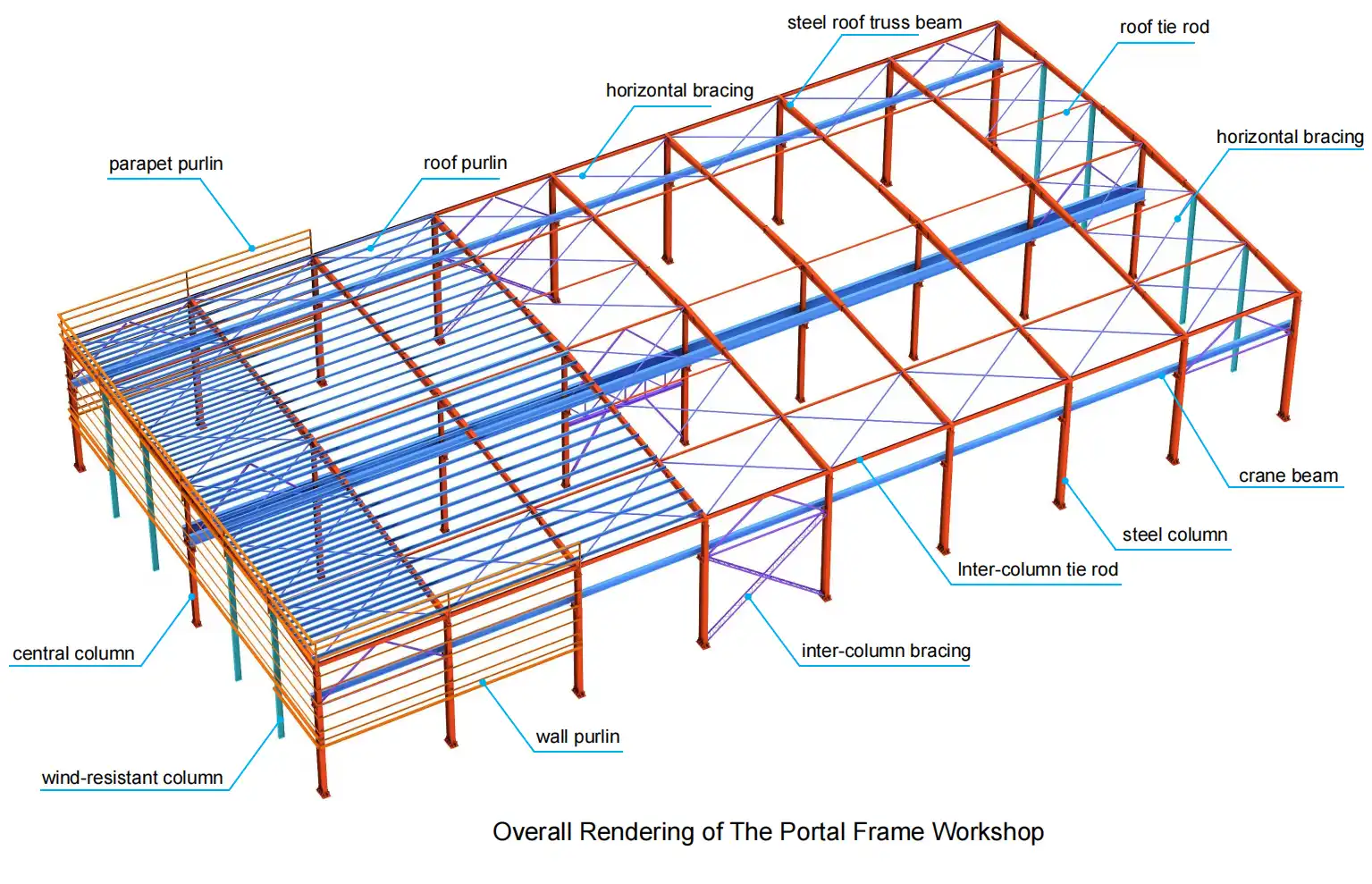
1. Mechanics: The Inherent Weak-Axis Vulnerability of Portal Frames
1.1 Structural Mechanics of the Portal Bent
A portal frame consists essentially of transverse 2D bents formed by steel columns and rafters connected through high-strength bolted moment end-plates. These bents are arranged linearly down the building axis at regular bay intervals (typically 6 m to 9 m).
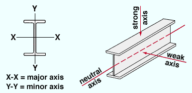
1.2 Cross-Sectional Asymmetry of I-Sections
Columns and rafters primarily use welded plate H-sections or hot-rolled I-sections. These sections exhibit starkly unequal properties across their primary axes:
-
▪
Major Axis (X-X): Bending occurs parallel to the web plate. The section modulus
Wxand second moment of areaIxare large, providing resistance against gravity dead loads, live loads, snow, and transverse wind suction. -
▪
Minor Axis (Y-Y): Bending occurs perpendicular to the web, aligned with the building's longitudinal axis. Because the flanges are relatively narrow, the minor-axis inertia
Iyis often less than 5% ofIx. Under compression and out-of-plane bending, these members are vulnerable to lateral-torsional and weak-axis flexural buckling.
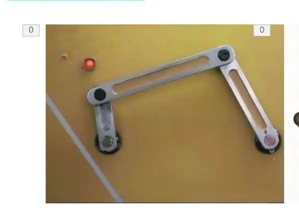
1.3 Unbraced Longitudinal Bays Form Collapsible Mechanisms
In the transverse direction, moment connections provide continuous frame action. In the longitudinal direction, however, adjacent bents are joined only by cold-formed thin-walled C or Z purlins connected through simple web cleats. These pinned connections provide zero rotational stiffness.
Without diagonal steel cross-bracing, the entire longitudinal profile of the building forms an open four-bar linkage mechanism. When longitudinal wind on gable walls or crane surge forces act on the building, the framework cannot develop restoring moments and will topple progressively along its axis.
2. The 4 Structural Functions of a Bracing System
Bracing components are primary lateral load-resisting members that convert disconnected 2D bents into an integrated 3D spatial diaphragm:
Triangulated 3D Spatial Rigidity
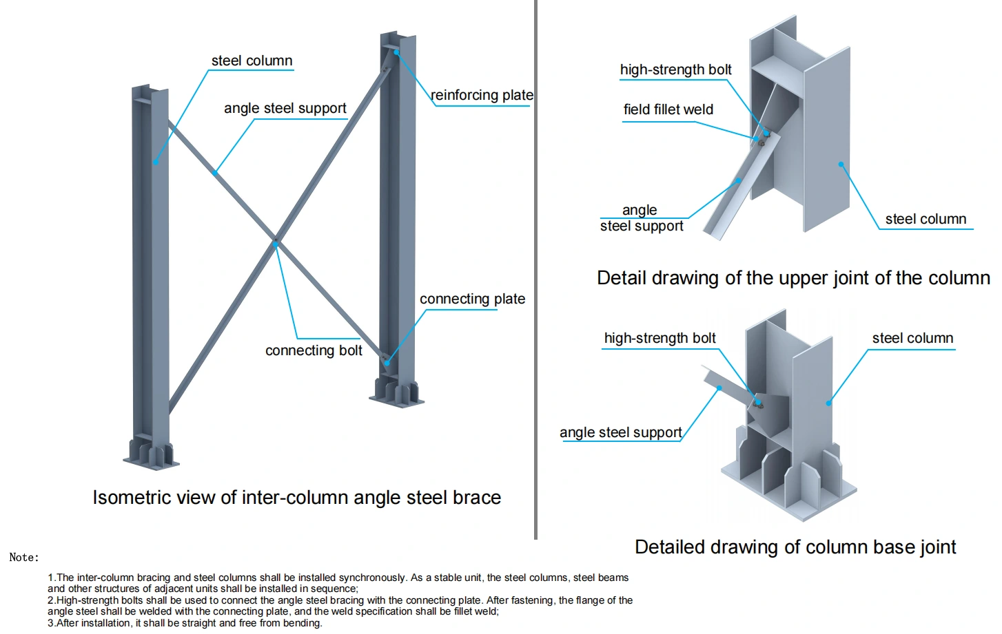
By installing diagonal braces in selected bays, quadrilateral bays are converted into rigid triangles. This locks the separate transverse bents into an integrated spatial box capable of resisting torsional and longitudinal shear.
Constraining Slenderness & Euler Buckling
Under Euler’s fundamental column equation:
Buckling resistance is inversely proportional to the square of effective length L0 = μL. Bracing and rigid struts provide discrete nodal lateral restraints, mathematically chopping the effective column buckling length down to the single bay interval.
Unbroken Horizontal Load Paths
Transverse wind on gable walls is captured by wind posts and fed into the roof horizontal bracing truss. The roof truss funnels shear along the perimeter eaves into vertical column cross-bracing, transferring loads into foundation anchor bolts. It also dissipates bridge crane braking surge and seismic ground shear.
Construction-Stage Erection Anchor
During steel erection, bare frames have no stability prior to cladding installation. Structural safety codes mandate that the first bay—comprising vertical column bracing, roof horizontal bracing, and rigid tie struts—must be plumbed, fully bolted, and locked off before releasing crane rigging to erect subsequent bents.
3. Engineering Detailing & Code Provisions (AISC 360 & GB 51022)
A complete portal frame bracing network operates as a four-part cooperative system: Column Bracing, Roof Horizontal Bracing, Rigid Tie Struts, and Fly (Flange) Braces.
| Subsystem Member | Structural Configuration | Material Specification | Code Boundary Conditions |
|---|---|---|---|
| Vertical Column Bracing | Concentric X-brace or Portal frame opening | Round rod with turnbuckle (no crane) / Structural angles & tubes (crane ≥ 5t) | Bay spacing 30m~45m (max 60m). Position in bay 1 or 2. |
| Roof Horizontal Bracing | Planar truss in rafter flange plane | Round rods with turnbuckles or structural angle shapes | Must align in same bay as column bracing. Diagonal angle 30°~60° (optimum 45°). |
| Rigid Tie Struts | Longitudinal axial compression strut | Hot-rolled structural steel tubes / pipes (Purlins prohibited) | Mandatory at ridge, eaves, and column extractions. Slenderness λ ≤ 200. |
| Fly Bracing (Flange Brace) | Triangulated angle to roof purlin | Single structural angle (L50x4 or L63x5) | Locks rafter compression flange near haunches to prevent Lateral-Torsional Buckling. |
3.4 Fly Bracing (Flange Braces): Preventing Lateral-Torsional Buckling (LTB)
Under gravity loads, hogging bending moments near rafter haunches place the bottom flange into severe axial compression. Similarly, strong wind uplift forces cause rafter bottom flanges to experience compression throughout mid-span regions.
A compression flange acts like an unbraced, slender column. Without lateral restraint, it suffers sudden Lateral-Torsional Buckling (LTB), causing the entire rafter to twist sideways and fail.
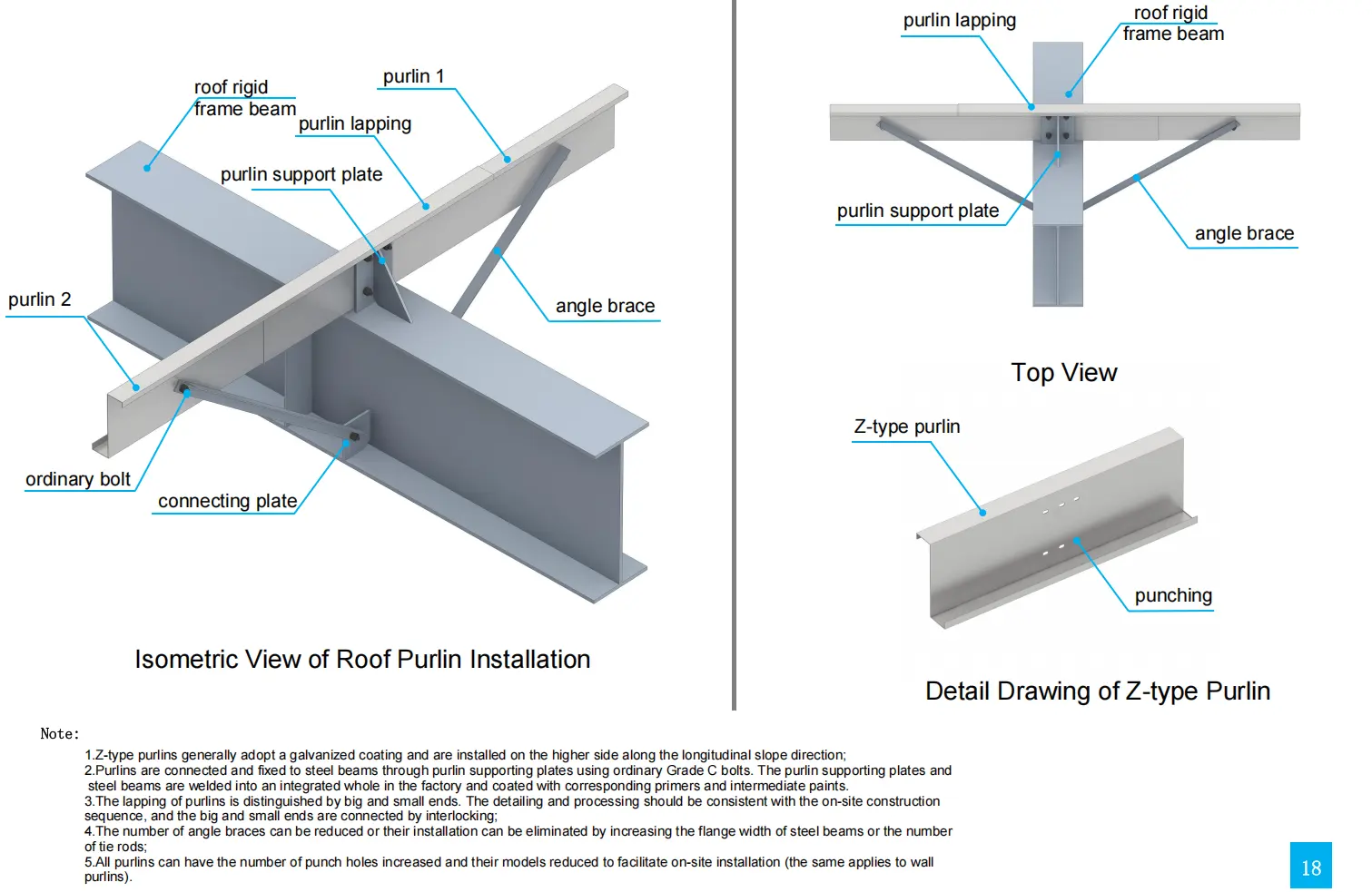
The Detailing Solution: A small diagonal steel angle (typically L50×4 or L65×5) bolted between the inner compression flange of the main rafter and the nearest cold-formed roof purlin. This diagonal strut forms a rigid triangulated brace, mechanically locking the compression flange in place and reducing the rafter’s out-of-plane unbraced length to the purlin spacing (typically 1.5 m).
4. Forensic Failure Analysis: The Simen Town Building Collapse
4.1 Official Disaster Incident Summary
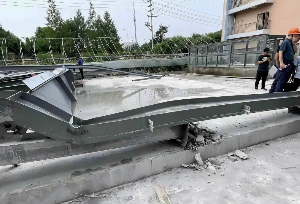
During construction in an industrial zone in Simen Town, Yuyao City, Zhejiang Province, an in-progress industrial steel structure warehouse suffered a sudden, complete out-of-plane progressive collapse. Multiple bays of portal frames collapsed longitudinally, tragically resulting in 2 fatalities and 10 severe injuries, reducing a newly framed building into twisted scrap metal.
📄 Official News Citation: Disaster investigation and casualty figures were officially documented via Guancha News Official Incident Report: Zhejiang Yuyao Steel Structure Collapse Causes 2 Fatalities.
Progression of the Collapse Chain
- 1. Native Weakness: Welded H-columns oriented with weak bending axes facing longitudinally, offering negligible unbraced out-of-plane stiffness.
- 2. Structural Void: Diagonal cross-bracing omitted on site by the contractor to expedite machinery passage.
- 3. Mechanism Activation: A moderate gust of wind struck the unclad gable wall, creating lateral displacement at the unbraced first column cap.
- 4. P-Delta Domino Topple: Gravity dead weight acting on the leaning columns generated massive second-order bending moments ($P \cdot \Delta$), shearing connection bolts and collapsing fifteen consecutive bays in seconds.
Forensic Mechanics: Why Industrial PEB Warehouses Collapse
In this video breakdown, Structural Engineer David examines structural drawing oversights that directly triggered a catastrophic warehouse collapse:
The framing blueprints show corbels on the columns, indicating an overhead bridge crane. Crane braking creates massive longitudinal impact forces. Standard codes mandate angle cross-bracing with lacing bars both above and below the corbel, combined with continuous longitudinal eave struts. Omitting both column and roof bracing left the structural framework with zero longitudinal lateral capacity.
In crane buildings, the lower column section is enlarged to carry runway beams, while the upper shaft supporting only roof loads is reduced for material efficiency. Without longitudinal bracing to provide node restraint at the column cap, the effective length of the upper shaft increases. Under gravity and crane loading, the upper shaft buckles out-of-plane once loads reach the Euler critical limit.
Without an initial braced anchor bay, construction tolerances inevitably produce minor vertical inclinations. Under heavy vertical axial loads, this minor out-of-plumb deviation triggers destructive second-order bending moments ($P \cdot \Delta$), shearing connection bolts and collapsing adjacent bents like dominoes.
5. Practical Design and Jobsite Risk Mitigation Checklist
To guarantee safe erection and service life across five decades, enforce these five site engineering rules:
Never Omit Bracing for Openings
If a loading dock or overhead door clashes with vertical cross-bracing, redesign the bay as an engineered Portal Frame Brace with heavy moment-connected columns. Never arbitrarily delete a brace on site.
Pretension Round Rod Bracing
Calibrate all turnbuckles using torque wrenches during erection. Rods must be straight and taut with adequate initial pretension. Visible gravitational sag must be eliminated.
Purlins Cannot Replace Struts
Blueprints marking struts (SC/XG) require structural hollow sections (pipes/tubes) or structural angles capable of compression capacity ($\lambda \le 200$), not light cold-formed C/Z purlins.
Sequence Erection from the Braced Bay
Always install, bolt, and align the initial braced bay with all column braces, roof horizontal trusses, and eave struts in place before casting off crane hooks to install subsequent bents.
Attach Fly Braces to the Compression Flange
Identify where rafters experience negative moments (haunches) or net wind uplift reversals, and bolt fly braces directly to the inner compression flange at a 45° angle back to the purlin. Always torque bolts completely; loose fly braces provide zero LTB resistance.
Engineer Stability into Every Bay with XinQiao Steel
A pre-engineered steel structure is not just an assembly of steel members—it is a delicately balanced three-dimensional spatial system. Backed by over two decades of global fabrication legacy, XinQiao Steel (Shandong XinQiao Steel Structure Co., Ltd.) operates a 60,000 ㎡ heavy industrial manufacturing base in Taian, China, delivering 40,000 tons of high-precision structural steel annually. With an in-house engineering force of 45+ licensed Tekla/BIM detailers and certified NDT Level-II inspection teams, we engineer and fabricate every prefab steel structure building and industrial PEB kit in strict compliance with AISC 360, AWS D1.1, and EN 1090-2 (Eurocode 3) standards.