Prefabricated Portal Frame Steel Structure Erection Sequence & Engineering Guide (PEB Installation Workflow)
In prefabricated steel structure (PEB) construction, the on-site erection sequence is a continuous management of structural load paths, not an arbitrary assembly of components. Prior to final envelope enclosure and brace tensioning, bare steel frames lack out-of-plane lateral stiffness. Deviating from proper erection protocols causes severe cumulative misalignments, forces crews to ream bolt holes under dead load, and risks progressive frame collapse under minor construction gusts.

Specialist in industrial PEB detailing, AISC 360 connection design, and overseas turnkey project delivery at Shandong XinQiao Steel Structure Co., Ltd.
PEB Assembly Progression Map: The 6-Phase Load-Path Pipeline
01. Foundation & Anchor Survey
Optical 3D coordinate audit of anchor bolt clusters, laitance chipping, and machined leveling shim-pack placement (≥70% bearing contact).
02. Initial Stable Bay Formation
Plumb 4 columns via dual theodolites, 4-point lift rafter span, and IMMEDIATELY lock cross-bracing, roof trusses & eave struts before crane release.
03. Longitudinal Extension & Runway
Advance bents bay-by-bay, tying back to the stable core with rigid tie struts. Hoist crane runway girders, calibrate rail span gauge, and torque corbel joints.
04. Gable Wind Posts & Flange Braces
Erect gable posts with vertically slotted slip connections (deflection release). Distribute cold-formed C/Z purlins and bolt fly bracing to compression flanges.
05. 100% Torquing & Non-Shrink Grout
Global 3D laser plumb check; perform 100% same-day high-strength bolt final torque. Pour high-strength non-shrink cementitious grout under all base plates (≥50 MPa).
06. Envelope Cladding & Flashing
Install roof panels upwind from eaves to ridge, seal laps with non-skinning butyl mastic, and detail engineered perimeter flashings and gutters.
1. Core Mechanics: The "Initial Stable Bay" Mandate
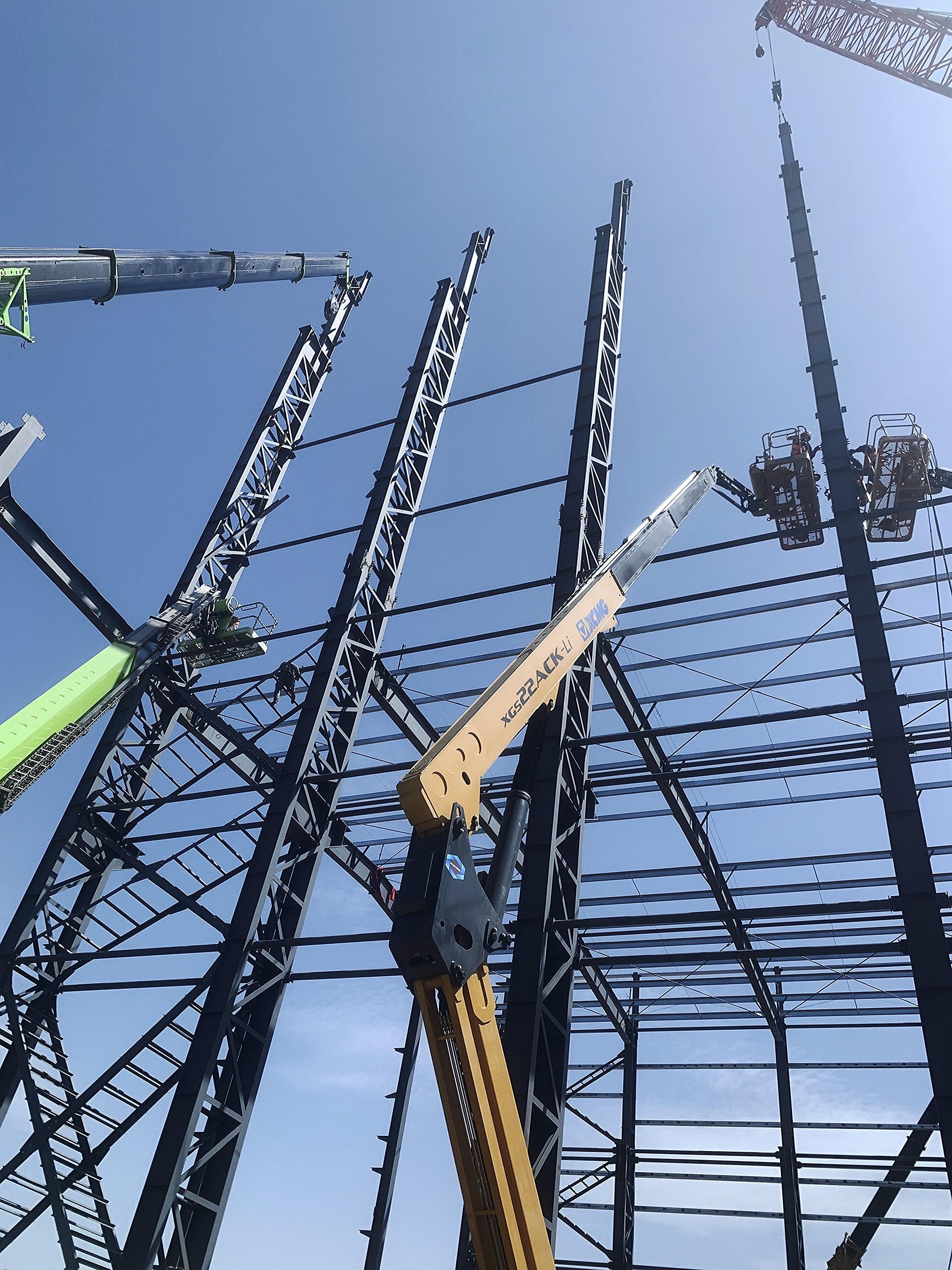
The fundamental law of pre-engineered portal frame erection is uncompromising: You must establish a fully restrained, three-dimensional geometric stable bay (Initial Braced Bay) before extending the structural skeleton longitudinally.
The Weak-Axis Reality
Welded H-columns possess vast major-axis (X-X) bending resistance against vertical gravity loads and transverse wind drift. However, their minor-axis (Y-Y) moment of inertia is typically less than 10% of their primary axis. A freestanding steel column without longitudinal tie-ins behaves as an unbraced cantilever with virtually zero overturning resistance.
Mechanism vs. Stable Structure
Transverse bents form continuous moment-resisting frames via bolted haunches. Longitudinally, however, adjacent bents connect only via cold-formed purlins with simple web cleats—providing zero rotational stiffness. Without diagonal cross-bracing, the longitudinal elevation is a collapsible four-bar linkage mechanism. Erection crews must triangulate this box with column cross-bracing and roof horizontal trusses before moving forward.
2. Pre-Erection Engineering & Jobsite Verification
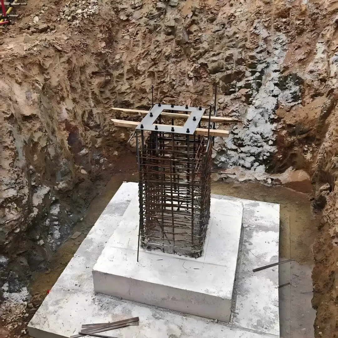
2.1 Foundation Anchor Bolt Survey & Leveling
- ▪ Three-Dimensional Survey: Using total stations and optical levels, verify anchor bolt centerlines, embedment heights, and concrete pier elevations before mobilizing cranes.
- ▪ Tolerance Strictness: Centerline deviation within any anchor bolt group must not exceed ±2 mm; column-to-column span distance must remain within ±3 mm.
- ▪ Base Plate Shimming: Clean anchor threads and install machined steel leveling shims or heavy-duty leveling nuts beneath column base plates. Ensure full bearing contact (≥ 70% flat contact area) to eliminate edge point-loading under heavy column self-weight.
2.2 Rigging & Logistics Staging
- ▪ Sequenced Staging: Unload structural components into designated laydown bays strictly matching the erection sequence. Primary columns and haunch rafters must sit within immediate crane radius to avoid secondary yard transport and coating abrasion.
- ▪ Quality Pre-Check: Inspect factory-milled splice plates, pre-punched bolt holes, and shop-applied protective coatings. Field cutting with oxy-fuel torches is strictly prohibited on certified PEB projects.
3. Step-by-Step Portal Frame Erection Sequence
Step 1: Hoisting and Plumbing the First Column Pair
Attach rigging shackles to factory lifting lugs or choked wire ropes at approximately one-third of the column height from the top. Always use curved synthetic softeners or rubber corner protectors to prevent gouging protective paint systems.
Trial Lift: Hoist the column 500 mm above the slab; inspect the crane brake system, rigging lines, and boom deflection before swinging.
Dual-Theodolite Alignment: Guide the column base plate over the foundation anchors and spin heavy hex nuts down to snug tight. Set up two theodolites at 90° angles along orthogonal gridlines. Adjust shim packs until column out-of-plumbness is within H/1000 and does not exceed 10 mm. Anchor symmetrical steel guy wires to lock the column against sudden wind gusts.
Step 2: Erecting the Parallel Column Bent
Repeat Step 1 to install the adjacent column pair across the same bay, creating a four-column footprint enclosing the primary braced bay.
Step 3: Ground Pre-Assembly and Rafter Hoisting
Ground Splicing: Pre-assemble segmented rafter sections on level timber cribbing or steel jig fixtures on the concrete slab. Verify span length and engineered camber (L/500 ~ L/1000) before torquing intermediate splice bolts.
Multi-Point Balanced Lift: Use a spreader beam and four lifting slings positioned at calculated nodal points to prevent out-of-plane lateral buckling during the transition from horizontal to inclined planes. Attach two long tag lines to rafter ends for ground crew rotation control.
Haunch Joint Connection: Maneuver the rafter cluster into the column tops. Riggers on elevated work platforms align connection endplates, insert high-strength bolts, and bring them to snug-tight condition.
Step 4: Immediate Locking of the Stable Bay (Critical Checkpoint)
Do Not Release the Crane Hook: The primary hoisting crane must maintain line tension on the rafter assembly until longitudinal stability is mechanically locked.
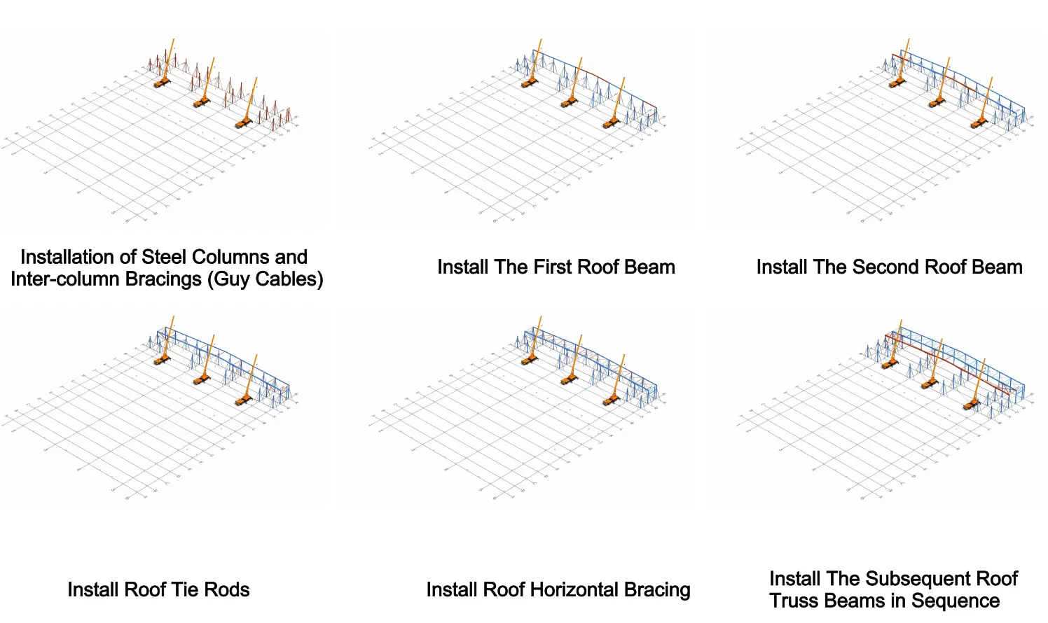
Install Bracing Subsystems: Immediately hoist and pin the vertical column cross-bracing, roof horizontal wind trusses, and rigid longitudinal eave struts. Once all diagonal turnbuckles or structural brace angles are drawn taut and connected, the bay transforms into an autonomous three-dimensional rigid structure. Only now may the crane hook be released and temporary guy wires disconnected.
Step 5: Bay-by-Bay Longitudinal Progression
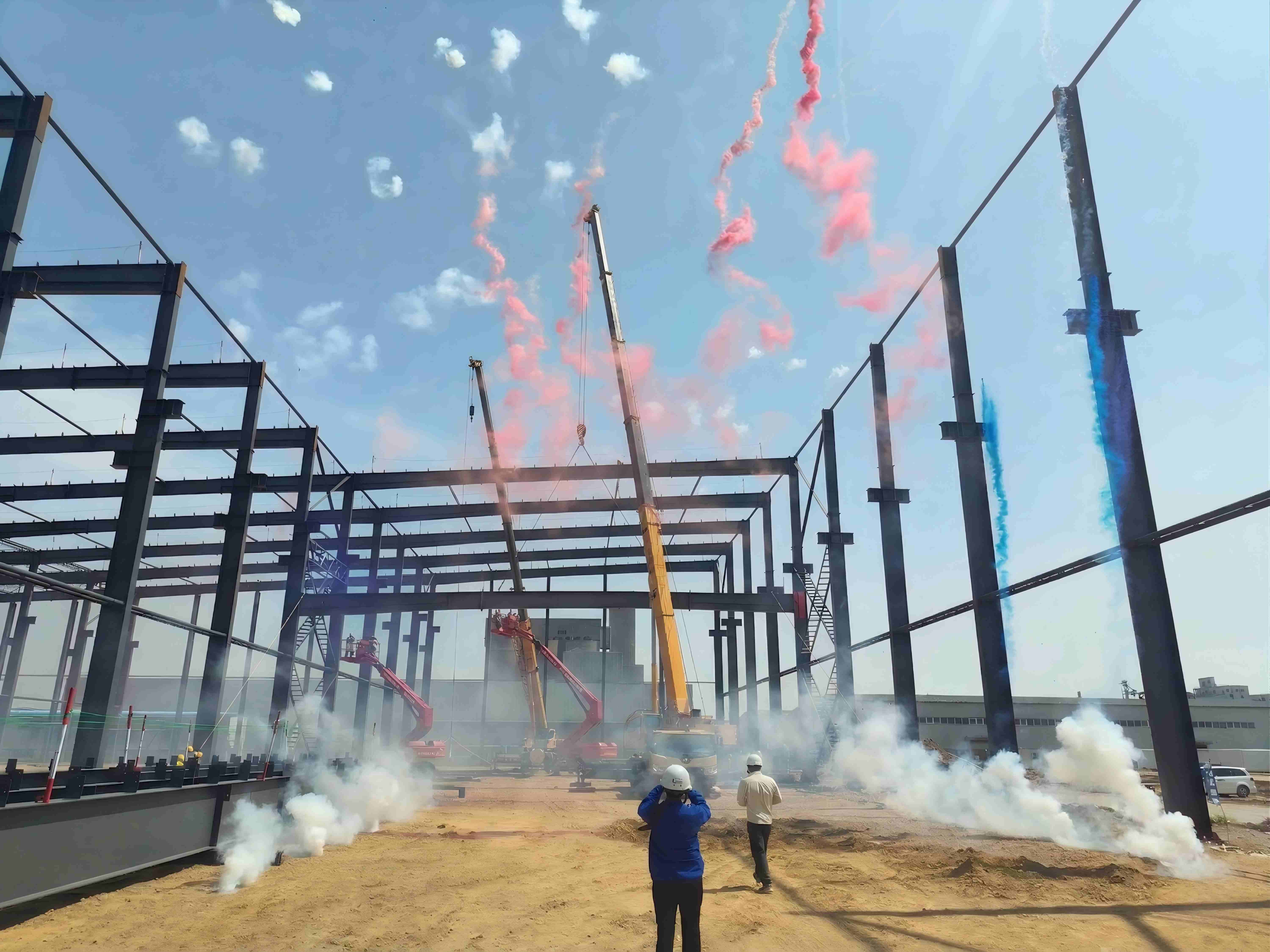
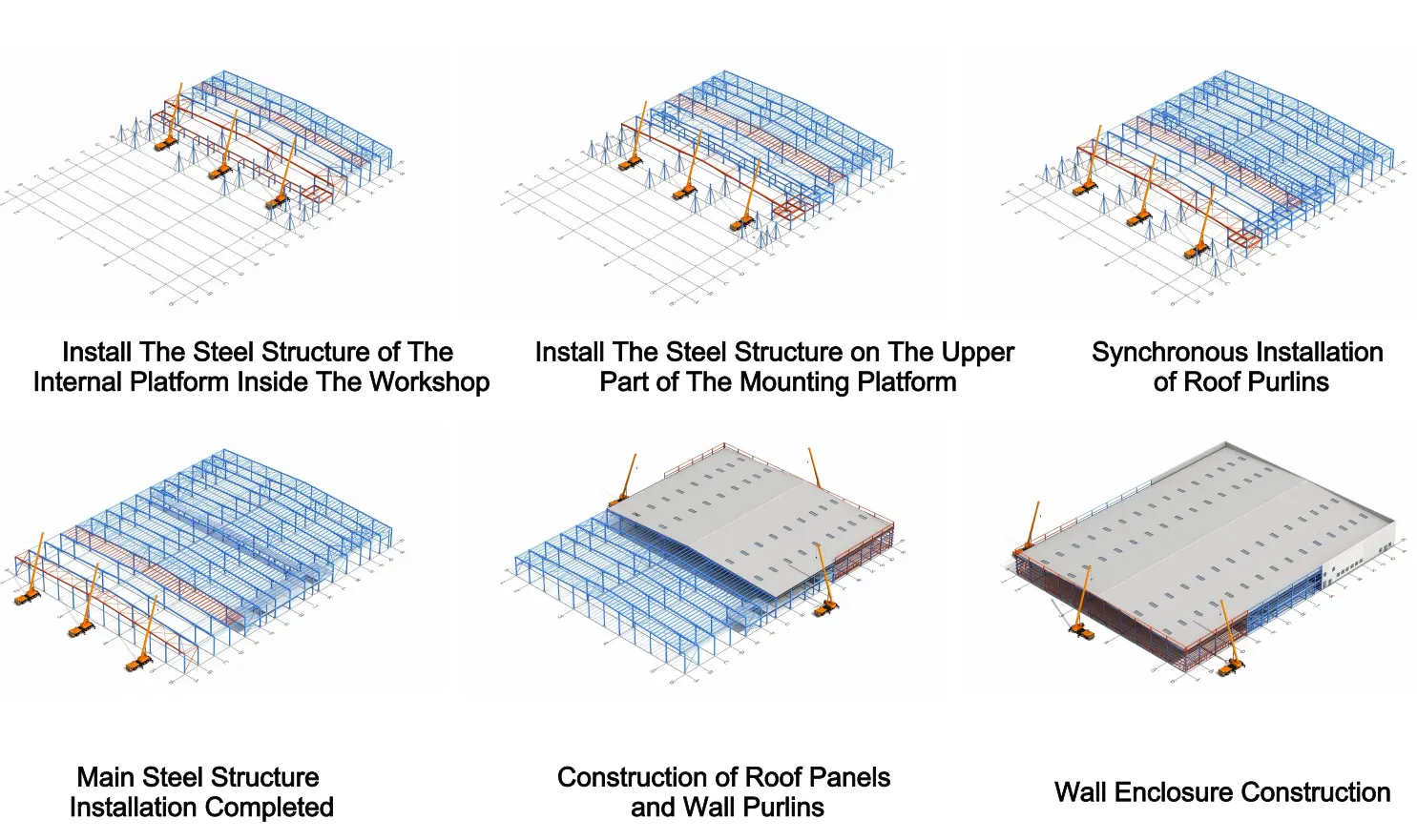
Advance the crane away from the stable bay. For each subsequent bent, erect two columns and the associated rafter span. Before slacking the hoist lines, immediately install the rigid eave tie struts and a minimum of three intermediate roof purlin lines connecting back to the preceding, stabilized bay. This maintains a continuous, self-supporting structural skeleton.
Step 6: Crane Runway Beam Installation (When Specified)
Hoist crane runway girders using balanced two-point slings, landing them squarely on column brackets (corbels).
Verify rail-top elevation (±3 mm) and centerline offset (≤ 3 mm) using laser alignment devices. Torque corbel connection bolts outward from the center of the joint to eliminate eccentric clamping stresses.
Step 7: Gable Wind Posts (Slotted Deflection Connection)
Erect vertical wind posts along the building gable end-walls to transfer lateral wind pressure into the foundation and roof horizontal diaphragm.
Vertical Slip Detailing Mandate: The top connection between the gable wind post and the underside of the main rafter must utilize vertically slotted holes or flexible leaf-spring plates. The main portal rafter must be allowed to deflect vertically under variable live, snow, and temperature loads without transferring axial compressive load down into the wind post. Welding this top connection rigid forces the wind post to act as an unintended bearing column, causing local web buckling and rafter joint cracking.
Step 8: Secondary Framing and Fly (Flange) Braces
Hoist cold-formed C/Z purlins in bundled packs directly over main rafter nodal points. Distribute them across roof planes evenly to avoid localized asymmetric loading.
Flange Brace Installation: In negative moment zones (near column-rafter haunches) and mid-span uplift reversal zones, the rafter bottom flange is subjected to severe axial compression. Bolt diagonal angle fly braces (typically L50×4 or L65×5) from the bottom flange directly to adjacent roof purlins. This cuts the unbraced length of the compression flange down to the purlin spacing, eliminating Lateral-Torsional Buckling (LTB) risks.
Step 9: Global Laser Survey & Plumb Realignment
With primary framing, secondary purlins, and all bracing components fully connected, perform a comprehensive survey of total building plumbness, eave height variations, ridge straightness, and crane runway spans before final torque.
Step 10: 100% Same-Day Bolt Torquing
Tighten all high-strength bolted connections (ASTM A325 / A490 or ISO Grade 8.8 / 10.9) using a two-stage process: Snug-Tightening followed by Final Torquing (via calibrated torque wrench or turn-of-nut method). Work outward symmetrically from the most rigid center of each joint toward free edges.
24-Hour Rule: High-strength friction bolts must achieve final torque within 24 hours of installation. Leaving bolts overnight in humid or rainy site conditions causes surface oxidation and degrades the slip coefficient of blasted steel friction surfaces.
Step 11: Base Plate Non-Shrink Grouting
Once the superstructure survey passes inspection, clean concrete pedestal surfaces, construct perimeter forms, and pour high-strength, non-shrink cementitious grout under base plates. Pour continuously from one side to eliminate air pockets, ensuring 100% bearing contact.
Step 12: Cladding & Moisture Detailing
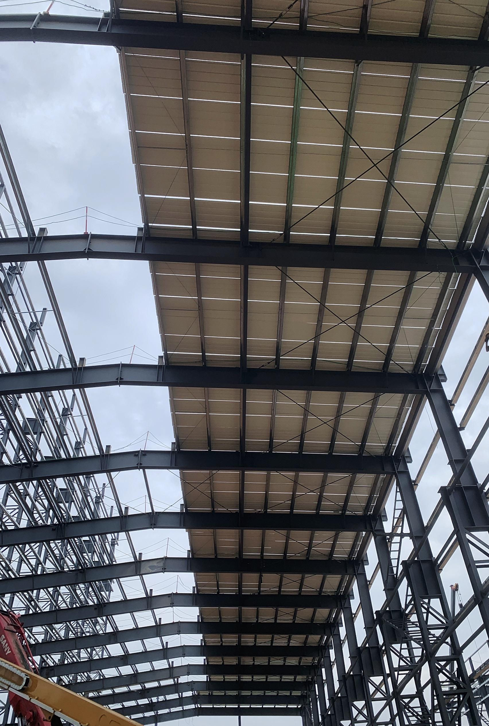
Lay profiled steel sheets or insulated sandwich panels starting from the leeward eaves and working up toward the ridge, opposing prevailing winds. Install corrosion-resistant self-drilling screws with EPDM washers. Run continuous non-skinning butyl mastic tape along all side and end laps to guarantee weathertight building envelope performance.
4. Permissible Construction Tolerances & Quality Matrix
Erection accuracy must comply strictly with structural engineering tolerances. Enforce these field thresholds prior to sign-off:
| Inspection Point | Parameter / Metric | Permissible Tolerance | Inspection Methodology |
|---|---|---|---|
| Anchor Bolts | Centerline displacement / Projection | ≤ 2.0 mm / 0 ~ +20 mm | Total Station / Steel Rule |
| Columns | Overall vertical plumbness (H ≤ 10 m) | ≤ H/1000 and ≤ 10.0 mm | Dual Orthogonal Theodolites |
| Rafter Spans | Clear span deviation / Mid-span camber | ± 5.0 mm / L/500 ~ L/1000 | Laser Rangefinder / Optical Level |
| Initial Stable Bay | Plan diagonal difference | ≤ 5.0 mm | Calibrated Steel Tape Measure |
| Crane Runway | Rail-top elevation / Span centerline offset | ± 3.0 mm / ≤ 3.0 mm | Precision Optical Level / Laser |
| Bolt Joints | Final torque compliance | Within ± 10% of design torque | Calibrated Torque Wrench (NDT) |
| Base Grouting | Bearing contact coverage / Compressive strength | 100% full bearing / ≥ 50 MPa | Ultrasonic Testing / Compression Cubes |
5. Critical Field Pitfalls & Forensic Failure Lessons
Premature Rigging Release on Unbraced Bents
Contractors often erect a single transverse bent and disconnect the crane to begin the next bay without installing diagonal braces or guy wires. A sudden thermal shift or construction gust creates overturning moments that collapse the bent sideways, bending base plates and shearing anchor bolts.
Rigidly Welding Gable Wind Post Tops
Welding the top of gable wind posts to main rafter bottom flanges locks out vertical movement. Under design snow loads, the rafter sags downward and bears heavily on the wind post, which is not sized for vertical gravity compression. The wind post buckles outward at mid-height, tearing connection plates.
Substituting Thin-Walled Purlins for Struts
Field crews frequently mistake marked longitudinal axial struts (typically labeled SC or XG on structural blueprints) for standard roof purlins. Cold-formed C/Z purlins (1.5 mm ~ 2.5 mm wall thickness) have high slenderness ratios (λ > 250) and instantly buckle under compressive wind loads on the gable end-wall.
Flame Cutting and Hole Reaming on Site
When bolt holes fail to line up, unskilled workers blow out connection holes with oxy-acetylene torches. This destroys the steel's tempered grain structure, creates stress concentration notches, and reduces the bolt-bearing shear capacity below safety code thresholds.
Upstream Precision: How XinQiao Steel Eliminates Site Erection Headaches
The smoothest construction projects are those where the risk of field error is engineered out long before steel leaves the fabrication plant. When building in remote overseas destinations where specialized heavy equipment and certified rigging crews are expensive, prefabricated structural components must fit together seamlessly upon arrival.
Operating a 60,000 ㎡ heavy industrial steel manufacturing facility in Taian, China, XinQiao Steel (Shandong XinQiao Steel Structure Co., Ltd.) solves overseas assembly challenges at the fabrication source: