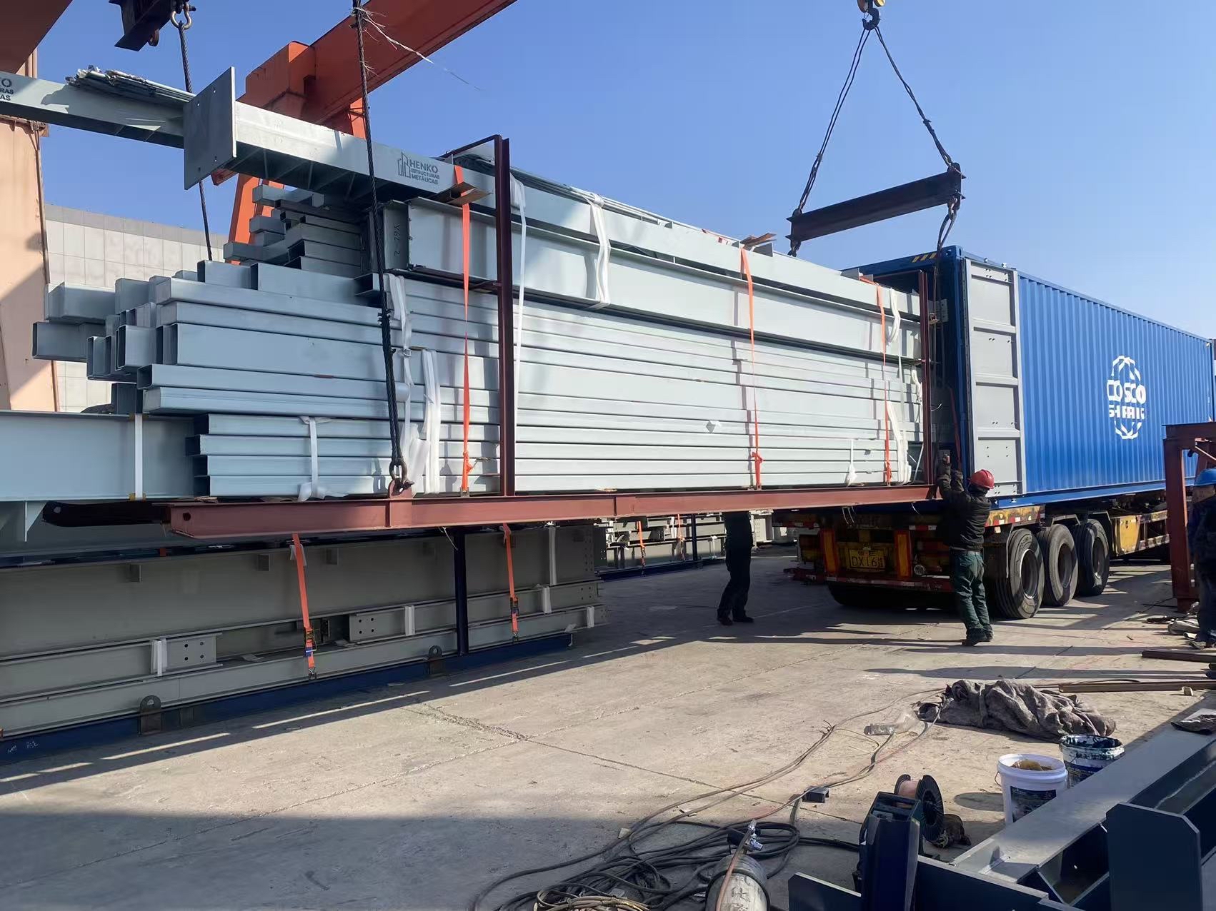
Clear-Span Prefab Steel Warehouse: Limits, Tonnage & Cost Optimization
Clear-span frames drop interior columns entirely. That means every pound of gravity and lateral load routes directly through perimeter bents into the footings, so structural limits, tonnage takeoffs, and erected costs all trace straight back to elementary statics. When span length doubles, simple-span moment doesn't just increase, it quadruples (M ≈ wL2/8).
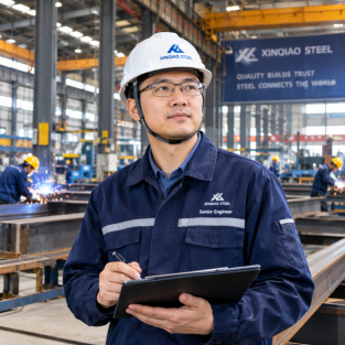
Specialist in industrial PEB detailing, AISC 360 connection design, and overseas turnkey project delivery at Shandong XinQiao Steel Structure Co., Ltd.
1. Structural Physics and Governing Mechanics of Clear-Span Portal Frames
In clear-span industrial warehouse buildings, eliminating intermediate interior columns provides unobstructed operational volume for high-bay racking systems, material handling logistics, and automated manufacturing lines. However, routing all vertical gravity forces and lateral environmental loads exclusively through perimeter moment-resisting bents imposes acute structural demands on knee haunch joints, rafter web slenderness, and foundation base connections.
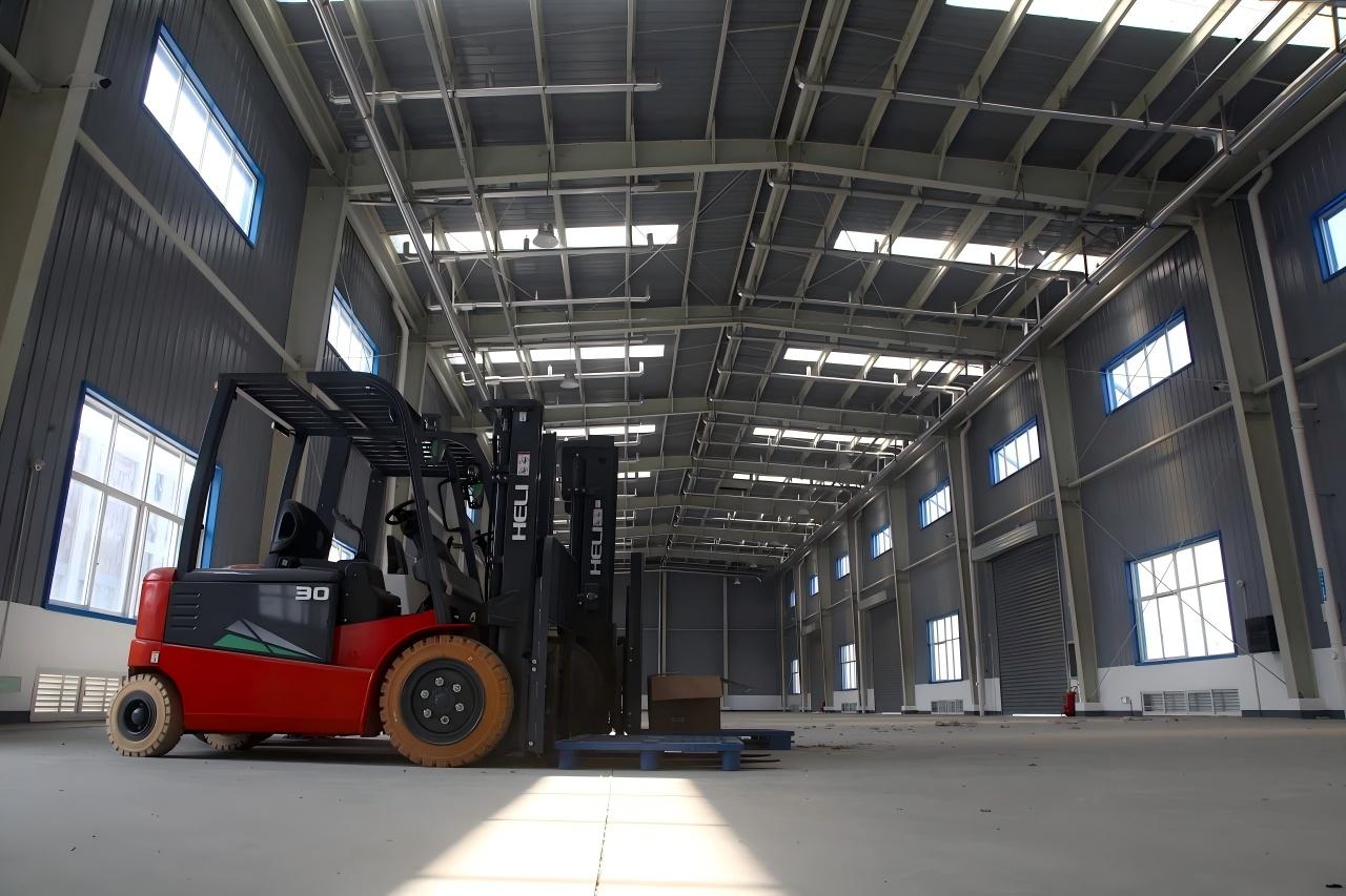
Portal frames counteract exponential mid-span deflection surges by redistributing bending stresses into rigid, moment-resisting knee haunches. This balances mid-span positive bending against negative corner moments. Without intermediate column relief, perimeter columns carry the entire roof assembly alone, resisting rafter self-weight, purlins, exterior wall cladding, suspended mechanical equipment (MEP), and drifting snow across unassisted spans.
Deep tapered haunches balance rafter sag by clamping rotation at the eave junction, transferring heavy compression into rafter bottom flanges.
Governed by quadratic moment scaling (wL2/8). Deflection is mitigated by continuous nested Z-purlins and engineered upward fabrication camber.
Outward thrust scales with haunch moment (H ≈ Mhaunch / hcol), resolving 40 to 80 kips into floor slab hairpins or tie rods.
Unbalanced loading demonstrates why clear-span portal frame design extends well beyond simple symmetric gravity checks. Under ASCE 7-22 Section 2.3 load combinations such as 1.2D + 1.6Lr + 0.5W, roof live load may act on only one rafter half while collateral dead load remains uniform across both pitches. This creates acute rotational asymmetry, concentrating high moment demand into the windward or loaded haunch. To absorb this localized stress concentration without adding dead weight across the whole bay, fabricators cut deep web tapers from high-strength ASTM A992 or Q355B structural steel plate.
Once spans stretch past 120 feet (36.5 meters), second-order P-Delta effects dictate column sizing. AISC 360-16 Chapter C mandates rigorous verification of local member curvature (P-δ) and global frame sidesway (P-Δ) via the Direct Analysis Method (DAM). At wide spans, unbraced lateral drift can exceed standard serviceability thresholds like H/60 or H/100, driving up second-order amplification factors (B1 and B2) and requiring heavier plate geometries to satisfy AISC 360-16 Table B4.1b slenderness limits.
| Clear Span Width (m / ft) | Haunch Cut Depth (mm) | Primary Frame Steel Tonnage (kg/m²) | Gravity Deflection Limit (AISC DG3) | Second-Order B2 Factor | Primary Governing Limit State |
|---|---|---|---|---|---|
| 24 m (78.7 ft) | 650 – 750 mm | 22 – 28 kg/m² | L/240 (≈ 100 mm) | 1.05 – 1.08 | Flange local buckling (bf / 2tf) |
| 30 m (98.4 ft) | 850 – 950 mm | 29 – 36 kg/m² | L/240 (≈ 125 mm) | 1.08 – 1.12 | Rafter lateral-torsional buckling (LTB) |
| 36 m (118.1 ft) | 1050 – 1200 mm | 38 – 46 kg/m² | L/240 (≈ 150 mm) | 1.14 – 1.18 | Elastic lateral wind drift (H/100) |
| 48 m (157.5 ft) | 1350 – 1550 mm | 52 – 68 kg/m² | L/240 (≈ 200 mm) | 1.25 – 1.35 | Second-order P-Δ column axial-flexural stress |
Fabrication tolerances play an essential role in structural stability. Multi-torch CNC plasma tables profile rafter and column plates within ±0.5 mm margins to provide the root fit required for AWS D1.1 complete joint penetration (CJP) welds at knee joints. All steel members undergo ISO 8501-1 Sa 2.5 centrifugal blast cleaning followed by an 80 μm dry film thickness (DFT) epoxy zinc-rich primer. On site, anchor bolts must land within ±3 mm of survey lines to avoid inducing parasitic bending moments into nominally pinned base plates.
2. AISC 360-22 Limit States: Web Slenderness, Haunch Moments, and Stability Bracing
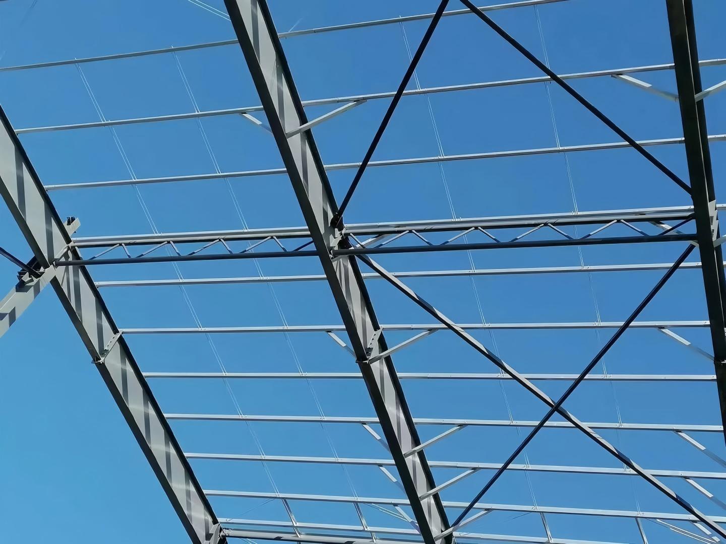
Tapered built-up plate girders optimize weight by aligning beam depth directly with internal bending moment diagrams. Unlike hot-rolled wide-flange shapes that carry unworked steel through low-stress spans, fabricated frames eliminate excess material. However, these slender web proportions place the member in stability-critical territory, making rigorous stiffening and bracing detailing essential.
2.1 Knee Haunch Mechanics and Peak Negative Moments
Negative bending peaks sharply at the eave junction where the rafter frames into the column flange. As spans exceed 120 feet, required section modulus climbs rapidly, forcing haunch depths out past 48 to 60 inches (1200 to 1500 mm) to keep flange thicknesses within manageable mill dimensions.
2.2 Web Slenderness, Shear Buckling & Flange Compactness (AISC 360-22 Chapter G & Table B4.1b)
Slender web plates keep overall dead weight down, but shear buckling requires active mitigation. In pre-engineered portal frames, web slenderness (h/tw) routinely reaches 150 to 200, exceeding the AISC non-slender boundary (2.24 √(E/Fy) ≈ 54 for ASTM A572 Grade 50 or Q355B steel).
Where Aw is web cross-sectional area, and Cv2 is the post-buckling reduction coefficient determined by web slenderness and stiffener aspect ratio.
Transverse stiffeners at spacing a/h ≤ 3.0 boost the shear buckling coefficient to kv = 5.34 + 4.0 / (a/h)2 without requiring a thicker web plate across the bent.
Flange Compactness: To prevent premature flange local buckling before reaching plastic yield, AISC caps the width-to-thickness ratio at bf / (2tf) ≤ 0.38 √(E/Fy). For ASTM A572 Grade 50 (E = 29,000 ksi, Fy = 50 ksi) and Q355B (E = 206,000 MPa, Fy = 355 MPa), the limiting ratio is:
Exceeding 9.15 drops the section into non-compact classification under AISC 360-22 Table B4.1b, requiring flexural reductions. Standardizing flange widths around mill flat-bar dimensions maintains compact classification while ensuring welding torch clearance for automated twin-wire gantries.
2.3 Wind Uplift Reversal and Bottom Flange Stability (AISC Appendix 6)
Under downward gravity loads, rafter top flanges remain in compression and benefit from continuous lateral restraint from roof purlins. However, strong net wind uplift under ASCE 7-22 load combinations (0.6D + 0.6W or 0.9D + 1.0W) flips stress distribution, placing the unbraced bottom flange into acute axial compression.
Without physical bottom-flange stabilization, the unbraced length Lb spans the entire frame bay, triggering catastrophic lateral-torsional buckling (LTB) well below the material yield point. Fabricators install diagonal angle kickers (typically ASTM A36 or Q235B, minimum L50×50×4 mm or L2×2×1/8 in) connecting the bottom compression flange directly to adjacent cold-formed purlin webs.
Connecting diagonal kickers at every second or third purlin line reduces Lb to 1.5 – 3.0 meters (4.5 – 9.0 ft), ensuring rafters develop full design flexural capacity.
| Clear Span (m / ft) | Haunch Depth dw | Web Thickness tw | Slenderness h/tw | Flange Size bf × tf | Kicker Spacing Lb | Primary Framing Tonnage |
|---|---|---|---|---|---|---|
| 24 m (80 ft) | 750 mm (29.5 in) | 6.0 mm | 125 | 200 × 10 mm | 3.0 m | 18 – 23 kg/m² (3.7 – 4.7 psf) |
| 36 m (120 ft) | 1200 mm (47.2 in) | 8.0 mm | 150 | 250 × 14 mm | 2.5 m | 25 – 32 kg/m² (5.1 – 6.5 psf) |
| 48 m (160 ft) | 1500 mm (59.1 in) | 9.0 mm | 166 | 300 × 18 mm | 1.5 m | 34 – 42 kg/m² (7.0 – 8.6 psf) |
| 60 m (200 ft) | 1800 mm (70.8 in) | 10.0 mm | 180 | 350 × 22 mm | 1.5 m | 44 – 55 kg/m² (9.0 – 11.2 psf) |
3. Clear-Span Tonnage Scaling Curves: Empirical Steel Weight from 60 to 250+ Feet
Steel consumption does not scale linearly with span width. While bending moments increase quadratically (Mu = wL2/8), elastic deflections increase to the fourth power (Δ = 5wL4 / 384EI). On long clear spans, dead load becomes the dominant structural burden. The girder carries substantial self-weight across the opening before supporting any applied roof loads, driving up web depths and thickening flanges.
Structural Weight vs. Span Length (lbs/ft² & kg/m²)
| Clear Span Width (ft / m) | Structural Typology | Steel Rate (lbs/ft²) | Steel Rate (kg/m²) | Governing AISC / EN Limit | Flange Thickness | Relative Cost Index |
|---|---|---|---|---|---|---|
| 60 – 80 ft (18.3 – 24.4 m) | Tapered Solid-Web Portal | 4.0 – 5.5 | 19.5 – 26.8 | Flexural Yielding (Mu ≤ φMn) | 10 – 14 mm | 1.00 (Baseline) |
| 100 – 120 ft (30.5 – 36.6 m) | Tapered Solid-Web Portal | 6.0 – 8.0 | 29.3 – 39.1 | Combined Bending & Flange Buckling | 14 – 18 mm | 1.28 – 1.45 |
| 150 ft (45.7 m) | Deep-Haunch Solid-Web | 9.5 – 13.0 | 46.4 – 63.5 | Web Crippling & Deflection (L/180) | 20 – 32 mm | 1.85 – 2.15 |
| 180 – 200 ft (54.9 – 61.0 m) | Transition: Plate Girder to Truss | 12.5 – 16.5 | 61.0 – 80.5 | Lateral Drift (H/100) & Shipping Limits | 32 – 40 mm (Solid) | 2.30 – 2.70 |
| 200 – 250+ ft (61.0 – 76.2+ m) | Modular Pratt / Warren Truss | 14.0 – 22.0+ | 68.3 – 107.4+ | Chord Axial Tension / Buckling | Hollow Sections (HSS) | 2.80 – 3.60 |
The 180 to 200-Foot Structural Transition: Solid-Web vs. Open-Web
Between 180 and 200 feet, solid-web plate girders hit severe economic and logistical constraints. Fabricating a 200-foot clear span as a solid plate girder requires web depths exceeding 2,400 mm (94.5 inches) simply to control live-load deflection, creating major bottlenecks:
- Highway Clearance Restrictions: Standard low-boy trailers operate with 18 to 24 inches of ground clearance, leaving only an 11.5 to 12.0-foot legal vertical clearance window before oversize permits, route surveys, and police escorts become mandatory.
- Fabrication Stiffener Labor: Slender, ultra-deep webs require transverse and longitudinal stiffeners at closely spaced intervals under AISC Chapter G, substantially increasing welding man-hours per ton.
- Surface Prep & Coating Areas: Deep continuous web plates double the total painting area. Surface preparation to ISO 8501-1 Sa 2.5 and applying 80 μm DFT primer across wide continuous plate faces drives up coating costs.
4. Foundation Boundary Conditions: Pinned vs. Fixed Base Economics and Thrust Resolution
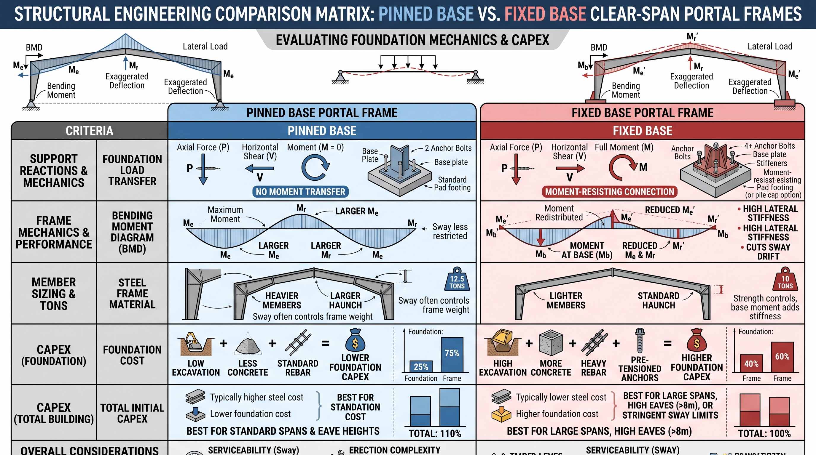
Base boundary conditions create an ongoing trade-off between superstructure steel tonnage and foundation substructure costs. Nominally pinned column bases eliminate major overturning moments from the footings, transmitting only vertical gravity reactions and direct shear. However, lateral outward thrust (H ≈ Mhaunch / hcol) routinely generates 40 to 80 kips (178 to 356 kN) of horizontal reaction per perimeter column on 30 m to 48 m spans under combined gravity and snow loads (ASCE 7-16 and IBC 2021 load combinations).
1. Hairpin Rebar Tie-Backs
Symmetrically bent reinforcing bars (#5 or #6 ASTM A615 Grade 60) hook around anchor bolts at 45°, extending into the 150–200 mm floor slab to transfer tension via bond development lengths (ld per ACI 318-19 Chapter 25).
2. Sub-Slab Tie Rods
Continuous high-strength threaded rods or rebar inside PVC sleeves beneath the floor slab connect opposing column footings, completely neutralizing outward lateral kick within the footprint.
3. Continuous Grade Beams
Heavy reinforced concrete perimeter tie beams bridge column pedestals, channeling shear into adjacent braced bays or distributed soil friction piers.
| Clear Span (m) | Base Boundary Condition | Frame Tonnage (kg/m²) | Footing Dimension (L×W×D, m) | Concrete Vol / Bent | Substructure Cost Index | Base Shear / Moment |
|---|---|---|---|---|---|---|
| 30 m (98 ft) | Pinned + Hairpins | 28.5 | 1.8 × 1.8 × 0.6 | 3.9 m³ | 1.00 (Baseline) | V = 42 kips, M = 0 |
| 30 m (98 ft) | Fixed Moment Base | 23.2 | 3.2 × 3.2 × 1.1 | 22.5 m³ | 2.45 | V = 22 kips, M = 385 kN·m |
| 36 m (118 ft) | Pinned + Tie Rods | 34.0 | 2.1 × 2.1 × 0.7 | 6.2 m³ | 1.18 | V = 58 kips, M = 0 |
| 36 m (118 ft) | Fixed Moment Base | 27.5 | 4.0 × 4.0 × 1.3 | 41.6 m³ | 3.60 | V = 31 kips, M = 640 kN·m |
| 48 m (157 ft) | Pinned + Tie Rods | 46.5 | 2.6 × 2.6 × 0.8 | 10.8 m³ | 1.42 | V = 78 kips, M = 0 |
| 48 m (157 ft) | Fixed Moment Base | 38.0 | 5.2 × 5.2 × 1.5 | 81.1 m³ | 5.15 | V = 44 kips, M = 1,120 kN·m |
While fixed bases reduce frame rafter moments by 20% to 30% (saving 4 to 8 kg/m² in steel), that mass shifts directly into the civil foundation package. Where allowable soil bearing capacity is low (qallow < 2,500 psf or 120 kPa), footing dimensions must expand to keep load eccentricity within the middle third (e = M/P ≤ B/6), causing foundation concrete volumes to quadruple.
5. Secondary Framing Optimization: Bay Spacing, Nested Z-Purlins, and Diaphragm Action
Secondary structural framing accounts for 30% to 42% of total structural tonnage in a pre-engineered warehouse. Optimizing bay spacing produces immediate capital expenditure savings because cold-formed galvanized profiles carry lower fabrication labor costs per kilogram than built-up welded plate bents.
| Longitudinal Bay Spacing | Frames (300 ft Building) | Secondary Purlin Profile (ASTM A653) | Lap Length over Rafter | Foundation Count | Secondary Weight | Net Cost Advantage |
|---|---|---|---|---|---|---|
| 20 ft (6.10 m) | 16 Frame Lines | Z8 × 2.5 × 16 ga (203 mm, 1.5 mm t) | 36 in (914 mm) | 32 Footings | 5.8 – 6.5 kg/m² | Baseline (0%) |
| 25 ft (7.62 m) | 13 Frame Lines | Z9.5 × 3.0 × 14 ga (241 mm, 1.9 mm t) | 48 in (1219 mm) | 26 Footings | 7.2 – 8.1 kg/m² | 18.75% Frame Reduction |
| 30 ft (9.14 m) | 11 Frame Lines | Z11.5 × 3.5 × 12 ga (292 mm, 2.6 mm t) | 60 in (1524 mm) | 22 Footings | 9.1 – 10.4 kg/m² | 31.25% Frame Reduction |
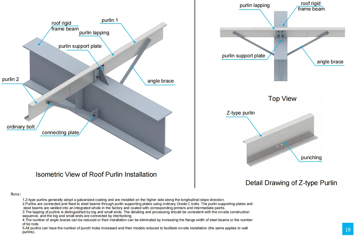
Nested Continuity per AISI S100-24: Simple single-span purlins must resist large positive mid-span bending moments (Mu = wL2/8). In contrast, continuous Z-sections with asymmetrical flanges (3.25-inch top, 3.00-inch bottom) nest over rafter supports. Lapping purlins 10% to 15% past the rafter flange creates a double-thickness section over support zones where negative moments peak (Mu ≈ wL2/12), shifting inflection points and maintaining live-load deflections between L/180 and L/240.
6. Envelope Serviceability: Deflection Limits, Lateral Drift, and Tilt-Up Cladding Integration
Once spans exceed 30 meters, serviceability limits often govern member sizing before flexural stresses reach plastic capacity (Mp). Wind drift and live-load deflection dictate column depths and flange dimensions. ASCE 7-22 Chapters 26 through 31 and Appendix CC govern these limits based on envelope ductility.
| Cladding Interface System | Wind Event Reference | Max Lateral Drift Limit | Vertical Deflection (Live/Total) | Primary Steel Weight Penalty | Design Code |
|---|---|---|---|---|---|
| Standard Corrugated Metal (0.5–0.75 mm) | 10-Year MRI Wind | H/60 to H/100 | L/180 (Live) / L/240 (Total) | Baseline (0.0 lbs/ft²) | AISC DG3, ASCE 7-22 |
| Insulated Metal Panels (IMP) & Glass | 10-Year MRI Wind | H/200 to H/250 | L/240 (Live) / L/300 (Total) | +0.6 to 1.2 lbs/ft² (2.9 to 5.9 kg/m²) | AISC 360-16, AAMA 501 |
| Reinforced CMU Masonry Walls | 25-Year MRI Wind | H/400 | L/360 (Live) / L/480 (Total) | +1.5 to 2.2 lbs/ft² (7.3 to 10.7 kg/m²) | TMS 402/602, AISC DG3 |
| Precast Tilt-Up Concrete Panels | 25-to-50-Year MRI | H/400 to H/500 | L/360 (Live) / L/480 (Total) | +1.8 to 3.0 lbs/ft² (8.8 to 14.6 kg/m²) | ACI 318-19, AISC DG3 & 13 |
Stiffening a frame for brittle tilt-up concrete requires substantial steel increases. Controlling drift from H/100 to H/400 adds 1.8 to 3.0 lbs/ft² of primary steel solely to increase column moment of inertia (Ix), replacing 6–8 mm webs with 12–16 mm plates and 25–40 mm flanges. In addition, slotted connector clips with PTFE slide bearings decouple vertical roof deflection from perimeter panels, allowing rafters to flex freely under total load without imposing unintended gravity loads on non-load-bearing walls.
7. Structural System Thresholds: Solid-Web Portal Frames vs. Open-Web Trusses and Space Frames
Selecting the correct structural framing typology establishes the baseline capital expenditure for any industrial facility. Evaluating raw steel mass alone is incomplete; engineering teams must evaluate shop welding hours, transport logistics, and crane lifting cycles together.
Lowest shop labor per ton; automated twin-wire submerged arc welding; rapid 1-pick rafter erection.
Deflection and shear transition zone; requires transverse web stiffening and bolted field splices.
High axial chord efficiency; eliminates heavy web plates; ships easily in standard containers.
Bi-axial load sharing via spherical forged nodes; ground assembly with tandem hydraulic lifts.
| Framing System | Span Range | Consumption (kg/m²) | Shop Labor (Hrs/Ton) | Max Shipping Depth | Field Splice Type | Crane Picks / Bent | Erected Cost Index |
|---|---|---|---|---|---|---|---|
| Built-Up Tapered Portal | 60–150 ft (18–45 m) | 26 – 42 | 10 – 14 | 10.5 ft (3.2 m) | ASTM A325 Preloaded Endplate | 3 Picks (2 Col, 1 Rafter) | 1.00 (Baseline) |
| Hybrid Welded Plate Girder | 150–180 ft (45–55 m) | 45 – 62 | 14 – 18 | 12.0 ft (3.65 m) | Extended Moment Endplates | 4 to 5 Picks | 1.35 |
| Modular Pratt / Warren Truss | 180–260 ft (55–80 m) | 38 – 54 | 18 – 24 | 9.8 ft (3.0 m) | Gusseted High-Strength Chords | 5 to 7 Picks (Segmented) | 1.45 |
| Bi-Axial Tubular Space Frame | 250–360+ ft (75–110+ m) | 36 – 48 | 28 – 35 | 4.0 ft (1.2 m) | Internal Bolts to Forged Nodes | Ground Assembly + Tandem Pick | 1.85 |
8. Engineering Decision Matrix and Capex Optimization Framework
Designing exclusively for lowest structural steel tonnage often produces higher total project costs. True value engineering balances steel mass, shop welding hours, concrete substructure volume, and site crane assembly cycles.
| Clear Span | Optimal Bay Spacing | Soil Bearing Capacity | Recommended Framing System | Base Type | Steel Rate | Footing Vol. | Cost Multiplier |
|---|---|---|---|---|---|---|---|
| 24 m (80 ft) | 7.5 m (25 ft) | < 2,500 psf (120 kPa) | Solid-Web Tapered Portal (A572 Gr 50) | Pinned + Hairpins | 24 – 28 kg/m² | 1.00 | 1.00 (Baseline) |
| 30 m (100 ft) | 8.5 m (28 ft) | > 4,000 psf (190 kPa) | Solid-Web Tapered Portal (A572 Gr 50) | Pinned + Pad | 29 – 34 kg/m² | 0.85 | 1.08 |
| 36 m (120 ft) | 9.0 m (30 ft) | < 2,500 psf (120 kPa) | Haunched Tapered Portal / Rigid Rafter | Fixed Moment Base | 36 – 42 kg/m² | 1.45 | 1.26 |
| 48 m (160 ft) | 9.0 m (30 ft) | > 4,000 psf (190 kPa) | Castellated Rafter or Prismatic Truss | Pinned + Tie-Rods | 44 – 52 kg/m² | 1.10 | 1.38 |
| 60 m (200 ft) | 7.5 m (25 ft) | > 4,000 psf (190 kPa) | Open-Web Modular Steel Truss (AISC 360) | Fixed + Grade Beams | 55 – 68 kg/m² | 1.65 | 1.62 |
Lever 1: Longitudinal Bay Optimization
Expanding longitudinal bay spacing from 20 ft (6.0 m) to 28 or 30 ft (8.5–9.14 m) yields larger capex savings than shaving fractions of an inch off rafter plates. Expanding bays eliminates entire portal frame assemblies along with their concrete piers, anchor bolt groups (±3 mm layout tolerance), and crane picks. While cold-formed Z-purlin depths step up from 200 mm to 250 mm (AISI S100, 1.8 to 2.2 mm thickness), eliminating primary framing lines cuts erected superstructure costs by 8% to 12%.
Lever 2: Substructure Coordination and Base Fixity
Soil bearing capacity governs base fixity economics. In soils below 2,500 psf, transferring column overturning moments into the ground forces engineers into massive spread footings or drilled shafts to satisfy ACI 318 rotation limits. Pinned bases detailed per AISC Design Guide 1 Section 2.3 eliminate moment transfer. Combining pinned base plates with bottom-flange tension ties or rebar hairpins anchored into the 150–200 mm slab resolves horizontal thrust without expanding substructure excavation.
Lever 3: Standardized Fabrication Geometry
Standardizing rafter geometry cuts CNC cutting and SAW welding setup times by roughly 15%. Dual-grade ASTM A992 or ASTM A572 Gr 50 plate (Fy = 50 ksi / 345 MPa) provides the best strength-to-cost ratio. Maintaining uniform flange widths (for example, 250 mm across both the tapered rafter body and knee haunches) allows automated beam lines to weld flanges continuously without stopping for manual torch adjustments. Standard widths keep CNC plate nesting scrap below 4% while meeting EN 1090-2 tolerances. Finally, nesting purlins 10% to 15% across rafter flanges develops negative-moment continuity, allowing lighter cold-formed gages across the roof envelope.
9. Governing Structural Codes & Design References
The design criteria, tolerances, and mechanical calculations presented in this engineering guide comply with the following international design codes and standards:
Base Plate and Anchor Rod Design (2nd Edition)
Fisher, J. M., & Kloiber, L. A. (American Institute of Steel Construction, 2006).
Building Code Requirements for Structural Concrete
Chapter 17: Anchoring to Concrete — American Concrete Institute (2019).
Standard Specification for Anchor Bolts
Steel, 36, 55, and 105-ksi Yield Strength — ASTM International (2020).
Code of Standard Practice for Steel Buildings
Section 7.5: Anchor Rods and Foundation Bolting — AISC (2022).
Eurocode 3: Design of Steel Structures
Part 1-8: Design of joints — European Committee for Standardization (CEN, 2005).
Eurocode 2: Design of Concrete Structures
Part 4: Design of fastenings for use in concrete — CEN (2018).
Execution of Steel Structures & Aluminium
Technical requirements for steel structures (EXC2 & EXC3) — CEN (2018).
Mechanical Properties of Fasteners
Carbon steel & alloy steel bolts, screws and studs — ISO (2013).
Upstream Precision: How XinQiao Steel Eliminates Site Erection Headaches
The smoothest construction projects are those where the risk of field error is engineered out long before steel leaves the fabrication plant. When building in remote overseas destinations where specialized heavy equipment and certified rigging crews are expensive, prefabricated structural components must fit together seamlessly upon arrival.
Operating a 60,000 ㎡ heavy industrial steel manufacturing facility in Taian, China, XinQiao Steel (Shandong XinQiao Steel Structure Co., Ltd.) solves overseas assembly challenges at the fabrication source: